カテゴリー
category_usa

Power Transformer

What Is a Power Transformer?

Power Transformers
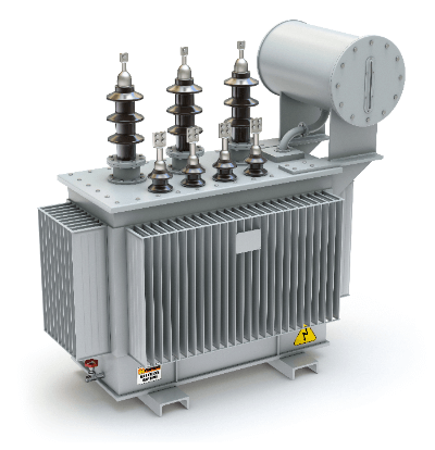
A power transformer is a transformer that transforms electrical AC voltage using electromagnetic induction.

The official name is transformer, but the word power transformer is already well established. Electrical products, for example, are powered by AC outlets, but there are many components in those products, such as motors, that are used with DC electricity instead of AC.

Also, many of those components that can be used in AC are too high voltage to be used with the 100V voltage from the outlet. For this reason, electrical products incorporate small power transformers for the purpose of varying the voltage and current, so that they always operate at the optimum voltage.

Uses of Power Transformers

The primary use of power transformers is as electrical equipment for boosting and lowering the voltage of alternating current.

Larger ones are used at substations to reduce the high AC voltage values sent from power plants and other sources, while smaller ones are used as transformers to change the voltage of electrical outlets to the proper value at shavers and other overseas destinations.

Power transformers are used in a wide range of applications, both industrial and residential, and are indispensable for converting voltage values to appropriate values.

Principle of Power Transformer 

The principle of a power transformer is based on the laws of electromagnetic induction.

It is based on the physical phenomenon that the electromotive force, due to the magnetic field fluctuation generated in a coil, is proportional to the number of turns of the power transformer. Power transformers generally consist of two coils wound around an iron core, with the primary coil on the input side and the secondary coil on the output side. The coil generates an electromotive force by changing the strength of the magnetic field within the coil; applying an AC voltage to the primary coil generates a magnetic field in the iron core, and the electromagnetic induction effect of this magnetic field induces a current in the secondary coil, generating an electromotive force.

The magnitude of the electromotive force generated in the secondary coil and the number of coil turns are in a proportional relationship, and the magnitude of the voltage can be changed by the number of turns of the secondary coil relative to the primary. In an ideal Power Transformer, the capacitance of the input and output sides should be the same, but in reality, there is a power loss due to resistance, which is mostly dissipated as heat.

Types of Power Transformers

1. Power Transformer

Power transformers are used in AC commercial power supplies to isolate the power line from the equipment power supply to ensure safety.

Power transformers with INPUT: 100V / OUTPUT: 100V are used for equipment whose power supply is 100V AC. The commercial power supply is 100V or 200V AC power, but the power supply from the power company is a much higher voltage power source up to the nearest column transformer, which is grounded by taking out 100V in the positive and reverse phases at the secondary side of the column transformer and 0V at the neutral line. If a leakage current occurs in equipment that does not use power transformers, the leakage voltage of 100 V to ground is applied to the equipment, and if a person touches the equipment, he or she will receive an electric shock. In such cases, Power Transformers can prevent electric shock by insulating both the 100V side and the neutral wire side from the 100V side and the neutral wire side of the commercial power supply. 

2. Power Transformer on a Pole

Power transformers are installed on utility poles, which are often seen in the city, in addition to holding the power lines that supply electricity. Power transformers may be installed slightly below the low-voltage lines.

The power transformer receives 6600V from the high voltage line and supplies 100V to the low voltage side. The low-voltage side (secondary side) has a positive-phase 100V and a reverse-phase 100V, so that 200V can be obtained between the positive and reverse phases (single-phase 200V / voltage to ground is 100V).

The high-voltage lines on the poles transmit power at 6600V, but even higher voltages are used on the towers that transmit power over longer distances. The reason for transmitting power at high voltage is to reduce transmission losses. Electric wires have electrical resistance, albeit slight, and voltage loss occurs in proportion to the current flowing through them. To reduce transmission loss, it is necessary to reduce the current as much as possible, and power is transmitted at a high voltage to maintain a constant transmission power.

Other Information on Power Transformers

Silicon steel or amorphous steel is used for the internal iron core of power transformer structures, but because of the higher cost of amorphous steel, a laminated iron core made of stacked silicon plates with a silicon content of about 4% and a thickness of 0.35 mm is often used.

Power transformer coils can be single or double wound. Double winding is usually used because the primary and secondary coils can be insulated, but single winding is sometimes used for reasons such as larger size and higher cost.

Power transformers need to be cooled to prevent heat generation due to voltage conversion losses. Power transformers, for this purpose, are oil-filled transformers or dry-type (molded) transformers. The former is cooled by soaking the inside of the transformer with insulating oil, while dry or molded Power Transformers that incorporate a cooling mechanism using varnish or epoxy resin are widely used in hospitals and office buildings from the standpoint of disaster prevention.

カテゴリー
category_usa

AC Cable

What Is AC Cable?

Cord SetsAn AC cable is a cable that accompanies an AC adapter that converts AC power into DC power. It transmits AC power from an outlet power supply, etc.

AC adapters are mainly used in electronic equipment such as PCs, and AC cables accompany them as well. Cable lengths vary but are limited to 30-50 m considering voltage drop.

There are several typical types of AC cables: a power cable, which supplies power to computers, displays, and other electronic products. There are two types of AC cables of this type: 2P (outlet side) – 2P (device side) type and 2P (outlet side) – 3P (device side) type.

Most AC cables for AC adapters are of the 2P (outlet side)-2P (AC adapter side) type, with the AC adapter side generally having a spectacle-shaped shape. Since the plugs in Japan have two plugs, the outlet side is mostly 2P type, but there is also a 3P type with grounding on the outlet side.

Principle of AC Cables

AC cables have a simple structure with copper wires covered with a rubber or polyethylene sheath. The copper wire transmits electric power.

The AC adapter to which the AC cable is connected converts AC power supplied from a household outlet into DC power and is classified into two types according to its internal structure: transformer type and switching type.

In general, the switching type tends to have higher conversion efficiency and generates less heat, and most AC adapters for PCs are of the switching type. However, the switching type has the disadvantage of having more components and a shorter life span than the transformer type.

Transformer-type AC adapters are designed to rectify and rectify AC power that has been stepped down by a direct transformer to direct current. Since the transformer is built in, heat is constantly generated, and the structure is simple and robust in exchange for poor conversion efficiency.

Some electrical products are made on the assumption that they are powered by either a transformer or switching type power supply, and using an AC adapter of the wrong type may result in malfunctions.

How to Select an AC Cable

First, select the length of the cable. When using a computer in a café, a tabletop is nearby, and a long AC cable is cumbersome, so select a short one. On the other hand, if you want to keep electronic devices away from power outlets, it is better to choose a long cable.

Some products can be connected to voltages up to 250V outside of Japan, and those come with adapters to convert from 2-hole to 3-hole, so it is necessary to select the product that best suits the situation in which you will be using the product.

カテゴリー
category_usa

Sealant

What Is a Sealant?

Sealants

A Sealant is a material used to fill joints and gaps to prevent water and air from entering.

Sealants are also used to fill gaps in buildings and structures to provide cushioning and prevent damage to building materials. Sealants are flexible and maintain a certain degree of elasticity even after drying, allowing them to accommodate the movement of materials. They do not hold materials firmly together like an adhesive, but their main purpose is to fill gaps.

Sealant is also a term used in the field of dentistry. It refers to a highly effective method of cavity prevention that uses a plastic resin to fill gaps between back teeth.

Uses of Sealants

Sealants are used to fill in the joints of buildings and structures to make them watertight, confidential, cushioned, or anchored. Specific applications are as follows:

1. Gaps Between Windows and Doors of Houses

Sealants can be used in the gaps between windows and doors of houses to prevent water and wind from entering, and to improve thermal and sound insulation.

2. Joints in Bathrooms and Kitchens

Sealants can be used in bathroom and kitchen joints to prevent water and dirt from penetrating and to inhibit the formation of mold and blackening.

3. Cracks in Outdoor Roofs and Walls

Sealants can be used on cracks in outdoor roofs and walls to prevent rainwater intrusion and building deterioration.

4. Gaps in Automobile Windows and Sunroofs

Sealants can be used to seal gaps in automobile windows and sunroofs to prevent water and wind from entering and to maintain a comfortable interior environment.

Principles of Sealants

Sealants work primarily on the following principles:

1. Fill Gaps

Sealants fill gaps to prevent water and air from penetrating. The flexibility of the sealant also allows the material to move and fill the gap.

Since the sealant is in liquid form before curing, it can be sealed even if the bonding surface is uneven. It also absorbs tolerance variations such as joints.

2. Adhesion

Sealant has the ability to adhere to materials. This prevents the sealant from floating out of the gap. Furthermore, since it also has adhesive strength, it can be expected to prevent bolts from loosening.

3. Weather Resistance

Sealant is resistant to ultraviolet rays and temperature changes. This makes the sealant resistant to deterioration and allows it to continue working to fill gaps over a long period of time.

Types of Sealants

There are many different types of sealants. Each sealant is used for different purposes, depending on the characteristics of the sealant. The following is an overview of typical sealants:

1. Silicone Sealants

Silicone sealants are mainly composed of silicone resin, which has high water and weather resistance and is suitable for many materials. In particular, they are often used for joints in bathrooms and kitchens, and for cracks in roofs and walls. Silicone sealants are also highly elastic and can handle the opening of gaps caused by material movement.

2. Acrylic Sealants

Acrylic sealants are made primarily of acrylic resin and are less expensive than silicone sealants. They are considered safe to use since they are water-based. They have a disadvantage of significant volume shrinkage as the water evaporates and the sealant hardens after application. It is often used for gaps between windows and doors of houses and for cracks in interior walls.

3. Urethane Sealants

Urethane sealants are mainly composed of urethane resin and have strong adhesive strength and elasticity. They also have excellent abrasion resistance and oil resistance. As a result, they are often used for gaps between parts of automobiles and ships. However, their low resistance to ultraviolet rays requires caution when used outdoors.

Other Information on Sealants

1. Precautions for Using Sealants

If sealants are not applied in the proper amount, product failure or other hazards can occur due to the following reasons:

  • If Too Much Is Applied
    Sealant may penetrate into the interior of the product and become a foreign substance.
  • If Too Little Is Applied
    The sealant may be insufficient to maintain confidentiality.

2. Application Method

Sealant can be applied to both sides of the sealant surface or only to one side. The following are points to be considered:

  • When Applying to Both Sides
    In order to apply the sealant before it cures, it is necessary to apply the appropriate amount of sealant.
  • When Applying to One Side
    The surface to which sealant is not applied should be even, as it must be cured before assembly.
カテゴリー
category_usa

Linear Servo Motors

What Is a Linear Servo Motor?

Servo Linear Motors
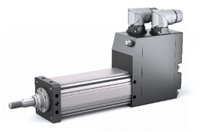
A linear servo motor is an electric motor that does not have a built-in rotating shaft and is capable of linear motion for use in servo mechanisms utilized in machine control.

While general motors perform rotary type motion, linear motors generally perform linear type motion. Linear motors themselves are devices for driving and propulsion widely known as linear motor cars, etc. Servomotors are motors used to control position, speed, etc. in servo mechanisms.

Until recently, rotary servo motors have been the mainstay of linear motion systems for industrial machinery and measuring instruments, but in recent years, linear servo motors, which operate by the action of the magnetic flux generated by a permanent magnet and the current flowing through a coil (Fleming’s left-hand rule), have been attracting attention.

Uses of Linear Servo Motors

Linear servo motors are used in a variety of applications. In particular, applications vary depending on the size.

1. Small Diameter (φ4 to 12 mm)

These are used in desktop-type equipment. Mainly used for observation of industrial products and biotechnology-related products. Shaft motors are required to have high resolution in fields where higher resolution images and image processing are required.

2. Medium Length (Up to Φ35mm)

This size is the most widely used in fields that require high thrust, high precision, and high speed, and is widely used for various positioning and moving parts in machine tools and semiconductor equipment.

3. Large Diameter (Up to Φ60mm)

Other applications include special machines that require large acceleration thrust.

Principle of Linear Servo Motors

The linear motion of a linear servo motor is based on the principle that a linear motor, which consists of a shaft with a magnet on its axis and a mover containing a coil, generates thrust through the action of the current flowing through the coil and the magnetic flux generated by the permanent magnet, or Fleming’s left-hand rule.

The shaft is usually a pipe made of stainless steel filled with magnets at equal intervals, and the mover consists of a three-phase coil wound around the shaft. The mover does not come into contact with the shaft, and its incorporation does not affect the thrust itself, making it easy to install. It operates by generating thrust through the action of the magnetic induction flux generated by the permanent magnet and the current flowing in the coil.

Features of shaft-based motors include high-precision positioning when high-precision linear scales are used, no backlash, and almost no cogging due to the absence of a core. Note that cogging refers to the fine vibration of the magnetic attraction between the shaft and mover in a motor that depends on the angle of rotation.

Since there are no screws, nuts, or other mechanical structures inside, high-speed motion is possible. While the accuracy of motion is excellent, the rigidity is low because the fixed side is not in contact with the moving side, making it unsuitable for heavy-duty cutting where resistance is high. It is used in equipment used to process electronic components such as semiconductors and medical parts. Its small size and simple structure are advantages when incorporated into equipment.

Other Information on Linear Servo Motors

1. Advantages of Utilizing Linear Servo Motors as Actuators

One of the requirements of today’s high-performance industrial machinery is to achieve both high-precision machining and high-speed machining. Before linear servo motors were commercialized, linear actuators used a combination of a rotary motor and a ball screw with bearings as a component to convert rotational power into linear power.

With the conventional method, it is technically difficult to achieve both higher accuracy and higher operating speed, and maintenance tends to be more frequent. Linear servo motors, however, are non-contact and have many advantages: they excel in high-speed operation, their positioning accuracy can be easily increased to high precision, and they do not require maintenance.

2. Challenges in Using Linear Servo Motors as Actuators

The challenges in applying linear servo motors to machine tools are their power density and controllability. Compared to conventional rotary motors and ball screws, linear servo motors are difficult to control, and high technology is required to ensure high output density.

Recent technological innovations by manufacturers have overcome these challenges, and linear servo motors are gradually being widely used in machine tools and industrial equipment.

カテゴリー
category_usa

Radiation Monitor

What Is a Radiation Monitor?

A radiation monitor is an instrument that measures the intensity or quantity of radiation.

There are five main types of radiation, each measured according to a different principle. Some measure the amount of radiation in a space, while others measure the cumulative amount of radiation received by an individual.

Radiation is also present in the everyday environment in which we live, although it has a scary image due to atomic bombs, nuclear weapons, and nuclear power plant accidents. In radiation monitoring, the instrument to be used depends on the nature of the radiation to be measured.

In addition, the radiation monitor that can be used depends on whether the radiation level is high or low, or on the type of radiation (alpha, gamma, beta, or X-rays).

Uses of Radiation Monitors

1. Scintillation Radiation Monitor

Scintillation radiation monitors are used to measure the radiation dose rate in the general environment. Since the measured value varies with the distance from the source of contamination, it can also be used to determine the location of the contamination source.

The radiation dose rate in the air is the amount of radiation in the air per hour. Radiation in the air is radiation that travels through space and can come from outer space or from natural sources.

The unit of radiation dose rate is hGy/h (nanogray per hour), where Gy (gray) is the amount of radiation absorbed by a material, including the human body, and is also called absorbed dose.

2. GM (Geiger-Mueller) Tube Radiation Monitor

GM tube radiation monitors are mainly used to measure beta radiation and the degree of body surface contamination. They can also be used to measure gamma and X-rays, as well as air radiation dose rate, but their accuracy is inferior to that of the scintillation type.

It is also used to measure the presence of radioactive materials on the clothing and body surfaces of workers, etc., and to analyze nuclides in research experiments.

3. Ionization Chamber Radiation Monitor

Ionization chamber radiation monitors are used to measure the radiation dose rate in the air. However, since the ionization chamber type can only detect strong radiation, these radiation monitors are used in radiation-intensive environments, such as in the manufacture of X-ray equipment such as CT and X-ray machines, in the medical field where such equipment is used, and in nuclear power plants.

4. Personal Dosimeters

Personal dosimeters measure the cumulative amount of radiation exposure of the wearer over a certain period of time. Personal dosimeters are used in facilities that handle radioactive materials.

Areas with a high potential for radiation exposure, such as nuclear power plants, are designated as controlled areas, and it is required by law that people who enter these areas wear personal dosimeters to measure their radiation exposure during the time they are there.

Principle of Radiation Monitors

Radiation interacts with matter as it passes through it. The principle of radiation monitors is based on the interaction between radiation and matter.

GM-tube radiation monitors and ionization chamber radiation monitors use the ionizing action between radiation and gas. The GM-tube and ionization chamber radiation monitors calculate the radiation dose by converting the electric current generated by the ionization into an electrical signal.

Scintillation radiation monitors use the excitation action between materials. Excitation is the process by which radiation imparts energy to the electrons of an atomic nucleus, causing them to be repelled into an outer orbital. In the excitation process, the energy of the nucleus is emitted as light when it returns to the stable ground state from the high-energy excited state in the activated state. The weak light emitted by the scintillator in this process is amplified by a photomultiplier tube and converted into an electrical signal to measure radiation.

Scintillators are materials that emit light in response to X-rays and gamma rays, and are commonly used to measure radiation, such as sodium iodide (Nal) and cesium iodide (Csl). The principle of fluorescence is also used in personal dosimeters, which are called individual photon stimulated luminescence dosimeters, fluorescent glass dosimeters, or electronic dosimeters.

Other Information on Radiation Monitors

Radiation Units

In the news about radiation, you may hear unfamiliar units of measurement used. The main units are Bq (Becquerel) and Sv (Sievert).

The becquerel is the number of atomic nuclei that decay in one second and represents the ability of a radioactive material to produce radiation. The two units are used to express the radiation on the side of the generator and the radiation on the side of the receiver.

カテゴリー
category_usa

AC Millivoltmeters

What Is an AC Millivoltmeter?

AC Millivoltmeters
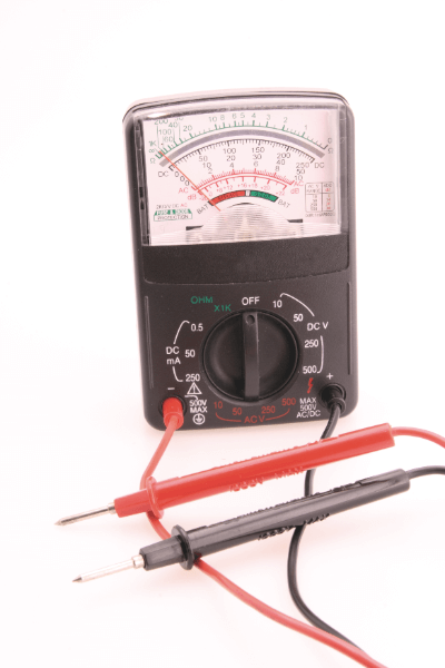
An AC millivoltmeter is a device used to measure AC voltage supplied from an AC power source.

In the past, many portable AC millivoltmeters were sold with only the function of an AC millivoltmeter, but in recent years, most AC millivoltmeters have been used as testers with multiple functions. There are two types of multifunctional products: analog testers and digital testers.

Analog testers have relatively low internal resistance, minimizing power loss. They also have the advantage of high accuracy and low measurement error.

Digital testers have high internal resistance and can measure circuits with high impedance.

Uses of AC Millivoltmeters

AC millivoltmeters are widely used in product inspection, maintenance, and preservation where AC current is used.

The following are examples:

  • Identifying the cause of audio equipment malfunctions
  • Confirmation of receiving and transmitting voltages of cubicles
  • Checking the condition of submersible pumps for drainage
  • Confirmation of output voltage of emergency generators
  • Confirmation of generating voltage at power stations
  • Confirmation of transmission and receiving voltage at substations

By using AC millivoltmeter, it is possible to identify the inherent voltages between electronic circuits.

As mentioned above, AC millivoltmeter is also used to monitor equipment voltage conditions.

Principle of AC Milivoltmeters

AC millivoltmeters can be broadly classified into two types: analog and digital.

Analog voltmeters mainly use the moving-piece method.
In the movable iron strip type, an input voltage is applied to a fixed coil, and the magnetic force generated in the coil moves the iron strip to oscillate the pointer. It is characterized by its simple structure and low cost.

The principle of a digital millivoltmeter is it first converts the input AC voltage to DC power via an AC/DC converter. The electrical resistance is then determined by the multiplier, and the amount of current flowing through the AC millivoltmeter is determined by the voltage of the bias current and the voltage of the AC millivoltmeter intrinsic resistance. With the electrical resistance and current determined, Ohm’s law can be used to determine the voltage.

Types of AC Millivoltmeter

As mentioned earlier, there are two types of AC millivoltmeters: analog and digital. Data loggers for logging voltages are also available.

Analog AC Millivoltmeter

Many people think of analog AC millivoltmeters when they hear the words “AC millivoltmeter. The most common type has a voltage plate and needle covered by a transparent acrylic cover on the front. Because of its simple structure, it is less prone to failures and more reliable than a digital AC millivoltmeter.

They are relatively inexpensive, and some are available on mail order sites for less than 10 dollars.

Digital AC Millivoltmeter

This type of voltmeter has a digital display on the front panel to indicate voltage. It has a control board such as FPGA inside and has functions such as an analog-to-digital conversion circuit.
The digital display is easy to read, and some are highly functional because various functions can be realized by the program that controls the board.

The price range varies from those priced in the 1o USD range to high-performance models, costing several thousand dollars.

Compared to analog, the structure is more complex, so the failure rate tends to be higher.

Data Loggers

A data logger is a type of device that has the function of an AC millivoltmeter and can simultaneously log the results of voltage measurements and perform various measurements, such as temperature, by connecting an expansion unit.

It is a type of device that can simultaneously perform various measurements, such as temperature, by connecting an expansion unit.

カテゴリー
category_usa

Laser Light Source

What Is a Laser Light Source?

A laser light source is a light source that emits laser light.

A laser is a highly directional light with a single wavelength and a high degree of photon wavelength identity. It has superior energy concentration compared to ordinary light. There are various laser light sources, ranging from semiconductor lasers suitable for projector light sources to YAG lasers, CO2 lasers, excimer lasers, and argon lasers suitable for cutting and processing objects. Lasers are classified into solid-state, semiconductor, and gas, based on the shape of the material they operate on.

Uses of Laser Light Sources

Laser light sources are used for a wide variety of means. The applications vary depending on the type.

1. Semiconductor Laser

Due to its long life and easy handling characteristics, it can be used as a projection light source for projectors.

2. YAG Laser

The YAG laser, a common solid-state laser, is used for laser processing, such as cutting and drilling of metals and various other materials; due to its optical characteristics, the YAG laser is not suitable for processing transparent materials.

3. CO2 Laser

In contrast to YAG lasers, CO2 lasers are suitable for processing transparent materials but are not suitable for processing metals.

Principle of Laser Light Sources

Laser light sources use as its light source light that is excited by giving energy to the molecules of the laser medium. When a laser source is given intense energy, a certain number of atoms in the laser medium enter an excited state.

  • Pumping
    An increase in the number of atoms in an excited state.
  • Inverted distribution state
    A state in which the number of atoms in the excited state exceeds the number of atoms in the other states due to pumping.
  • Optical amplification
    When an atom is irradiated with light of the same wavelength as the excitation light in the inverted distribution state, the atom receiving the light emits light of the same wavelength in the same direction as the light, causing other atoms to be excited.

Laser light sources are constructed with a mirror on the side where the light source is installed to cause light amplification and a partially reflecting mirror on the side where the laser light is emitted. The light excited by optical amplification is reflected by the partial reflection mirror and continues to reflect through the laser light sources while repeating optical amplification many times, finally passing through the transmission part of the partial reflection mirror as a high-energy laser beam.

Characteristics of Laser Light Sources

In addition to directionality, monochromaticity, and energy density, laser light sources have the characteristic of being in phase (waveform of light), which causes interference when they hit an object. This characteristic is used in laser interferometers and other distance-measuring instruments. Ordinary light is a mixture of various types of light with different phases, which makes interference difficult to occur.

Other Information on Laser Light Sources

Wavelengths of Laser Light Sources

There are various laser light sources, each of which can be classified by wavelength. Excimer lasers have wavelengths ranging from 150 to 308 nm, argon lasers from 488 nm, ruby lasers from 694.3 nm, YAG lasers from 1,064 nm, and CO2 lasers from 10,600 nm. The difference in wavelength is the difference in absorption rate when irradiated onto an object. Different absorption rates result in different temperatures.

Wavelength conversion is possible by using nonlinear optical crystals for the fundamental waves of the above lasers. For example, the fundamental wavelength of a YAG laser is 1,064 nm, and when passed through a nonlinear optical crystal, light with wavelengths of 532 nm at the second harmonic, 355 nm at the third harmonic, and 266 nm at the fourth harmonic can be extracted. It is also possible to create parametric oscillators with tunable wavelengths.

カテゴリー
category_usa

Camera Module

What Is a Camera Module?

Camera Modules

A camera module is an industrial device similar in structure to a consumer single-lens reflex camera.

A camera module can be divided into a lens and a camera. A part called a mount connects the lens to the camera, and the lens can be interchanged as long as the mounting standard is the same. There are two photographic elements in a camera: CMOS and CCD. There are also two image cropping methods: global shutter and rolling shutter.

Uses of Camera Modules

Small camera modules are used as cameras in smartphones and PCs, ATMs, and for facial recognition in vending machines and ticket machines. Large cameras are used as security, in-vehicle, and industrial equipment for inspection and measurement purposes.

Principle of Camera Modules

In-camera modules, light entering through the lens is formed into an image on the photographic element and converted into an electrical signal to acquire an image.

There are two main types of photographic elements: CMOS and CCD. CMOS can operate with low power consumption, while CCD has a global shutter, as described below. Both types of sensors convert light entering the photodiode into electrical signals, which are then converted into stable digital signals with noise suppressed by CDS, AGC, and ADS installed behind the photodiode. The digital signal is output as image data by the image processing engine.

The difference between a global shutter and a rolling shutter is explained below.

With a global shutter, light entering numerous photodiodes is converted into an electrical signal simultaneously. A rolling shutter converts light into electrical signals in a spiral-like sequence. In principle, a rolling shutter will take a distorted image of a subject tilted at an angle when capturing a subject that is moving quickly across the image. The images that can be acquired by the camera modules can be color or monochrome.

In a color sensor, photodiodes capable of discriminating a single color among the three colors blue, red, and green are arranged in a nested array called a Bayer sensor. A single photodiode can only obtain color information of a single color, but by obtaining information from surrounding photodiodes responsible for other colors, a single photodiode can pseudo-obtain information about all three colors.

Camera Modules Market

The global camera modules market is strong as of 2020 and is expected to continue to grow at a high rate.

Cameras in smartphones and other mobile devices began to shift to multi-cameras around 2015, evolving from single to dual, triple, and quad cameras.

In addition to higher image quality, AF, zoom, and wide-angle functions, the use of sensor camera modules such as ToF and LiDAR is expected to expand further, including improved AF performance in dark areas, improved face recognition accuracy, and use in virtual reality (VR) and augmented reality (AR) functions.

In the automotive market, the number of cameras installed per vehicle for advanced driver assistance systems (ADAS) is rising.

In the consumer electronics and industrial fields, demand is also expected to increase for the installation of smart products, assistant robots, and drones to meet the needs for manpower saving, security, and remote control.

The evolution of the lenses that make up camera modules, the use of new materials, and the development of technologies such as MEMS (micro-electro-mechanical systems) are increasing the value of camera modules.

Camera Modules for Automotive Applications

Demand for automotive camera modules is rapidly shifting from a focus on monitoring applications for peripheral blind spots that replace conventional mirrors to sensing applications, driven by growing demand for advanced safety assist systems (ADAS) and automated driving.

Together with advanced optics, image processing, and communication technologies, they play a major role in realizing a “safe and secure” automotive society.

There are various types of in-vehicle camera modules, as follows:

  • A Front Monitoring Camera Modules
    Monitors the car in the direction of travel and assists in safe driving.
  • Camera Modules for Drive Recorders
    Used to record video of the situation in front of and inside the vehicle at all times while the vehicle is moving or stopped.
  • Driver Monitoring Camera Modules
    Used to monitor the driver while driving and to predict hazards such as dawdling or falling asleep at the wheel.
  • Surround View Camera Modules
    This module is used to eliminate blind spots around the vehicle and to ensure safety.
カテゴリー
category_usa

Comparator

What Is a Comparator?

Comparator_1

A Comparator is an element that compares two input signals and produces different outputs depending on the results. Generally, two inputs are provided: an input of the signal to be measured and a reference signal.

This makes it possible to perform conditional branching in the circuit, such as to perform a specific operation when a signal (current or voltage) that exceeds the reference value is input.

The Comparator Input is Analog, but the Output Signal is Digital

Comparator_2

The input of the comparator is analog, but the output signal is digital. Therefore, comparators are sometimes used as an interface between analog and digital circuits.

Uses of Comparators

Comparators can be used to build logic circuits that perform comparisons between input signals (current and voltage) and reference signals. For example, they can monitor excessive rises or drops in voltage and alert you if they are out of range, or control the operation of equipment.

Other if/then conditional branching can also be performed, such as automatically adjusting the temperature of a refrigerator or air conditioner, or limiting the performance of a cell phone or PC when the battery is low.

Comparator Principle

A comparator has five pins, each consisting of a positive and negative power supply pin, two inputs, and an output pin. It has almost the same configuration as an operational amplifier, with the only difference being whether or not inverting amplification is performed. Originally, operational amplifiers have the property of outputting the voltage of the power supply when there is a difference in input voltage, and comparators make use of this property.

Conversely, if a circuit is built to apply feedback from the output terminal of a comparator to the negative input terminal, it can be used as an operational amplifier. Since comparators do not have a mechanism for inverting amplification, they do not provide phase compensation to prevent oscillation like operational amplifiers do.

Therefore, the most important feature of comparators is that comparators have superior responses compared to operational amplifiers. Moreover, if multiple comparators are used and the reference value is set in steps, they can be used as AD converters. AD converters with this structure can perform high-speed conversions.

Other Information on Comparators

Hysteresis Comparator

When a comparator has a single threshold for comparison, unexpected external noise superimposed on the analog signal causes the comparator to repeat High/Low in response to the noise. This causes a malfunction instead of switching with the original input value, so a comparator called a hysteresis comparator was invented.

Hysteresis comparators are characterized by having two threshold values depending on the output state. When the output switches, it switches to another threshold value different from the previous threshold value, thus preventing unexpected noise-induced malfunctions.

The circuit configuration of the hysteresis comparator applies positive feedback from the output terminal of a conventional comparator to the input terminal via a resistor or the like. Incidentally, this circuit is called a Schmitt trigger after the inventor’s name (Otto Schmitt).

Schmitt triggers are generally combined with active elements such as Zener diodes to prevent supply voltage fluctuations, making the circuit more versatile. The hysteresis comparator threshold can be set symmetrically plus or minus with respect to 0 V, or asymmetrically, but the important point here is that the hysteresis width should not be too large.

This is because a large hysteresis width improves immunity to external noise, but deteriorates the sensitivity to the input value that you originally want to judge. Therefore, care should be taken not to increase the hysteresis width beyond the actual noise value. For a more balanced design, the ratio of the threshold voltage to the comparator supply voltage should also be considered.

カテゴリー
category_usa

DIP Switch

What Is a DIP Switch?

DIP Switches

A DIP switch is a small switch used in printed circuit boards. They are tiny, with a distance of about 3 mm between terminals and a height of about 3 mm, and are switched with a precision screwdriver or the like. They are used as setting switches and are used for infrequent operations.

Operating methods include slide switches, push-lock switches, and rotary switches. Some types are inserted into a hole in the board or mounted on the board. Various types are available in terms of the number of poles and sealing performance.

Uses of DIP Switches

DIP switches are incorporated into a wide range of products, including home appliances, communications equipment, and audio equipment. In industrial applications, they are used in temperature controllers and servo controllers.

They are also used in office automation equipment, for example, in personal computers and storage boards. They are mainly used for basic settings of electronic equipment. To withstand a wide variety of usage conditions, various types are available, including heat-resistant types that can withstand high temperatures and low-profile types.

Principle of DIP Switches

Like an ordinary switch, DIP switches are used to switch on and off to conduct or disconnect circuits. A knob called a striker and a sliding element are interlocked, and the circuit is switched when the sliding element and the contact point make contact or open. The striker also serves as a weight that brings the slider and contacts into contact.

The contacts and terminals are molded together with the base resin. The base resin is made of highly heat-resistant plastic because it is subject to high temperatures during soldering. By molding the components as one piece, the size and weight can be reduced. The base resin also serves to protect the terminals.

There are two types of contact terminal shapes: those that are inserted into board holes and those that are surface-mounted. Since the switch is likely to be left unattended for a long period, gold plating may be applied to the contacts to prevent oxidation. Some products have a self-cleaning mechanism that cleans the contacts during sliding to remove foreign matter and oxides.

DIP switches are so small that a fine-tipped screwdriver or tweezers are required to switch them.

Types of Switches and DIP Switches

There are different types of switches for different applications. The following types of switches are used in a variety of industrial and consumer applications.

Types of Switches

  • Push Switches
    As the name suggests, this is a switch that is toggled by pushing a button.
  • Toggle switches
    A switch that is toggled by moving a lever up and down or left and right.
  • Rocker switch
    A switch that is toggled by pushing both ends of a button.
  • Slide switch
    As the name suggests, this switch is switched by sliding the button.
  • Rotary switch
    A switch that is toggled by turning a knob in the switch section.
  • Micro switch
    Switches that can be switched by a slight force.
  • DIP switch
    A switch mounted on a circuit board used for various settings of electronic devices.
  • Tactile switch
    A small switch mounted on a circuit board that energizes an electric circuit when a person pushes the switch in.

Types of DIP Switches

  • Slide type
    Switches by sliding the actuator. There are switches with flat or convex actuators.
  • Piano type
    Switches by pushing down the actuator. The lever can be short or long.
  • Rotary type
    The value is set by rotating the actuator. There are types in which the actuator is operated from the vertical upper surface of the board and others in which the actuator is operated horizontally.

Other than the actuator, there are various types depending on the mounting method, number of poles, and other characteristics.

Structure of DIP Switches

The structure of DIP switches consists of four parts: the cover, the striker, the slider, and the base. The cover is an injection-molded resin part that covers the top surface of the switch. It mates with the base to protect the internal mechanism.

The striker is the actuator of the switch. It transmits force to the slider to actuate the contacts. The striker is a movable contact made of a fabricated metal plate or other material. The base integrates the metal terminal and contacts by resin injection molding and is made of heat-resistant resin material.