カテゴリー
category_usa

Electromagnetic Field (EMF) Meter

What Is an Electromagnetic Field Meter?

An Electromagnetic Field (EMF) Meter is an instrument used to measure the strength of electric fields.

It is mainly used to measure the strength of radio waves received by radios and televisions, as well as to measure radio waves emitted by electronic devices. In recent years, there has been a significant increase in the us of electronic devices that emit radio waves.

The risk of radio interference among electronic devices and the potential impact of radio waves on the human body are both on the rise. As such, there is a great need for Electromagnetic Field (EMF) Meters that can accurately measure the electric field strength.

Applications of Electromagnetic Field (EMF) Meter

The Electromagnetic Field (EMF) Meter is designed to measure the strength of radio waves,  and so is used to investigate the installation location of devices that receive radio waves and to inspect the safety of devices that output radio waves.

When investigating the installation location of equipment that receives radio waves, EMF Meters are useful for assessing antenna installations for TV broadcast reception and identifying potential interference with TV reception. In recent times, there has been growing demand for measuring WiFi radio wave strength.

Electromagnetic Field (EMF) Meter is used in safety inspections of equipment that outputs radio waves. It helps to reduce the risk of radio interference from equipment that generates radio waves and ensure compliance with electromagnetic field bio-safety guidelines, minimizing potential adverse effects of radio wave on the human body.

Principle of Electromagnetic Field (EMF) Meter

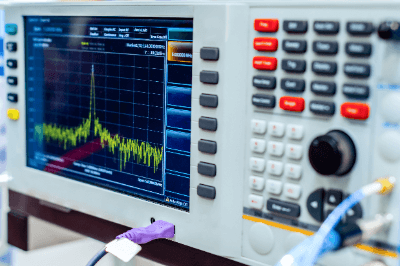
The most common method of measuring the strength of radio waves is to use an Electromagnetic Field (EMF) Meter to measure the voltage induced in an antenna with a known gain. The measured value is converted to an antenna with an effective length of 1 m and expressed in [dBμV/m].

1. Radio Wave Strength in Space

Electromagnetic Field (EMF) Meter has different measurement methods depending on the application. To measure the radio wave strength in a space, an electric field probe is simply directed towards the target device. Typically, the electric field probe uses an EO modulator (electro-optic modulator) to detect the intensity of the radio waves.

In the absence of an electric field, light input from a light source in the field probe passes through an optical fiber, is reflected by an EO crystal, and then passes through another optical fiber before being output.

However, when an electric charge is present, the EO crystal alters the refractive index of the light. Consequently, the output light exhibits a different refractive index than the input light. By converting the modulated light into intensity information using a photodetector, the Electromagnetic Field (EMF) Meter measures the strength of the electric field.

2. Radio Wave Absorption in the Human Body

In order to examine the radio wave absorption efficiency of the human body, etc., a device called a phantom must be inserted between the device under test and the electric field probe.

The phantom has the same electrical characteristics as the human body. The field probe of the Electromagnetic Field (EMF) Meter consists of an optical fiber, an EO crystal, and a glass tube covering it. The EO crystal exhibits the EO effect, in which the refractive index of light changes depending on the electric field present. The modulated signal is then detected by a photodetector.

Other Information on Electromagnetic Field (EMF) Meter

1. Electromagnetic Field (EMF) Meter Kits

The major difference between commercially available inexpensive assembled kits of Electromagnetic Field (EMF) Meter and those sold by the manufacturer is the significant difference in performance, convenience, and versatility. For example, in the case of inexpensive kits, the display is an analog pointer meter.

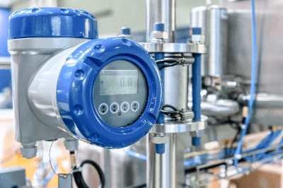
On the other hand, the manufacturer’s Electromagnetic Field (EMF) Meter has a color LCD display, can store the obtained data in memory, and can communicate with other devices. Therefore, it can be said that Electromagnetic Field (EMF) Meter kits are more for educational or temporary use.

2. Electromagnetic Field (EMF) Meter App

In recent times, WiFi signal strength can be measured with Electromagnetic Field (EMF) Meter apps. However, a little care is needed in the settings. When setting up a wireless network, the coverage area will hardly change.

However, the signal strength is weakened as it passes through obstacles like furniture and walls. So is interference caused by other wireless networks in the vicinity, causing the WiFi signal to progressively weaken as one move away from the source router.

When users get a strong signal, they get fast page loads and instant downloads. In order for the router to send a strong signal where it is needed, it is important to choose the right location and configuration of the router for the best results.

Recently, there are apps that display a visual map of the router wireless range. These apps also show information about other WiFi networks and the field strength of the WiFi signal. They visualize the signal strength of the wireless network as a handy heat map to assist in determining where to place the router.

カテゴリー
category_usa

Encoder

What Is an Encoder?

Encoders

An encoder is a device that converts changes in position into electrical signals and outputs them.

Encoders that measure rotation angle are called rotary encoder, while those that measure linear displacement are called linear encoder.

Methods for measuring position change can be classified into incremental and absolute methods. Light, magnetic force, electromagnetic induction, etc. are commonly used for measurement.

Uses of Encoders

Encoders are mainly used in machines that use motors, among which stepping motors and servo motors are typical motors that use encoders.

1. Stepping Motors

Stepping motors are motors whose rotational speed and angle can be accurately controlled by pulse signals.

The interval between pulses and the number of pulse signals applied to the motor determine the angle and speed of rotation, enabling accurate positioning, which is why stepping motors are used in manufacturing and other fields.

Not all stepping motors use encoders. There are two types of stepping motors: open-loop stepping motors, which do not use encoders or feedback control, and closed-loop stepping motors, which use encoders and feedback control.

The open-loop method is a simpler system than the closed-loop method, but it always applies the maximum current to prevent “stalling,” which is the inability to keep up with the pulse speed.

2. Servo Motors

A servo motor is a motor that has a mechanism to maintain a constant speed of continuous linear or rotational motion by precisely controlling the distance traveled and angle of rotation in a single control.

It is a three-piece set consisting of encoders, a brushless AC motor (the mainstream) or a DC motor, and a servo amplifier. AC motors are currently the most common type of motor used in machines that require precise motion control. Examples include industrial robots, automobiles, elevators, and automatic guided vehicles. They are used in many factories, especially now that factories are becoming more and more automated.

When selecting encoders, consider measurement accuracy, resolution, reaction time, size and shape, durability against vibration and shock, and protection against the operating environment.

Principle of Encoders

Encoders are classified into optical, magnetic, and electromagnetic induction types according to the detection method.

1. Optical Encoders

Displacement can be measured by shining light on a rotating disk with evenly spaced holes attached to a rotating shaft and detecting the period of light passing through the holes. Since light has little effect on machines, it is widely used in general.

Optical encoders can be classified into two types according to the output signal: incremental and absolute. Each method is explained below.

  • Incremental method
    The incremental method measures position displacement by measuring the number of times light passes through a hole in a rotating disk.
  • Absolute method
    The absolute method measures position displacement by detecting absolute position signals assigned to each hole of the rotating disk.

2. Magnetic Encoders

Displacement is measured by utilizing the magnetic field of a magnet attached to the rotating shaft, which fluctuates due to rotation.

3. Electromagnetic Induction Encoders

Displacement is measured by detecting electromagnetic induction generated by a coil mounted around a rotating shaft.

カテゴリー
category_usa

Flowmeter

What Is Flowmeter?

flowmeter

A Flowmeter is a device used to measure the volumetric or mass flow rate of a fluid flowing through a pipe.

Many measurement principles have been developed to properly measure various types of flow depending on conditions such as pressure and temperature. Flow types include gas, liquid, and multiphase flows.

Some products can be installed outside of the piping to measure flow. However, many flowmeters are designed to be installed inside the piping for flow measurement. Therefore, the installation of a flowmeter should be carefully considered either before the piping is installed or during the design phase.

Uses of Flowmeter

Flowmeters are widely used in manufacturing where fluids are used, including chemical and petroleum plants, automotive, semiconductor, pharmaceutical, and food industries.

More than ten (10) different operating principles have been developed for flow meters, and the appropriate flow meter must be selected according to the fluid being handled.

Flowmeters installed in pipes can disrupt the flow. Therefore, the selection should be based on consideration of the extent of this impact. The frequency, time, and cost of maintenance should also be considered.

Types of Flowmeters

The following is a brief introduction to the types of flowmeters and their respective mechanisms, principles, and advantages.

1. Positive Displacement Flowmeter

A positive displacement flowmeter consists of a pipe with the same inside diameter as the piping to be measured, a rotor, and a rotation detector. The fluid flowing through the pipe rotates the rotor, and the flow rate is measured by detecting the rotation speed.

The structure is simple and highly accurate, but the use of gears can lead to problems such as entanglement.

It is used for for measuring the flow rate of fluids like fuel oil and lubricating oil, which have relatively stable densities. Due to its high accuracy, it is well-suited for applications such as fuel oil trading.

2. Coriolis Flowmeter

The Coriolis flowmeter consists of two U-tubes, a vibrating machine, and a force sensor. The Coriolis flowmeter utilizes the principle of Coriolis force, in which two oscillating U-tubes with fluid flowing through them generate forces in opposite directions to each other.

While the Coriolis flowmeter has the disadvantage of being long due to its measurement principle, it does well at directly measuring mass flow. It has high accuracy and responsiveness, and is widely used when the density of a fluid is also to be measured at the same time.

On the other hand, it is less effective in environments with vibrations or when measuring fluids that contain bubbles.

3. Ultrasonic Flowmeter

An ultrasonic flowmeter consists of an ultrasonic generator and a measuring instrument. The flow rate is calculated by measuring the propagation time of ultrasonic waves and the Doppler effect caused by the reflection of ultrasonic waves. This flowmeter can measure from the outside of the piping.

It has the advantage of non-contact fluid flow measurement, allowing the flowmeter to be retrofitted onto existing piping. It can also be installed cost-effectively, even on large-diameter piping.

However, it is not well-suited for applications that require highly accurate flow measurement due to errors caused by factors such as pipe wall thickness.

4. Electromagnetic Flowmeter

Electromagnetic flowmeter calculates the flow rate by measuring the electromotive force generated by the coil component within the device. This electromotive force is influenced by the velocity of a magnetic material placed inside the fluid to be measured.

Many of these meters do not need to be installed in the pipe, and are used when maintenance costs for in-pipe flowmeters, such as those used for contaminated water, are high.

Electromagnetic Flowmeter is used to measure the flow rate of slurry mixed with solids because it has no moving parts and does not obstruct the flow of fluid. However, it cannot measure non-conductive fluids, such as oil.

5. Thermal Flowmeter

A thermal flowmeter consists of two temperature sensors and a heater. It calculates the flow rate by measuring the difference between the fluid’s temperature before and after it is heated by the heater. This measurement is then converted into a flow rate. The thermal flowmeter is known for its ability to handle a wide range of temperatures.

Thermal flowmeter can measure corrosive gases since it is a non-contact gas flowmeter. In addition, there is almost no pressure loss and mass flow rate can be measured. However, it may not be suitable for the measuring theflow rate of gases that already contain contaminants.

6. Area Flowmeter

In an area flowmeter, a float within a vertically tapered tube interrupts the flow from bottom to top, resulting in a pressure difference before and after the float. The meter rests at a position where the weight of the float and the force of the pressure difference are balanced. By reading this position, the flow rate can be determined.

It is used to measure the flow rate of liquids, gases, purge fluids, and more. Its straightforward construction makes it cost-effective, although it does not provide very high measurement accuracy.

7. Turbine Flowmeter

The turbine flowmeter is positioned within the flow and calculates the volumetric flow rate based on the number of revolutions of the impeller. It utilizes the fact that the rotational speed of the impeller, which has an axis parallel to the flow, is directly proportional to the flow velocity.

The lightweight design allows for a high degree of freedom in installation. Due its lightweight, inexpensiveness, excellent repeatability, and responsiveness, it is well-suited for measuring large volumes of fluid. However, it has a short-service life due to bearing deterioration.

8. Differential Pressure Flowmeter

Differential pressure flowmeter uses an orifice to create a pressure loss and measures the flow rate by utilizing the pressure difference between the primary and secondary sides.

It is characterized by its low-cost and wide range of applications. Actual flow calibration is not required.

9. Karman Vortex Flowmeter

The Karman vortex flowmeter consists of an obstacle designed to generate Karman vortex and a vortex measuring instrument. The flow rate is calculated by measuring the Karman vortex.

Karman vortex is a regular vortex generated in the wake of an obstruction.

Karman vortex flowmeter can measure a wide range of fluids since there are no mechanical operating parts or electrodes. However, it cannot be used in high-vibration environments due to the length of straight pipe required and the possibility of malfunctions caused by vibration.

It is used to measure steam and clean water.

10. Vortex Flowmeter

A vortex flowmeter is a flowmeter that uses the Karman vortex. A Karman vortex is an alternating sequence of regular vortices that occur downstream of an object (vortex source) placed in the fluid flow.

11. Flow Cell Flowmeter

A flow cell flowmeter is a type of orifice flowmeter that generates differential pressure by installing an orifice in the piping through which water or air flows and measures the differential pressure using a float installed in the tributary stream.

カテゴリー
category_usa

Line Scan Cameras

What Is a Line Scan Camera?

A line scan camera is a camera that captures an object in a line and combines it into a single image.

Area sensor cameras, which are often compared, capture the entire field of view at once.

A line scan camera captures a flat image by continuously moving the object perpendicularly to a row of line sensors, or by moving the camera.

Unlike an area sensor camera, a line scan camera can capture slight pixel-by-pixel changes when acquiring a horizontal image.

Uses of Line Scan Cameras

Objects for which line scan cameras are suitable include those that are large, require high precision resolution, are long and continuous, and have a three-dimensional appearance.

For example, when photographing a large object, an area sensor can be used to take pictures by dividing the object into sections, but in this case, multiple images must be stitched together. On the other hand, using a line sensor, the image can be captured as a single image and does not need to be stitched together.

Specifically, line scan cameras are used for a wide range of purposes, from inspections of social infrastructure such as roads and exterior walls to industrial inspections of non-woven fabrics, gears, semiconductor parts, etc. In addition, they are also used in the analysis of works of art, and in the sorting of fruit that had previously been inspected visually.

Principle of Line Scan Cameras

Like an ordinary camera, a line scan camera converts light entering through a lens into an electronic signal by forming an image on a CCD, CMOS, or other imaging element and outputs the signal as an image.

The camera continuously captures images by moving the subject vertically to the imaging element, which consists of a single row of line sensors. Many images are then combined to obtain a continuous image.

Line scan cameras can be broadly classified into models that can acquire monochrome images and models that can acquire color or invisible ray images.

Models that can acquire color images have about 1~3 rows of line sensors and are multilayered. This is because only one color’s information is available from each sensor.

In a 3-row color sensor, a particular pixel is captured by three image sensors that can acquire blue, green, and red color information. On the other hand, with a single-row color sensor, only a single pixel is captured by a single image sensor, so only a single color’s information is acquired. And since the color information of one specific pixel is estimated from the surrounding color information, the color accuracy is inferior to that of a three-row color sensor.

Selecting Line Scan Cameras

What is important in selecting line scan cameras is to make a total judgment of the resolution, exposure control, high-speed compatibility, sensitivity, and other factors of the target system to be handled.

1. Exposure Control

Old line scan cameras do not have exposure control, and the brightness of the light source is manually changed in response to speed fluctuations. By using an electronic shutter, the exposure time can be automatically changed to capture images at the same brightness even if the speed changes.

2. High-Speed Support

This is judged by throughput, which represents data processing capacity. Cameras with the highest speed level are now commercially available.

3. Sensitivity

Conventional line scan cameras require a strong light source because they can only take an exposure time of one line scan. Therefore, the sensor itself is highly efficient with an aperture ratio of 100%. Some cameras use time-delay integration technology to increase sensitivity by dozens of times or more, making them suitable for locations where light levels cannot be increased or for high-speed scanning.

4. Shading Correction

Modern cameras can compensate for small differences in sensitivity within a pixel in real-time in the camera. With this tool, shading correction, which is the correction of light intensity variation in the width direction due to uneven illumination, can be performed.

カテゴリー
category_usa

Spring Contact Probe

What Is a Spring Contact Probe?

A spring contact probe is an electrically conductive probe.

A spring contact probe can be used to inspect the continuity of printed circuit boards and electronic components without the need for soldering, connector connection, or other fixing. The shape of the probe can be selected according to the inspection target.

The spring-loaded structure allows the probe to make contact with the electrode to be inspected with an appropriate load.

Uses of Spring Contact Probes

A spring contact probes are used for continuity testing of electronic components.

The inspection targets include semiconductors, liquid crystal panels, circuit boards, connectors, capacitors, sensors, batteries, and other components.

In addition to simple inspections of disconnections and shorts in these components, spring contact probes can be used in a wide range of applications, such as current flow and high-frequency measurement. For example, to inspect ICs, spring contact probes are placed on the printed circuit board on the side of the inspection equipment and contacts the IC from above, enabling quality inspection without fixing it in place.

カテゴリー
category_usa

Oscilloscope

What Is an Oscilloscope?

Oscilloscope

An oscilloscope is an instrument that outputs electrical signals as waveforms on a screen, and is characterized by the ability to observe signal changes over time in two dimensions.

Oscilloscopes are broadly classified into analog oscilloscopes and digital oscilloscopes.

1. Analog Oscilloscopes

Analog oscilloscopes observe input signals by scanning an electron beam over the tube surface of a cathode-ray tube to draw waveforms. The input signal to the oscilloscope is immediately displayed with a short delay.

2. Digital Oscilloscopes

Digital oscilloscopes convert input signals into digital data using an A/D converter, store the data in memory, and then display the waveforms on a display. Unlike analog oscilloscopes, data collection is discrete, so data is complementary and displays as a smooth curve.

Uses of Oscilloscopes

Oscilloscopes display electrical signals as waveforms, allowing you to visually check the operation of electronic circuits. By using an oscilloscope, it is possible to check the signal waveforms in an electronic circuit and verify that the circuit is operating as intended.

When verifying high-speed digital circuits, signals must be captured with reliable timing that is not affected by digital signal fluctuations (jitter), and oscilloscopes are used to set the timing.

Oscilloscopes are also useful in repairing electronic equipment because they can trace the signal waveforms of various parts of an electronic circuit to locate the faulty part if the cause of the equipment failure is in the electronic circuit.

Principle of Oscilloscopes

In a conventional analog oscilloscope, the signal input from the probe is transmitted to the oscilloscope’s vertical amplification circuit. The signal is attenuated or amplified in the vertical amplifier circuit and then transmitted to the vertical deflector plate of the cathode-ray tube.

The voltage applied to the vertical deflector plate scans the electron beam up and down. This sequence of events is the principle behind oscilloscopes. The input signal is simultaneously transmitted to the trigger circuit, and the electron beam starts scanning horizontally the moment the signal matches the set trigger condition.

In a digital oscilloscope, the input signal is converted to digital data by an A/D converter, and the data is sequentially stored in memory. Then, after a predetermined period has elapsed from the point when the input signal meets the trigger condition, it stops storing new data.

As a result, the above memory records the signals before and after the timing when the trigger condition is met, and these signals are displayed as waveforms on the display. In other words, signal waveforms before the trigger can also be observed.

The data in the memory can also be used for waveform analysis, e.g., frequency analysis of signals by FFT operation. Furthermore, the data can be output to a memory card for analysis and data storage on a PC.

How to Select an Oscilloscope

When selecting an oscilloscope, it must have sufficient specifications for the application. Specifically, frequency response, sampling rate, number of channels, memory length, and available probe types should be considered.

In addition to the basic use of oscilloscopes for observing waveforms, current oscilloscope applications are expanding to include timing verification, waveform analysis, and compliance testing, and the measurement range and functionality are increasing accordingly. As a result, there is a need to select a model with functions suitable for the intended use.

How to Use an Oscilloscope

In addition to observing voltage variations over time, oscilloscopes can also measure the frequency of repetitive signals and draw Lissajous curves. Oscilloscopes are widely used for testing electronic circuits, waveform visualization of video and audio signals, testing response characteristics of power devices, measuring the timing margin of high-speed digital circuits, and evaluating mechatronics products.

Preparation for measurement includes phase adjustment of probes and skew adjustment between probes. Especially when current and voltage probes are used together, skew adjustment is essential because of the significant delay time of current probes. One should also wait about 30 minutes after power-on before measuring to ensure sufficient measurement accuracy.

The trick to observing the desired waveform is to adjust the trigger. With analog oscilloscopes, the only adjustment factors are slope selection, trigger level, and trigger delay, but with digital oscilloscopes, in addition to these factors, various trigger conditions, such as pulse width and interval, can be set.

Additionally, sequential triggers, which capture signals when multiple trigger conditions are satisfied, are also available.

Other Information on Oscilloscopes

1. Features and Differences Between Analog and Digital Oscilloscopes

The features of both types of oscilloscopes can be summarized as follows:

Analog Oscilloscope

  • Excellent real-time performance and short dead time between capturing and displaying a new signal.
  • The frequency of occurrence of the same waveform can be determined by the brightness of the signal.
  • Not suitable for observation of one-shot phenomena or phenomena that are not frequently repeated.
  • Requires photographic equipment to save observation results.
  • Analysis using waveforms is not possible.

Digital Oscilloscope

  • The supplemental display of one-shot phenomena is possible.
  • Observation results can be handled as electronic data for easy storage.
  • Waveforms can be handled as digital data and analyzed by a processor.
  • Long dead time for signal processing, so actual observation time is relatively short.
  • Waveform frequency information is lost in repetitive waveforms.

Today, there are no analog oscilloscopes available for industrial measurement applications, and digital oscilloscopes are the choice for almost 100% of applications.

This is possible because of readily available high-speed A/D converters and processors for waveform processing, along with tech improvements that address digital oscilloscope limitations, resulting in affordable, highly functional products.

2. Points to Note About Oscilloscopes

There are several points to note when using an oscilloscope to observe correct waveforms. In particular, it is important to select a model with a frequency response that sufficiently covers the frequency band you wish to measure.

The frequency response of an oscilloscope is defined as the frequency at which the amplitude falls to -3 dB. So, for accurate amplitude measurement, a model with a frequency response of about 5 times the frequency of the signal under test should be selected.

Additionally, the data sampling frequency of a digital oscilloscope must also be taken into consideration. If the sampling frequency is less than twice the frequency of the signal under test, aliasing will occur and false waveforms will be displayed.

カテゴリー
category_usa

Logic Analyzer

What Is a Logic Analyzer?

Logic AnalyzersA logic analyzer is a device primarily used to verify the operation of digital circuits.

They are sometimes compared to oscilloscopes, which are mainly used for analyzing analog signals.

Uses of Logic Analyzers

Logic analyzers are essential tools for verifying and troubleshooting digital circuits and are used in product development and manufacturing.

For multiple signal inputs, analog characteristics are not measured, but converted to 0s and 1s using threshold values for further processing. Since signals are treated as digital data, logic analyzers are used in the following applications:

  • Debugging and verification of system operations.
  • Simultaneous tracking and correlation of multiple digital signals.
  • Detection of timing violations and transients on buses.
  • Tracing the execution of embedded software.

Logic Analyzer Principles

A probe is connected to the measurement point of the system under test (SUT) and the signal is transmitted to the logic analyzer, first passing through the internal comparator.

The comparator compares the signal to a threshold voltage set by the user, and if the measured voltage exceeds that of the threshold voltage, the signal is transmitted to the next stage as a 1; if the voltage is lower than the threshold voltage, the signal is transmitted as a 0. In other words, after passing through the comparator, the signal is treated as digital.

The result is output as a digital signal corresponding to the clock and trigger conditions. The clock can be either the internal sampling clock of the logic analyzer or the SUT’s clock, depending on the application.

The former is done to obtain timing information between each signal, and the latter to obtain state. Trigger conditions can be set for various items such as specific logic patterns, number of events, and event duration.

It is important to set appropriate threshold values based on the signal level of the circuit being tested, and to set appropriate clock and trigger conditions for the information to be obtained.

How to Use the Logic Analyzer

Connect the probe to the SUT and set names for individual input signals. When measuring multiple signals such as buses, it is easier to observe the measurement results if they are grouped and registered.

Next, determine the sampling time. The higher the sampling clock frequency, the more detailed the signal measurements become. On the other hand, the amount of data that can be captured is constant, so the time range that can be observed becomes narrower. The signal sampling interval can be obtained from the following equation.

Sampling interval (sec) = 1/frequency (Hz)

Finally, set trigger conditions. In addition to defining triggers, the display method for when a trigger occurs can be specified. This allows you to specify whether to stop sampling after a trigger occurs once or to update the results each time a trigger occurs.

Other Information on Logic Analyzer

1. The Difference Between a Logic Analyzer and an Oscilloscope

While oscilloscopes can observe analog characteristics such as signal waveforms, logic analyzers handle digital data from signals.

Although oscilloscopes provide more information from a single signal, they can only observe about four signals simultaneously, whereas logic analyzers can handle many input signals at the same time. 

2. Points to Note When Using a Logic Analyzer

There are a few precautions to take when using a logic analyzer to prevent damage to the SUT or logic analyzer itself and to obtain accurate measurements.

Make sure the SUT is turned off.
When connecting a probe to the SUT, there is a risk of contact between the measurement point and its surroundings via the probe; if the SUT is powered, a large current may flow at that moment and cause failure. Therefore, the SUT should only be turned on after the probe is connected.

Select the probe appropriate for your application.
There are three types of probes:

  • Flying-lead probes connect a separate lead to each signal to be measured.
  • Connector probes connect to a connector dedicated to the logic analyzer.
  • Connectorless probes connect directly to the footprint of the board.

Select the probe that best suits your application.

Set the measurement conditions according to the application.
Set the sampling clock and recording time according to the frequency of change of the signal to be measured and the measurement range. Depending on the performance of the logic analyzer, select the settings and model to obtain correct measurement results based on the resolution and memory capacity.

カテゴリー
category_usa

Solder Pot

What Is a Solder Pot?

Solder PotsA solder pot is a container that holds or is filled with molten solder and equipped with a heater to keep the solder in a molten state.

Depending on the shape and quantity of the object to be soldered, solder pots range in size from tabletop units for use in laboratories to large units for use on production lines.

There are two types of solder pots: stationary units, in which the solder remains stationary inside the pot, and jet-flow solder pots, in which there is a nozzle inside the pot and the solder flows out in jets.

Uses of Solder Pot

Solder pots are well suited for tasks such as soldering leads and mounting components on printed circuit boards. While soldering may be done manually, solder pots are useful for efficiently soldering large volumes of simple, stable objects and achieving consistent results.

Principle of Solder Pots

Solder pots consist of a container for storing molten solder and a heater for keeping the solder in a molten state. Their basic structure is simple, but most solder pots used in production environments are equipped with a conveyor that can precisely control the temperature of the solder pot and transport objects into it.

The molten solder in a solder pot oxidizes when exposed to air for a long period of time. Oxides deteriorate the wettability between the solder and the base metal to be soldered, which is a major cause of solder defects.

It is important to always supply molten solder that is not oxidized to achieve good results. This is why jet-flow solder pots, in which a nozzle spurts molten, unoxidized solder from inside the solder pot into contact with the base metal, are often preferred.

Although measures to remove oxides are necessary with both stationary and jet-flow solder pots, oxides are less likely to form when using the latter because the solder is always flowing, reducing the amount of work required to remove oxides.

1. Soldering Using a Stationary Solder Pot

Molten solder is placed in the solder pot, and the component to be soldered is immersed in the molten solder. Soldering is completed when the component is pulled out.

2. Soldering Using a Jet-Flow Solder Pot

Jet-flow solder pots are equipped with a nozzle that is used to spray molten solder onto the component.

This method has become widespread in the field of printed circuit board manufacturing. An example of a common automated process is when a chip is built into a printed circuit board, and transported to the solder pot by a conveyor, where jets of molten solder mount it in place.

Other Information on Solder

1. Types of Solder

When using solder, a flux is used to ensure a clean soldering process.

Flux is a liquid containing ammonium chloride or zinc chloride. It is used to remove impurities from the printed circuit board and clean the surface of the board so that it can be soldered cleanly. It is also used to prevent oxidation of the copper wiring on the board surface.

Rosin is a component of pine tar that acts as a flux. It is often incorporated into solder called rosin core solder.

2. Solder Material

Solder is an alloy consisting mainly of lead and tin. Solder is mainly used to make metal bonds between various electronic components and connectors mounted on printed circuit boards, which constitute electronic circuits, and the wiring on the printed circuit boards to enable the conductivity of the components and connectors. Another common application is to facilitate metal bonding between pipes.

The history of solder dates back to around 3000 BC in Mesopotamia. Silver-copper or tin-silver solder was used to attach silver handles to copper vessels. Later, during the Greek and Roman periods, tin-lead solder, which is now the mainstream solder, was used for joining water pipes.

Later, the toxicity of lead became apparent, and the EU became the first country in the world to regulate the use of tin-lead solder via the Rohs Directive of 2006. Today, solder and electronics manufacturers around the world are taking the lead in developing lead-free solders, which are now widely used. Currently, the main solder alloys are tin-silver-copper, tin-copper-nickel, and tin-zinc-aluminum, none of which contain lead.

3. Solder Temperature

The temperature of solder varies depending on the solution, but the melting point of lead-containing solder is 183 °C and that of lead-free solder is around 210 °C. Lead-free solder has a higher melting point, making it more difficult to melt and spread.

However, products comparable to the conventional tin-lead type have now been developed, and the melting points of tin-silver-copper (Sn 96.5%, Ag 3%, Cu 0.5%) and tin-copper-nickel (Sn 99%, Cu 0.7%, Ni and other additives) alloys, which are some of the most common lead-free solders, are 217-227 °C.

カテゴリー
category_usa

Vibration Tester

What Is a Vibration Tester?

A vibration tester is a testing machine that applies vibration to parts or products.

The main purpose is to check for damage or failure caused by vibration. It is also used to examine the vibration response characteristics of components.

Any product can be damaged due to fatigue caused by vibration over a long period. Therefore, vibration tester is often used for quality assurance purposes.

A vibration tester is mainly used to check vibration resistance performance by sinusoidal or random wave vibration. They are also used to measure mechanical impedance, which is the vibration response characteristic of a mechanical system, to determine resonance frequencies and vibration countermeasures.

Uses of Vibration Testers

Vibration testers are used to confirm the vibration resistance of parts and products and to determine the vibration response characteristics of components and structures.

Principle of Vibration Testers

Vibration testers are classified into mechanical, hydraulic, electrodynamic, servo motor, and other types depending on the drive system. The classifications are as follows.

1. Mechanical Vibration Testers

This method uses a motor as the driving force to mechanically convert rotational motion into reciprocating motion. Compared to hydraulic and electrokinetic types, mechanical vibration testers are relatively inexpensive. In recent years, mechanical vibration testers have been replaced by other methods due to their shortcomings in controllability. 

2. Hydraulic Vibration Testers

This method uses hydraulic pressure from a hydraulic pump as the driving force. The servo valve switches the hydraulic circuit at high speed to generate vibration. This method is suitable when low vibration frequency, long stroke, and high power are required. The frequency range is 1 to 300 Hz. It is often used when large structures such as buildings are vibrated by seismic waves.

3. Electrokinetic Vibration Testers

This method utilizes the Lorentz force generated when an electric current is applied to a conductor in a magnetic field. By bypassing an alternating current through a drive coil installed in a magnetic field with an excitation coil, a reciprocating motion is generated in response to the current. The vibration of the shaker is detected by a pickup and fed back to the controller to keep the vibration at a set value. This method is characterized by a wide range of vibration frequencies and can be used up to particularly high vibration frequencies. The vibration frequency range is generally from 5 to 3,000 Hz, but some small shakers are capable of higher frequencies, up to 40,000 Hz. 

4. Servo Motor Type Vibration Testers

This method uses a servomotor linear actuator that combines an AC servomotor and a ball screw to generate vibration. The load capacity is lower than that of the hydraulic type, and the frequency range is lower than that of the electrodynamic type. The operating range is intermediate between the hydraulic and electrodynamic types. The frequency range is 0.01 to 300 Hz.

カテゴリー
category_usa

Leakage Current Meter

What Is a Leakage Current Meter?

A leakage current meter is a device that measures leakage current from electrical equipment. Generally, it is a clamp meter that can measure minute currents of mA or less.

Uses of Leakage Current Meters

Leakage current meters are used in electrical equipment and medical devices. Generally, they are used to determine whether they conform to the standards outlined in laws and regulations.

Leakage current has a significant impact on the human body, and even a weak leakage current can lead directly to death, so accurate measurement is necessary from a safety perspective. It is also important from the viewpoint of quality because it can cause noise in communication equipment.

Principle of Leakage Current Meters

Leakage current meters are capable of non-contact measurement with circuit conductors and measure current by clamping a copper wire with a clamp meter.

The principle of current detection is to detect the magnetic field generated by the current and extract an output proportional to the measured current. The most common detection methods include the CT method, Rogowski coil method, Hall element method, and fluxgate method.

The principle of each method is as follows.

1. CT Method

This method converts the current to be measured into a secondary current corresponding to the turn ratio.

2.Rogowski Coil Method

This method converts the voltage induced in an air-core coil by an alternating magnetic field created around the current to be measured.

3. Hall Element Method

This method combines the Hall element and CT methods to measure from DC current.

The Hall element is an element that measures the voltage generated when a current flows through a point where a magnetic field is generated, and this method is the mainstream for DC measurement.

4. Fluxgate Method

This method combines the fluxgate (FG element) and CT methods to measure DC current.
The fluxgate is an element that measures the magnetic field generated by winding two coils in opposite directions around an iron core and calculates the current value backward from the magnetic field.

Difference Between Leakage and General Ammeters

The most important feature of a leakage current meter is its resolution.

Ammeters that measure load currents measure large currents of 1A or more in the case of the clamp method. leakage current meters, on the other hand, need to measure weak currents, so they can only measure weak currents of 1A or less.

There are load current meters that measure weak currents for semiconductor manufacturing processes, but for such applications, devices that are connected in series to a circuit are commonly used.