カテゴリー
category_usa

Torque Motor

What Is a Torque Motor?

A torque motor is a type of motor that provides high starting torque, decreasing as rotational speed increases. It operates stably across a broad speed range, making it ideal for rollers and winding devices. Torque motors are particularly effective at low speeds, where high torque is essential for tasks such as winding, where initial low torque and high speed are needed, transitioning to high torque and low speed as the diameter of the wound material increases.

Uses of Torque Motors

Torque motors are integrated into equipment for constant-speed winding of sheet materials like cloth, paper, rubber, or linear materials such as metal wire, cable, or thread. They are utilized in applications requiring constant tension, including feed rolls, compensation for roll tension loss, small cranes, belt conveyor drives, as well as for tightening valves and screws, and automating door movements.

Principle of Torque Motors

The RPM-torque characteristic curve of a torque motor, unlike other motors, steadily decreases, showcasing a droop characteristic. This allows the torque to decrease with increasing rotational speed to maintain balance with the load. By adjusting the applied voltage, this droop characteristic can be tuned, making torque motors adaptable for applications requiring static torque for constant angular velocity operations. They are also efficient for tasks needing frequent starts and stops due to their high starting torque and low starting current requirement.

Other Information on Torque Motors

How Torque Motors Are Used as Brakes

Torque motors can also function as brakes to maintain constant tension in unwinding applications, utilizing their braking characteristics in two main ways:

1. Reverse-Phase Braking
Utilizes the torque generated when the motor rotates against the direction of the applied AC voltage’s magnetic field. This braking force is effective from zero rotation speed, making it suitable for maintaining tension even when the motor is stopped.

2. Eddy Current Brake
Employs the braking force generated by the eddy currents when a DC voltage is applied, working independently of the motor’s rotation direction. The brake force increases with rotation speed, stabilizing at higher speeds, ideal for maintaining tension in both forward and reverse directions at high rotational speeds.

カテゴリー
category_usa

Impact Tester

What Is an Impact Tester?

An impact tester is a testing machine used to perform impact tests.

In impact testing, we confirm that the products we use have sufficient strength when subjected to impact, and in the event of breakage, we confirm the type of breakage that occurs. Some of the products we use in our daily lives have components that are used under impact loads or are subjected to impact due to accidental factors. To maintain product safety, it is essential in product development to evaluate the durability and breakage of products under impact loads.

There are two main categories of impact testing. The other is the impact strength of the product itself and how it breaks when subjected to impact.

Most of the tests standards are classified into the former category. In these tests, the amount of distortion, expansion, shrinkage, flatness, surface cracks, etc. are measured when a sample is subjected to impact.

Uses of Impact Testers

Impact testers are used to evaluate whether or not, or to what degree, a product, its components, or its materials have the specified impact strength. Impact Testers are used to verify the impact strength of metal materials and resins, and the strength of industrial products to impact loads.

Smartphones, which are indispensable in our daily lives, are not usually subjected to impact loads. However, it is possible for them to be dropped by accident. Impact Testers are used to confirm that a product will not break even if it is accidentally dropped, and to determine the type of breakage that may occur.

Principles of Impact Testers

There are various impact testers, each of which has its own testing machine. The common principle of the impact tester is that the test specimen and test method are specified to ensure repeatability of the test.

Impact testers apply an impact load to the test object, and it is important that the same conditions are applied when the test is repeated. While the impact test may result in significant plastic deformation or even cracking of the test object, slight differences in the impact load can significantly alter the results.

Variations in the test object itself may also have an effect. Therefore, the test method is defined from the viewpoint of how the same impact load can be repeatedly applied and how the test can be performed with high reproducibility.

Other Information on Impact Testers

Types of Impact Tests

The following three types of impact testing are typical. 

1. Izod Impact Tester
In the Izod impact test, one side of a specimen is fixed and the other side is impacted to measure the impact value. One side of the incised specimen is fixed and impacted with a pendulum-type hammer.

The evaluation is made by the angle at which the hammer impacting the specimen is lifted by inertia. This test method is mainly used to evaluate the toughness and tenacity of materials.

2. Charpy Impact Tester
Charpy impact test is a test to evaluate the brittleness of materials. Fragility refers to brittleness. It is evaluated by fixing both ends of a specimen piece with a cut in the center, applying an impact to the center of the specimen with a fixed force, and measuring the amount of deformation of the specimen at that time and the magnitude of the impact value at the time of failure.

At the time of breakage, the energy absorbed by the specimen at the time of breakage is calculated using the potential energy of the hammer that jumped up upon impact.

3. High Acceleration Impact Tester
High acceleration impact testers are testers that measure the degree to which a product is damaged by an impact by fixing the product to be measured on an impact table and generating a waveform of impact acceleration on the table. It is used for electronic devices such as smartphones and laptop computers.

Other tests include: 

  • Plastics – tensile impact strength test
  • DuPont drop impact test
  • Dart impact test
カテゴリー
category_usa

Barcode Printer

What Is a Barcode Printer?

Barcode PrintersA barcode printer is a machine that prints barcodes, which are bar and number representations of various types of information, on a specific sheet of paper.

A bar code contains 13 numbers. The first two digits are the country code, the next seven digits are the manufacturer code, and the next three digits are the item code. The last digit is a code used for reading confirmation. This code is used to prevent errors.

Uses of Barcode Printers

Barcode printers are used to print barcodes, indicating product information on various products. Barcodes contain information such as lot numbers, product information, and prices of industrial products.

Because barcodes are used in many different situations, barcode printers have a very wide range of applications.

Principle of Barcode Printer

The principle of a barcode printer depends on its printing method. There are various types of barcode printer printing methods, which can be broadly classified into the following five types. 

1. Impact Method

The impact method can be further classified into “drum impact method” and “wire dot impact method.”

Drum Impact Method
The drum impact method is a conventionally used method. A barcode character, which forms a barcode pattern, is engraved on the outer circumference of the printing drum in advance, and the pattern is transferred by crimping the drum to a backing paper. However, this method is not widely used these days due to issues such as complicated maintenance.

Wire Dot Impact Method
The wire dot impact method uses the same principle as the impact printer used in ordinary OA printers to perform printing. Pressure is applied to the part of the ink ribbon of the printer that corresponds to the Barcode Printer’s pattern, and the pattern is transferred to the backing paper. This method is still used today because of its low running cost.

2. Thermal Method

In the thermal method, a heat element that represents the barcode pattern, called a “thermal head,” is built into the print head, which is heated to print the barcode.

The thermal paper is placed in contact with the print head, and when an electric current is applied to the heat element only during barcode printing, the barcode pattern is printed on the thermal paper.

Since the thermal paper on the side to be printed directly changes color, the system does not require consumables such as ink ribbons, which are necessary for general printing methods, and thus can be operated at low cost. Currently, most barcodes in the food industry are printed using this method.

3. Thermal Transfer

The thermal transfer method is similar to the thermal method. While the thermal method uses thermal paper, the thermal transfer method prints by inserting an ink ribbon between the thermal head and the backing paper.

When an electric current is applied to the thermal head, only the portion of the ink ribbon that corresponds to the pattern of the thermal head melts and adheres to the backing paper, resulting in printing. With this method, printing is possible not only on paper, but also on polyester, vinyl chloride, aluminum foil, etc.

4. Electrostatic Method

The electrostatic method uses the same principle as that used in photocopiers (PPCs) for office automation equipment to print barcodes. An electrostatic print image is formed on the photosensitive drum in accordance with the barcode pattern, and toner adheres to this print image. This toner is then transferred to the backing paper.

The same principle as that of a photocopier in office automation equipment is used, enabling high-quality, high-density printing.

5. Inkjet Method

The inkjet method uses the principle of inkjet printers to print barcode printers. In other words, barcodes are expressed by controlling ink irradiated at high speed from the ink nozzles of the print head through the gap between the deflector plates to the desired printing location.

The inkjet method is inexpensive to run because ink is printed directly on paper or other substrates. Another feature of inkjet printers is that they can also print directly on plastics, metals, glass, etc. other than paper.

Other Information on Barcode Printers

1. Handy Type Barcode Printer

Barcode printers are also available in handy and portable types, such as thermal and inkjet printers.

These printers can read information from PCs, smartphones, tablets, etc., and print barcodes on the spot. Barcodes can be issued on the spot in warehouses and other locations, contributing to improved work efficiency and the prevention of human error.

2. Points to Keep In Mind When Using This System

Depending on the period of time for which barcodes are to be affixed, it is necessary to distinguish between thermal and thermal transfer systems. Thermal barcode readers use thermal paper. Therefore, if the barcode is attached for a long period, the thermal paper itself will be tarnished and the barcode will become difficult to read.

Therefore, a thermal transfer barcode printer is recommended if the barcode is to be affixed for a long period of time. Thermal transfer barcode printers print by thermal transfer of ink from the ink ribbon onto the backing paper, so the color will not burn even if the barcode is attached for a long period. If the barcode application period is not long, a thermal barcode printer is recommended because it does not require an ink ribbon and is low cost.

カテゴリー
category_usa

Metal Film Resistor

What Is a Metal Film Resistor?

Metal Film ResistorsA metal film resistor is a fixed resistor that uses metal as its resistive element.

Two types of fixed resistors are widely used in general: carbon resistors and metal film resistors.

Carbon resistors use carbon as the resistive element, while metal film resistors use metal as the resistive element. They have higher resistance accuracy than carbon resistors, but are more expensive.

Uses of Metal Film Resistors

Metal film resistors are fixed resistors that use a metal film as the resistive element. They have low resistance tolerance and temperature coefficient of resistance and are highly accurate and stable resistors. They also have the advantage of suppressing current noise.

Taking advantage of these characteristics, they are widely used in equipment that handles minute signals. The following are examples of metal film resistors.

  • Communication and measurement equipment in the industrial field
  • Computers and peripheral equipment
  • Audio-visual equipment

Carbon resistors are used for current limiting resistors such as light emitting devices and bias resistors of amplifiers, since they do not require high resistance accuracy. On the other hand, metal film resistors are used in DC amplification circuits where temperature drift is a problem, and in filter circuits where strict cutoff frequency is required.

Principle of Metal Film Resistor

The resistive element of a metal film resistor is mainly composed of metal. Nickel-chromium is generally used as the material. Compared to carbon resistors, metal film resistors have advantages such as higher accuracy, but are more expensive.

There are two types of metal film resistors: thick film type and thin film type. Thin-film type is a higher precision (±0.05%) version of thick-film type.

Thick-film type is made by heating and firing metallic paste, while thin-film type is made by vapor-depositing or coating metal. While the temperature characteristics of metals in general are positive, the temperature coefficient of metal film resistors is reduced by changing the alloy ratio. Therefore, the ratio determines whether the resistor will have a positive or negative characteristic.

How to Select Metal Film Resistors

Metal film resistors are selected based on their resistance value. Resistors are available in two types: those with resistance printed on them and those with color-coded resistors.

In the case of color code indication, the “upper two digits” or “upper three digits” of the resistance value are indicated in 10 colors, with black as 0 and gray as 9. By reading this, the resistance value of the resistive element can be ascertained. Similarly, multipliers, tolerances, temperature coefficients, etc. can also be determined by the color code system.

Resistance tolerances are generally ±5% for carbon resistors, and ±2%, ±1%, and ±0.5% for metal film resistors, allowing the selection of products with minimal errors. Carbon resistors show a negative temperature series of -200 to -800ppm/°C. Metal film resistors show a negative temperature series of -200 to -800ppm/°C. Metal film resistors have relatively small temperature variation and can be selected from ±200ppm/℃, ±100ppm/℃, and ±50ppm/℃.

Other Information on Metal Film Resistors

Color Display of Metal Film Resistors

Lead wire type or MELF type resistors indicate resistance value, error, and temperature coefficient by color code.

There are four types of bands indicated on the resistors, from three to six bands, but four and five bands are commonly used. The two or three bands from the left represent the resistance value, and the one band after that represents the multiplier.

Carbon resistors usually have a 4-band display. The fourth band indicates the error, which is generally gold (5%).

Metal film resistors, on the other hand, have three significant digits due to their high accuracy. The fifth digit indicates the error, but green (0.5%), brown (1%), and red (2%) are also used.

カテゴリー
category_usa

Chemical Feed Pump

What Is Chemical Feed Pump?

Chemical Feed Pump is a pump used for metered dosing of chemicals.

They are used in the medical and research fields to accurately administer minute amounts of chemicals. They are ideal for applications where highly accurate and precise chemical dosing is required.

They are widely used in hospitals and medical institutions and are available in a wide variety of types. They are also used in the research and industrial fields when minute amounts of liquid need to be accurately injected.

Uses for Chemical Feed Pumps

Chemical Feed Pumps are widely used in the medical and research fields. The following are examples of Chemical Feed Pump applications

1. Medical Applications

Used for intravenous infusion and intravenous administration. They are ideal when high-precision and accurate drug administration is required, and are used in a wide range of situations from acute care to chronic care.

Chemical Feed Pumps may also be used for home care. Injecting drugs needed for home treatment or self-injection for diabetes and other conditions are examples.

2. Research Applications

Used to inject minute amounts of reagents or dispense drugs. It plays an important role in biochemical experiments and molecular biology research. 

3. Industrial Applications

Chemical Feed Pumps are also widely used in industry. Chemical Feed Pumps are used to periodically inject chlorine-based disinfectants into cooling towers and other facilities that use circulating water to prevent the growth of bacteria. They are also used for periodic injection of paint into products and management of resin raw materials.

They are also useful in the food and cosmetics industries, and are used in a wide range of fields.

Principle of Chemical Feed Pump

Chemical Feed Pump is a device that works like a syringe, pumping out a fixed amount of fluid in a reliable manner. An internal syringe is filled with a drug, and the pump pushes the drug out to dispense a fixed amount of fluid.

Chemical Feed Pumps make it possible to precisely control the flow rate and time required to administer the drug. If the drug is administered manually, errors can occur, resulting in an increase or decrease in the amount of drug administered.

Quantitative measurement of drugs can be achieved by stepper motors/servomotors or by control with a controller. In some cases, control is achieved by mechanical volume and frequency of operation, such as diaphragms.

Types of Chemical Feed Pumps

There are two main types of Chemical Feed Pumps: manual and electric. Manual pumps use a valve or plunger to inject chemicals, while electric pumps use a motor to inject chemicals. The electric type is widely used in industrial applications.

There are also two types based on structure: variable displacement type and fixed displacement type. The variable displacement type can adjust the amount of chemicals injected. Fixed-displacement pumps, on the other hand, are used for regularly dosing a fixed amount of medicine.

How to Choose a Chemical Feed Pump

Chemical Feed Pumps require accuracy and safety, so care must be taken in their selection. First, select the capacity of the Chemical Feed Pump according to the amount of drug required.

The appropriate pump type for the drug should also be selected. It is also important to consider the corrosiveness, viscosity, and safety of the drug.

In the event of drug leakage, the health of workers and other personnel may be seriously affected. Therefore, products with safety features such as an overdose prevention function and a stop function in the event of an abnormality should be considered.

In addition, ease of use and maintainability of the pump are also key points in the selection process. Pumps designed for easy operation by operators and pumps that are easy to disassemble and clean are often selected.

Other Information on Chemical Feed Pumps

How to Use Chemical Feed Pumps

Chemical Feed Pumps may need to be degassed because air can become trapped in them during the hot summer months, making it impossible to pump liquid. If the pump has an air release plug, open it to release air.

In some cases, if the inside is dirty or chewed up, disassembly and cleaning may be necessary. During disassembly, it is safe to wear protective equipment such as rubber gloves and safety glasses, as chemicals may remain.

Scale and debris can cause injection failure, so it is important to clean the parts thoroughly without damaging them.

カテゴリー
category_usa

Tab

What Is a Tab Terminal?

Tabs

Tab terminals are connectors used for joining wires and harnesses. They consist of a male tab terminal and female receptacle, connecting by fitting the tab into the receptacle. To simplify design processes, terminal standards, including tab terminals, are standardized among manufacturers.

Uses of Tab Terminals

Tab terminals facilitate the connection of cables by inserting the tab into a receptacle. This setup is ideal for situations requiring maintenance, such as cable replacement, since it allows easy disconnection and reconnection. They are commonly used as cost-effective connectors in assembly processes where direct cable routing is challenging.

Principle of Tab Terminals

Tab terminals connect cables by inserting a flat metal tab into a receptacle’s groove. The receptacle’s slightly narrower groove width than the tab’s thickness ensures a secure fit due to metal elasticity. While the standard design provides a robust connection, some models include claws to prevent disconnection. Cables are attached to tab terminals via crimping, requiring careful handling to avoid loosening the connection.

Types of Tab Terminals

Common types include the 110, 187, and 250 series, known as fastons. Manufacturers may introduce proprietary series like the 205, with products available in various packaging forms for board mounting. The wide range of manufacturers underscores the importance of choosing reliable tab terminals for electrical safety.

Other Information on Tab Terminals

1. Precautions for Using Tab Terminals

As tab terminals expose metal, it’s crucial to cover them with an insulator to prevent electric shock and leakage. Only the receptacle side should be insulated, hiding the tab inside the cover upon connection. Proper terminal selection requires special tools and adherence to wire thickness and connector dimensions, guided by industrial standards.

2. Crimping Tool for Tab Terminals

Crimping flat terminals correctly involves using dedicated crimping tools, although some may use pliers for bending and attachment. The crimp’s reliability hinges on the secure fastening of the wire barrel, the terminal part crimped to the wire core. Ensuring the crimp’s strength is neither too weak nor too strong prevents wire pullout or breakage, highlighting the importance of using manufacturer-recommended crimping tools for a reliable connection.

カテゴリー
category_usa

Cleanroom

What Is a Cleanroom?

CleanroomsA cleanroom is a room in which the cleanliness of the air is controlled.

A cleanroom is a space in which airborne particles and microorganisms are controlled to a cleanliness level below a certain level. Materials, chemicals, and water supplied to the room are also maintained at the required cleanliness level, and environmental conditions such as temperature, humidity, and pressure are controlled as needed.

The cleanliness of the air can be checked by counting the size and number of particles in the air using particle sensors. Cleanrooms are used in the manufacture of products where dust and particulates are a major problem. Cleanrooms are called by various names, such as dust-proof rooms, sterilization rooms, and bio-clean rooms, depending on the intended use.

Uses of Cleanrooms

Cleanrooms are used in the manufacture of industrial products such as semiconductors, liquid crystals, and electronic components. This is because even the smallest dust particles can have a significant impact on product quality.

Especially in the front-end process of semiconductors, cleanrooms with the highest level of cleanliness, Class 1 to 10 in the US Federal Standard, and Class 3 to 4 in the ISO standard, are used. Factories that manufacture precision equipment, such as electronic components and optical machinery, and factories that handle chemicals and food products, require ISO Class 5 to 7 cleanrooms.

Cleanrooms are also widely used in other industries, such as printing, paint, lenses, and films.

Principles of Cleanrooms

1. Prevention of Particulates From Humans

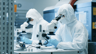
Cleanrooms maintain cleanliness by preventing particulates of human origin from entering the room and by capturing them with high-performance filters. In order to maintain the cleanliness of a cleanroom, it is first necessary to reduce the amount of dust, germs, sweat, hair, and other debris emitted by humans.

Depending on the required level of cleanliness, workers change into special white dustproof clothing and shoes, put on gloves, and wear caps to keep hair out. In addition, safety glasses and masks may be used. When entering the cleanroom, the workers are given an air shower to wash the dust from their bodies. 

2. Purification of Indoor Air

The air taken in through the intake ports in the cleanroom is circulated and purified of particulates and other contaminants by high-performance filters called HEPA filters installed in the air outlets. The cleanliness of the cleanroom can be monitored by a particle sensor.

Cleanrooms are also airtight, and are designed to prevent unnecessary particulates from entering from the outside by adjusting the air pressure in the room.

Types of Cleanrooms

Cleanrooms can be broadly classified into two types: those used for precision equipment manufacturing, or those used for food production and medical or life science research. Cleanrooms used in medical and life science research institutions are specifically referred to as bio-cleanrooms or sterile rooms.

In industrial applications, dust in the air is expected to be eliminated, but in bioclean rooms, in addition to this, it is necessary to prevent contamination by microorganisms such as bacteria and viruses.

Other Information on Cleanrooms

1. Cleanroom Standards

Cleanrooms are further classified according to the number of particles per unit volume of air. In Japan, three types of standards are used for classifying clean rooms: the U.S. Federal Air Ductility Standard (FED), the ISO standard.

U.S. Federal Clean Air Standard FED209E
The U.S. Federal Standard for Air Quality, FED209E, was discontinued in 2001 and replaced by the ISO standard 14644-1, but the industry still uses the widely used FED in many cases.

FED
The FED is classified into six categories, from Class 1 to Class 100,000, with the class number representing the number of particulates per unit volume. In other words, the smaller the class number equates to a higher level of cleanliness.

ISO Standards

ISO standards are further subdivided into nine (ISO) classes, from Class 1 to Class 9, in addition to the six classes corresponding to the FED standards.

2. Cleanroom Systems

173_Cleanrooms_クリーンルーム-1.png

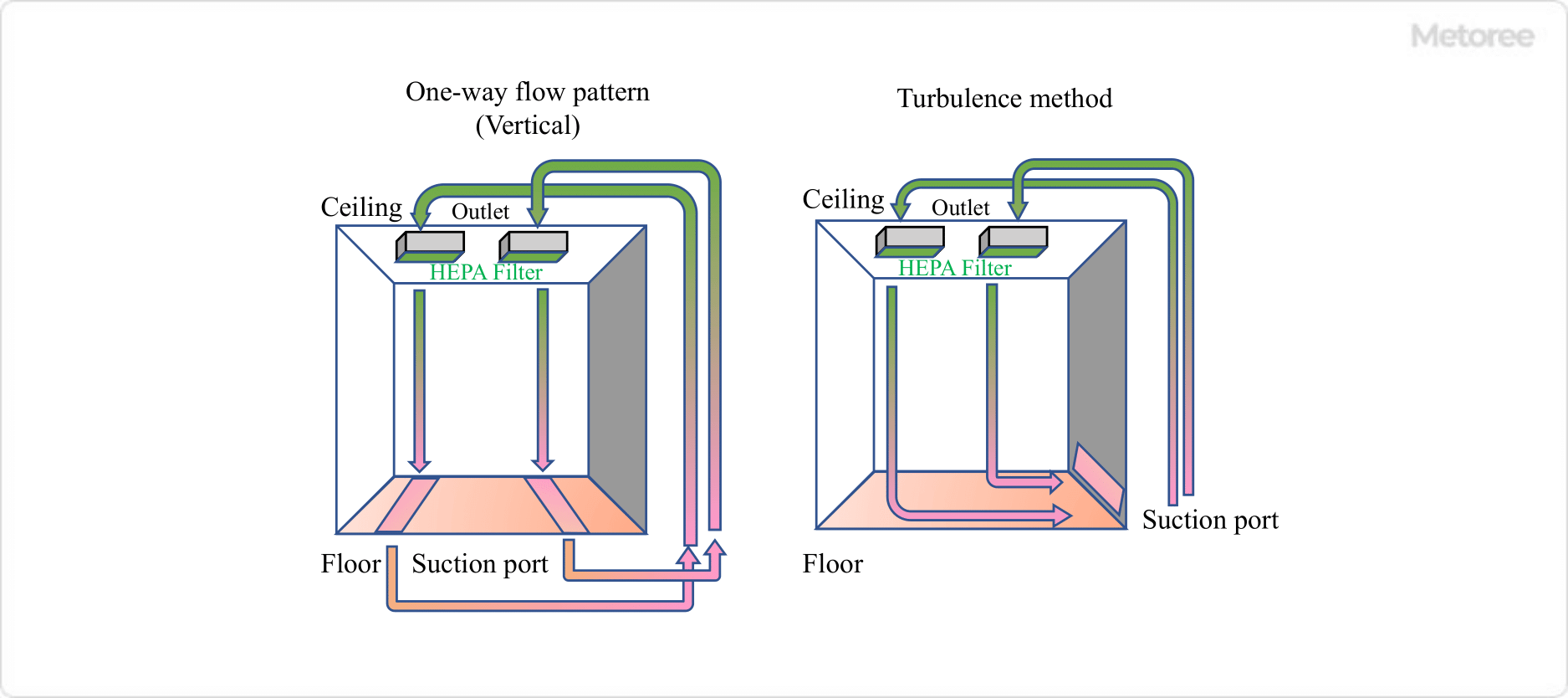
Figure 1. Clean room system

Cleanrooms can be classified into two types according to the way in which air is circulated, i.e., the way in which airflow is created: the unidirectional flow method and the turbulent flow method.

Unidirectional Flow Method
In the one-directional flow method, the air outlets and inlets are installed facing each other to create a uniform air flow. If a ceiling vent and floor inlet are installed, a uniform airflow can be created vertically. If a vent is installed on one wall and an inlet on the opposite wall, a uniform airflow can be created horizontally.

The unidirectional flow method can maintain a high level of cleanliness because the airflow is constantly circulating.

Turbulent Flow Method
The turbulent airflow method is a method in which the air outlets are installed on the ceiling and the intake ports are installed on the wall. Because there are areas where airflow stagnates, the cleanliness is inferior to that of the unidirectional flow method, but the advantage is that it can be introduced and operated at a relatively low cost.
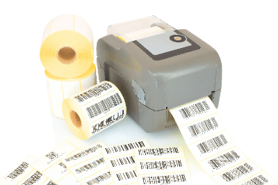
カテゴリー
category_usa

Fiber Optic Cable

What Is a Fiber Optic Cable?

Fiber Optic Cables

Fiber optic cables are cables used in fiber optic communications that transmit information using optical signals.

Multiple fibers called optical fibers are bundled together and coated. Fiber optic cables are becoming more and more important as the modern internet is shifting from telephone line communications to fiber optic communications.

Optical fiber is a highly transparent fiber made of high-purity glass fiber, which can propagate optical signals over long distances with virtually no attenuation. As a result, high-speed communication over longer distances is possible than over telephone lines.

Uses of Fiber Optic Cables

Major uses of fiber optic cables include various types of measuring instruments, illumination and other lighting, and medical and industrial fiberscopes. Fiber optic cables are used for a variety of applications other than optical lines for the Internet.

Fiberscopes are devices used to observe the inside of devices and human bodies that are difficult to access. Medical endoscopes are also a type of fiberscope, which enables real-time confirmation of affected areas based on optical information propagated through optical fibers.

Principle of Fiber Optic Cables

Fiber optic cables are made up of two types of glass: the core in the center and the cladding around the core. The core is made of glass with a high refractive index and the cladding is made of glass with a slightly lower refractive index. This causes the optical signals in the cable to be totally reflected at the boundary between the core and cladding, allowing optical signals to propagate far without attenuation.

Types of Fiber Optic Cable

Fiber optic cables are classified into two types according to the diameter of the core: single-mode fiber and multimode fiber.

1. Single-Mode Fiber

Single-mode fiber is an optical fiber with a small core diameter (about 10 μm). It transmits only light that is totally reflected at a certain angle. Since the arrival speed of light is constant, large-capacity communications can be carried stably over long distances. 

2. Multimode Fiber

An optical fiber with a large core diameter (about 50 μm) that simultaneously transmits multiple beams of light at different angles of total reflection. Since the arrival speed of each light differs, it is not suitable for long distances and is mainly used for short-distance medium- and small-volume communications.

Optical Fiber Cable Connection Methods

There are two main types of optical fiber splicing methods: fusion splicing and connector splicing. Since each method has different characteristics, select the splicing method that best suits the application.

1. Fusion Splicing Method

The tips of optical fibers are heated and melted to bond the tips of two optical fibers. The fusion splicing method requires less space for splicing because the signal attenuation at the splicing point is small. Since the splicing part is vulnerable to shocks and easily broken, a fiber protective sleeve is covered over the core wire reinforcement and heat-treated.

There are two types of splicing methods:

  • The core alignment method, in which the core center axis is aligned under a microscope and spliced.
  • The fixed V-groove alignment method, in which multi-fiber cores are aligned in a fixed V-groove and fused by surface tension during melting.

2. Connector Method

This is a method of splicing using a dedicated connector. While the fusion splicing method cannot be removed once spliced, the connector method can be repeatedly connected and disconnected. This method is used in places where switching points are required, such as for optical service operation and maintenance. Another advantage is that the connector tip shape can be freely selected, allowing direct connection to equipment.

Other Information on Fiber Optic Cables

Disconnection of Fiber Optic Cables

 There is a risk of cable breakage due to the following causes: 

1. External shock
This is the simplest case in which a fiber optic cable is subjected to a shock and breaks. Fiber optic cables, which are made of thin glass material, may be damaged by a shock. Care should be taken to avoid wiring in areas where there is a lot of pedestrian traffic. 

2. Disaster-induced utility pole damage
In some cases, fiber-optic cables may break due to shocks to utility poles where optical lines are connected. The fiber optic cable connected to the pole is damaged when the pole is impacted by an earthquake or accident. 

3. Damage by animals
In some cases, the cable may be broken due to animals chewing on it. If you have a pet, you should avoid wiring over the pet’s conductor or take measures to prevent pets from passing through.

Price of Optical Cable

The price of optical cables varies depending on the type and the shape of the connector. Single-mode fiber is a bit more expensive than multimode fiber.

SC connectors are the cheapest, followed by LC connectors and FC connectors, in that order. If connectors are not needed, cables without connectors can be purchased, in which case the cost will be the lowest.

Also, optical cables supporting 10 Gbit with faster transmission speeds are a bit more expensive. Other highly durable cables for outdoor use will be even more expensive.

Generally, volume discounts are available, and some companies can lower the price by purchasing cables in large quantities.

カテゴリー
category_usa

Scanning Probe Microscope

What Is a Scanning Probe Microscope?

A scanning probe microscope (SPM) is a microscope that uses a needle-sharp probe to observe surface irregularities on the nanometer scale.

It is often used in a high vacuum to clean the sample surface, but can also be used in air. Recently, microscopes that can be used in liquid have also been developed.

There are various types of scanning probe microscopes, including scanning tunneling microscopes (STM) and atomic force microscopes (AFM). The latter of which was awarded the Nobel Prize in Physics in 1986 for its ability to capture individual atoms and for its significant contribution to the advancement of nanostructure science and technology.

Uses of the Scanning Probe Microscopes

Scanning probe microscopes are used to observe the surface conditions and measure the roughness of semiconductors, glass, liquid crystals, and other materials because they can observe surfaces at the nanometer level, which is extremely fine.

Specific targets for observation include the atomic arrangement of silicon single crystals and phenyl groups in organic compounds. It can also be used to observe and manipulate DNA in biological samples such as microorganisms, bacteria, and biomembranes.

The scanning probe microscopes are new microscopes developed in the 1980s, but its applications are expanding rapidly, with remarkable advances in atomic-level observation technology and the development of models that can measure friction, viscoelasticity, and surface potential. Measurement in liquids is also used in fields such as electrochemistry and biochemistry, enabling measurement of conditions closer to real environments.

Principle of Scanning Probe Microscopes

This section describes the principles of AFM and STM, two of the most commonly used scanning probe microscopes. The tip of a fine needle-like probe scans the surface of a sample to acquire image and position information. The probe is thin and scans at the atomic level, so it is not suitable for measuring samples with too much unevenness.

1. Scanning Tunneling Microscope (STM)

STM takes advantage of the fact that the strength of the tunneling current emitted from the tip of a metal probe toward the sample depends sensitively on the thickness of the insulator, the vacuum, and in between. It can accurately measure the local height of the sample surface with a high resolution (the shortest distance between two neighboring points) that allows us to resolve individual atoms on the surface of the material. The probe also allows the observation of atomically scaled unevenness patterns as the probe scans the sample surface.

The probe is made of tungsten or platinum with a pointed tip. When the probe and sample are brought close enough that their electron clouds overlap and a small bias voltage (a voltage used to define the DC operating point for small-signal amplification of an amplifier) is applied, a tunneling current flows due to the tunneling effect.

In STM, the tunneling current is kept constant by moving the metal probe horizontally (X, Y) across the sample surface and by feedback control of the distance between the probe and the sample (Z). Usually, the vertical movement is performed with a piezoelectric element that can control the distance with a precision smaller than the size of a single atom, and the interaction between single atoms is detected. Thus, STM has atomic resolution in three dimensions. A piezoelectric element is a passive device that utilizes the piezoelectric effect, a phenomenon in which a voltage is generated when pressure is applied.

2. Atomic Force Microscopy (AFM)

AFM measures the difference in microscopic atomic forces (weak cohesive forces between atoms that are not chemically bonded) between the probe and the sample surface and observes the surface by scanning it. A wide variety of models have been developed to measure frictional force, viscoelasticity, dielectric constant, and surface potential by applying AFM technology.

A probe attached to the end of a cantilever (cantilever) is brought into contact with the surface of a sample by a very small force. The distance (Z) between the probe and the sample is feedback-controlled to maintain a constant force (deflection) on the cantilever while scanning horizontally (X, Y) to obtain an image of the surface topography.

Other Information About Scanning Probe Microscopes

Types of probes

AFM and SPM, which are typical examples of scanning probe microscopes, both use probes, but they differ in type. Furthermore, there are many types of AFM alone, including materials and lengths, and it is important to select one that best suits the object to be measured.

In addition to the contact mode described in the principle, AFM also has a tapping mode, which is used to measure fragile organic samples and uses a dedicated probe. The probe is a consumable item and must be replaced by the user.

カテゴリー
category_usa

Image Processing System

What Is an Image Processing System?

An image processing system is a series of system configurations that process, synthesize, and read characteristics of 2D and 3D images and data.

Image processing systems have become an indispensable technology for automatic machines and industrial robots because they replace the human eye and enable a variety of judgments and measurements.

Uses of Image Processing Systems

Today, image processing is used in an extremely wide range of fields, including the following:

1. Medical Field

CT and MRI are the two most common types of image processing used in the medical field: CT is a two-dimensional (3D) extension of conventional X-ray images, allowing for the entire body to be observed; MRI uses a strong magnetic field and electromagnetic waves to allow diagnosis without the use of radiation. Both types of examinations use image processing technology to observe the inside of the body from various angles.

2. Industrial Field

In the industrial field, many image processing systems are used in manufacturing lines. They are used for recognition, pickup, and alignment of parts in the assembly process, piece counting, visual inspection, and dimensional inspection in the inspection process, sorting and packaging in the shipping process,. They are also used in a wide range of hazard monitoring, contributing greatly to process automation.

3. Transportation

Typical applications in the transportation field include automobile driver assistance and driving automation. By processing camera images not only from the front but also from the entire 360° angle, the system detects pedestrians, obstacles, and other vehicles, and alerts the driver or takes evasive action.

In addition to automobiles, the system is also used in railroad systems for equipment monitoring and security surveillance, and is useful for monitoring a wide area in a changing brightness environment such as outdoors and along railroad lines on behalf of humans.

4. Security Field

A typical example of use in the security field is facial recognition systems. In addition to its widespread use in smartphones, it is also useful for enhancing security when entering and exiting buildings.

Principle of Image Processing Systems

Image processing systems work as follows:

1. Image Input

Light distribution is converted into electrical signals, mainly using CCD sensors.

2. Smoothing

Smoothing, a type of preprocessing, is a process that gives a smooth out-of-focus gray scale change. Smoothing is also called an averaging filter because it calculates the average value of the pixels in the area covered by the filter and defines that value as the new pixel count. It is used as a spatial filter to smooth an image and remove noise. 

3. Feature Extraction

One of the feature images is a binary image. Binarization is the process of reducing an image from several levels of density to only two levels: white and black. An image with only one level of density, either white or black, is said to be a binary image.

One way to determine the nature of an image using tonal values is with a histogram. The number of pixels is taken on the horizontal axis and the frequency of pixels on the vertical axis, and the information is plotted on a graph. The histogram is then processed by dividing the number of shades on the horizontal axis of the histogram into two, with the pixel data being divided into 1 if the number of shades is greater than that, and 0 if the number is less.

4. Evaluation

Feature images obtained by feature extraction are evaluated according to the purpose.

Other Information on Image Processing Systems

1. Camera Selection for Image Processing Systems

Camera selection is very important for image processing. Cameras are used in image processing systems to acquire image data of the workpiece in the image input process.

At production sites, for example, a camera that functions as an eye is used to capture images of inspection objects such as circuit boards in order to inspect the flaws and conditions of products. However, different shooting conditions can cause variations in inspection accuracy.

In order to ensure that the shooting conditions are as identical as possible, the camera must be appropriately selected along with the lens, lighting, and other factors. Image processing systems can be broadly classified into the following two types.

Area Sensor Camera Method
This is the most commonly used imaging method and can obtain a two-dimensional image. The size of the image that can be acquired is determined by the camera.

Line Sensor Camera Method
This method continuously acquires one-dimensional images to obtain two-dimensional images. The camera or workpiece must be moving in a certain direction when acquiring images. This method is effective for capturing images of relatively large workpieces. It is necessary to select an appropriate camera after fully understanding the requirements.

2. Real-Time Processing in Image Processing Systems

Computational processing found in an image processing system, software, or hardware. Software processing is highly flexible because it can be changed to accommodate various changes in the program, but hardware processing is required in situations where real-time processing is required to avoid hazards.

For example, an around-view monitor used to avoid collisions when parking a car originally projects images in real time from above the car, where there is no camera. The image is generated in real time by synthesizing image data from onboard cameras using dedicated hardware, such as an ASIC.