Gouging Rod

What Is a Gouging Rod?

Gouging Rods
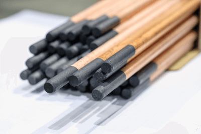
A gouging rod is a carbon rod for gouging using a welding machine.

The purpose of gouging is to remove defective areas that occur during welding. An arc is generated between the carbon gouging rod and the metal plate to melt the metal around the defective area, and at the same time, the molten metal is mechanically removed to groove the metal plate.

Note that arc refers to arc welding using the electrical discharge phenomenon. It refers to a welding method in which the base metal and gouging rod are melted by the high heat of the arc generated between the base metal and the gouging rod.

Uses of Gouging Rods

Gouging rods are used in the arc-air method. The arc-air method is a method of digging trenches by melting a metal base material with an arc and blowing the molten metal away with a high-speed air jet.

Major applications include steel frames, bridges, shipbuilding, and can manufacturing. It can be used for cutting the back of welds, cutting bevels, or defects in welds, or it can be used for cutting castings, such as the pouring of castings or the opening of a hot water tank, or for cutting nests.

Other applications include U-shaped beveling, cutting, and drilling of mild steel plates, and processing of cast iron and cast steel repair welding.

Principle of Gouging Rods

In air-arc gouging using a gouging rod, a gouging rod is placed between a torch and a base metal, and a DC or AC arc is generated between this electrode and the base metal to melt the material locally while blowing it away with air to dig a groove.

There is another method that does not use air, but uses an AC or DC welding machine and a welding rod with a special flux applied to the mild steel core wire. Beveling of stainless cast iron, mild steel, cast steel, and various alloy steels, removal of defects such as grooves and cracks, and drilling of holes can be easily performed by adjusting the current and the angle between the welding rod and base metal.

The angle of the welding rod to the base metal should be 10 to 30°. If the angle is smaller than this, the workability is better, but the welding rod wears out more rapidly. Conversely, if the angle is larger, deep penetration is possible, but the flow of molten metal is reduced.

Types of Gouging Rods

1. Gouging Rod for Direct Flow

DC gouging rods can be used in many ways, including beveling, cutting, drilling, and flaw removal on steel plates.

2. Alternating Current Gouging Rod

AC gouging rods are made of special high-grade raw materials to completely solve the arc difficulty inherent in AC. Outstanding arc safety improves work efficiency and economy.

3. DC Hollow Gouging Rod

DC hollow gouging rods are ideal for digging a smooth gouging trail. With a regular gouging rod, the depth of the gouging moat is dug sharply, but with a hollow, the current is not concentrated at the tip, making it easier to dig a shallow, U-shaped bottom.

Other Information About Gouging Rod

Gouging Methods

There are two methods of gouging using gouging rods:

1. Air Carbon Arc Gouging Method

The air carbon arc gouging method is a method of removing defects by melting the base metal by generating an arc between the gouging rod and the base metal. When the base metal is melted, air is injected along the gouging rod to remove the molten metal.

The air carbon arc gouging method is more efficient than conventional methods and can be used for stainless steel. Another advantage is that it has less impact on the base metal.

2. Plasma Arc Gouging Method

Plasma arc gouging method is a method using plasma cutting and transitional plasma arc. The high-density, high-temperature energy of the plasma arc causes little deformation after gouging and can be applied to any metal.

Another advantage is that the work can be automated and does not generate as much noise and dust as the air carbon arc gouging method. Therefore, the plasma arc gouging method is often used for gouging.

Exhaust Cleaner

What Is an Exhaust Cleaner?

Exhaust cleaners are air cleaning devices used at the exhaust ports of solenoid valves and cylinders in pneumatic systems.

Exhaust cleaners serve two purposes: first, they reduce the noise generated by the exhaust. The sound deadening performance is higher than that of a silencer, with an effect of 35 dB or more.

The second is to remove oil and dust from the compressed air exhausted from the pneumatic system. Installing an exhaust cleaner will help to collect these and properly discharge them. Installing an exhaust cleaner will provide a quiet and clean working environment.

Uses of Exhaust Cleaners

Exhaust cleaners are used to remove noise from the exhaust of a pneumatic system and mist oil and other particles in the exhaust. The pneumatic system contains three units: an “air filter,” a “regulator,” and a “lubricator,” which perform the following functions:

  • Removes impurities generated and mixed in pneumatic lines
  • Pressurization and pressure maintenance
  • Lubricant supply

These features ensure stable operation of the pneumatic system and prevent deterioration and breakdowns. Compressed air passing through the unit has the problem of generating “noise” and “contamination” during exhaust. Noise can be reduced by using silencers, but compressed air contaminated with dust and oil mist requires countermeasures.

If left unchecked, the problem can cause contamination and clogging of the discharge port, eventually leading to equipment failure. Furthermore, there is a risk of adverse effects on the human body, causing respiratory and internal diseases. Exhaust cleaners are installed as a countermeasure.

Exhaust cleaners can be installed to remove dust and mist oil from the exhaust in addition to exhaust noise.

Principle of Exhaust Cleaners

Exhaust cleaners purify exhaust and collect oil with a filtering material called an “element. This “element” also has a muffling effect.

1. How Oil Mist Is Generated

Actuators such as air cylinders are widely used in lubrication-free devices that can be used without lubrication by adhering the required amount of grease during assembly.

On the other hand, lubrication of cylinders may be done by mixing oil into compressed air using a lubricator. Then, oil is also mixed in the exhaust air, and oil mist is generated.

2. Purify the Discharged Compressed Air

This compressed air, which contains oil mist and dust, is purified by passing it through an exhaust cleaner. This is where the filtering material inside the exhaust cleaner, called the “element,” comes in.

The oil in the exhaust is filtered on the surface and inside the element, and further condensed and collected by falling down inside and on the surface of the element and accumulating in the oil case section.

3. Drain the Collected Oil

Collected oil is discharged from the drain port using a “drain cock” or “drain pipe” system. In a drain cock, oil is drained by opening the cock. Drain piping is a method for constantly draining oil by connecting oil reservoirs with piping. The oil is also passed through an element to muffle the sound.

How to Choose an Exhaust Cleaner

The size varies depending on the effective cross-sectional area and the maximum treatment flow rate, so selection is based on the nature of the use. The basic rule of thumb is to select an exhaust cleaner with a treatment capacity greater than the maximum required volume of compressed air exhausted from the solenoid valve.

When multiple solenoid valves are used in a centralized piping system, calculate the maximum required peak air volume, including the volume of the piping connected to the actuators and other equipment operating simultaneously. The equipment is then selected so that the value is less than or equal to the maximum process flow rate of the exhaust cleaner.

Note that using more than the maximum throughput of the exhaust cleaner may cause oil to be splashed around or damage the element.

Other Information on Exhaust Cleaners

Element Clogging

Exhaust cleaners have a smaller effective cross-sectional area and clog the element more quickly than regular silencers. As a guideline for detecting element clogging, measure the internal pressure during exhaust.

If the internal pressure rises above a certain level, it is a sign that the element is not venting well and is considered to be clogged. Normally, replace the element before it reaches 0.1 Mpa.

カテゴリー
category_usa

Urea Grease

What Is Urea Grease?

Urea Greases

Urea grease is a grease that contains two or more urea bonds, which are difficult to decompose, and a thickening agent that ensures scientific stability.

The thickening agent is mixed with the liquid to make it semi-solid. Grease is generally used for machines that rotate at relatively low speeds, bearings that are subject to high loads, and sliding surfaces where metals slide against each other to reduce friction and the burden on equipment.

It is classified into various types depending on the thickening agent and base oil used, and the characteristics of the thickening agent in particular almost determine the characteristics of the grease. The characteristics of urea grease, which reflect the properties of urea, are higher heat resistance and water resistance than other greases.

In addition, urea grease has a unique consistency. Therefore, it can protect machinery for a longer period compared to other greases using thickening agents, which have the same hardness.

Uses of Urea Greases

Urea grease has excellent heat and water resistance. For this reason, it is often used in bearings and sliding parts of equipment that are driven under high temperature conditions.

For example, in metal rolling mills, machines must be operated under high loads and high temperatures while spraying cooling water. Under these special conditions, urea grease is suitable because of its excellent heat and water resistance.

Urea grease is also used in general household products. For example, it is used inside reels attached to fishing rods. By using urea grease with high water resistance, it is possible to protect the internal parts from seawater. The unique consistency of urea grease protects the precision gears inside the reel.

Principle of Urea Greases

Urea, which is used as a thickening agent in urea grease, is scientifically stable and has two or more urea bonds that are not easily decomposed. Ureas are further classified according to the number of urea groups: 2 is diurea, 3 is triurea, and 4 is tetraurea. Of these, diurea has superior performance as a grease. For this reason, diurea is widely used in urea-based greases.

Characteristics of Urea Grease

1. Chemical Characteristics of Urea Grease

Diureas are further subdivided according to the structure of the two ends of the thickener molecule. The classifications are aromatic diurea, aliphatic diurea, and alicyclic diurea. Among these, aromatic diurea has the highest grease performance, with excellent water resistance and shear stability. Other aliphatic diurea greases are fluid and soften in shear when shear force is applied.

When the flow stops and the shear elasticity is lost, the grease returns to its original hardness. It is suitable for use in centralized lubrication (a method in which grease is supplied to multiple locations by a single grease pump). Another advantage is that softening during shear reduces torque and noise when used in bearings.

In addition to the characteristics of the structure at the molecular level, the performance of the base oil (base oil) also has an effect on the grease. There are many types of metal soap-based greases, such as calcium soap, lithium soap, molybdenum disulfide, and lithium complex. On the other hand, non-soap-based greases exist, such as urea, of which urea grease is a typical example.

2. Physical Characteristics of Urea Grease

In general, the hardness of grease varies depending on the amount and type of thickener blended, and is indicated by “viscosity”. The “mixing consistency” value is generally used as the “degree of hardness”. Grease hardness is classified as No. 000, No. 00, No. 0, No. 1, No. 2, No. 3, No. 4, No. 5, and No. 6.

Grease with a degree of admixture modulus in the range of 445 to 475 is soft grease in a semi-fluid state and falls under No. 000. Grease with a miscible consistency ranging from 85 to 115 is labeled No. 6 and is very hard grease. Many urea grease products have a degree of mixing consistency of about No. 2 and are classified as normal hardness grease. Although the hardness is normal, the use of urea-based thickening agent makes this grease not only rustproof, lubricating, and wear-resistant but also highly heat- and water-resistant and long-lasting.

Other Information About Urea Grease

1. Types of Grease Thickeners

Tightener makes the base oil, which constitutes the grease semi-solid. By mixing the base oil with the thickener, the thickener is incorporated into the base oil and becomes semi-solid.

There are two major types of thickeners: metallic soap type and non-soap type. There are many types of metallic soap-based greases, such as calcium soap, lithium soap, aluminum complex, and lithium complex. On the other hand, non-soap-based greases include bentonite, PTFE, and urea, with urea grease being a typical product.

2. Disadvantages of Urea Grease and Measures to Deal With Them

Urea grease has many advantages over lithium-based grease, but it also has disadvantages. Some types of urea grease harden when used in high-temperature environments. This phenomenon occurs because the thickener molecules polymerize under high temperature.

Therefore, regular use near the heat resistant temperature may cause performance degradation due to hardening, so care should be taken. Before using this grease, please check the grease brand name thoroughly in the manufacturer’s catalog before applying it to the machine. There are also urea greases that soften and harden to a greater degree when sheared.

There is no problem if the selection or machine design is intentionally made to take advantage of these characteristics, but since unintended changes may cause malfunctions in the machine used, sufficient confirmation is required prior to use.

カテゴリー
category_usa

Sfp Module

What Is an SFP Module?

SFP Module
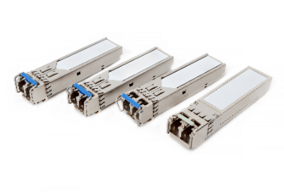
SFP (small form-factor pluggable) modules are optical transceivers that convert electrical signals into optical signals.

They are mainly used in data communication applications to connect network devices. SFP modules can be used with UTP cables, which have a transmission distance limit of 100 meters, and can be extended beyond this limit.

It is specified by the multi-source agreement (MSA) and supports gigabit ethernet, SONET and other communication standards.

Uses of SFP Modules

SFP modules are used to convert electrical signals into optical signals; with SFP modules, transmission media such as multi- and single-mode fiber, twisted pair cables, and coaxial cables can be connected with the required distance length and transmission speed.

They are also used in “storage interface cards” called HBAs or fibre channel storage switches, and support a wide range of speeds from 2 to 8G. Compact SFP Modules offer a variety of fiber-optic connections.

These low-cost modules are useful for increasing the flexibility of devices, such as switching hubs, routers, and firewalls. SFP Modules that provide fiber-optic connectivity are also characterized by their resistance to noise. Therefore, they are used to prevent communication problems in environments with many noise sources.

Principle of SFP Modules

The following components make up the SFP module:

  • CDR (Clock and Data Recovery)
  • TIA/LA (Trans-impedance Amplifier/Limiting Amplifier)
  • MCU (Microcontroller Unit)
  • LDD (Laser Diode Driver)
  • TOSA (Transmitter Optical Subassembly)
  • ROSA (Receiver Optical Subassembly)

The TOSA converts the electrical signal into an optical signal for transmission, and the ROSA converts the optical signal into an electrical signal for reception. The CDR matches the signal on the receiving side with the signal on the transmitting side. The TIA processes the current signal converted by the ROSA into a voltage signal of a specific amplitude. The LA processes this output amplitude into a voltage signal of equal amplitude.

The LDD converts the clock signal output from the CDR into the corresponding modulation signal, which drives the laser to transmit an optical signal. The MCU is responsible for monitoring the operating status of the optical module and maintaining optical communications. Specifically, the MCU monitors parameters related to software operation, temperature, voltage, current, receiving power, and transmitting power in real time to determine the operating state of the optical module.

Types of SFP Modules

There are two types of SFP: SFP Fiber Module and SFP Copper Module.

1. SFP Fiber Module

Most SFP fiber modules are either CWDM (Coarse Wavelength Division Multiplexing) SFP or DWDM (Dense Wavelength Division Multiplexing) SFP, with CWDM using wide channel spacing and a maximum transmission distance of 120 km and DWDM using high-density channel spacing and a maximum transmission distance of 200 km.

2. SFP Copper Module

There are three types of SFP Copper Modules: 1000BASE-T, 10/100BASE-T, and 10/100/1000BASE-T. The operating distance for 1000BASE-T is 100 m over twisted pair cable; for 10/100BASE-T and 10/100/1000BASE-T, it is 100 m over copper twisted pair cable. It is important to select the SFP Module according to the required operating distance.

Other Information on SFP Modules

Cautions for SFP Modules

When using SFP modules, the most important thing to consider is compatibility.

You must be very sure that the SFP module is compatible with the device to which it will be connected.

The operating environment and maintenance methods are important to prolong the service life. Avoid damaging end-faces, plugging in lightly, and using in proper humidity.

カテゴリー
category_usa

Burnishing Drill

What Is a Burnishing Drill?

Burnishing Drills
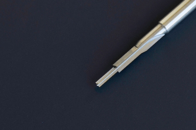
A burnishing drill is a tool that can perform both drilling and burnishing at the same time.

Burnishing means polishing the surface and is widely used for drilling holes that require high surface roughness. A reamer (or burnishing reamer) is a tool with similar performance.

While reamers can finish the surface of an already drilled hole, burnishing drills have a cutting edge called a “chisel” with an angled tip that allows finishing at the same time the hole is drilled. Because finishing work after drilling generally takes time and tends to leave surface defects, simultaneous drilling with a burnishing drill is both efficient and precise.

However, when using burnishing drills, incorrect cutting edge angle or rotational speed may result in chipping or damage to the cutting edge during drilling. It is also important to note that burnishing drills have a higher load than reamers and must be properly cooled.

Uses of Burnishing Drills

Burnishing drills are suitable for high-precision drilling because they do not require surface finishing after drilling. For example, burnishing drills are widely used in the machining of automobile and aircraft engine parts, and are also indispensable in the machining of dies and molds.

Furthermore, many burnishing drills have a multi-stage shape, making them suitable for machining workpieces with multiple hole diameters. They can also be applied to the machining of soft materials such as resins and aluminum alloys.

Since drilling and burnishing can be performed simultaneously, machining time is reduced and the number of tools is reduced, making this tool applicable to a variety of manufacturing sites. Burnishing drill blades are basically straight, but some are equipped with a spike-shaped blade to accommodate high-speed feed and deep holes. Another feature is that there are a wide variety of types to suit different applications, such as those with oil holes and those that can handle small holes of 1 mm or less.

Principle of Burnishing Drills

Burnishing drills are machining tools that smoothly connect the cutting surface to the hole wall by means of a margin, called a burnishing margin, to achieve high-precision machining. The disadvantage is that the chisel and clearance grooves reduce rigidity, but they still offer advantages such as reduced cycle time and the elimination of the need for drilling for the downhole. This makes it an ideal tool for machining workpieces, where productivity is important.

Burnishing drills also have the advantage of machining more accurately in a shorter time than when using a reamer for drilling. When drilling, burnishing drills have a spherical tip, which distributes the cutting force evenly and provides a uniform finish on the workpiece surface. Therefore, burnishing drills provide a smoother surface finish than reamers.

Reamers are used for deep holes, but when using burnishing drills, it is recommended to use oil-hole compatible ones.

Types of Burnishing Drills

There are four types of burnishing drills: straight blade burnishing drills, gauge blade burnishing drills, multi-blade burnishing drills, and burnishing drills with oil holes.

1. Straight Blade Burnishing Drill

Straight blade burnishing drills are a type of drill with a straight cutting edge. It is used for simple hole drilling. Because of its straight shape, it has the disadvantage that the larger the diameter, the lower the machining accuracy.

2. Gauge-Blade Burnishing Drill

Gauge-blade burnishing drills are a type of drill with a conical cutting edge. It is used for drilling the bottom of holes because it can cleanly drill the bottom of holes. Also, when used in combination with a step drill, the range of hole diameters can be expanded.

3. Multi-Flute Burnishing Drill

A multi-blade burnishing drill is a type of drill with multiple blades. They are suited for mass production because they provide good chip removal and reduce machining time. However, there is a disadvantage in that the large number of blades results in a narrower distance between the cutting edges, which reduces the strength of the cutting edges.

4. Burnishing Drill With Oil Hole

Burnishing drills with an oil hole are a type of drill with a hole in the center of the cutting edge to supply coolant oil. Chips can be removed by coolant water pressure, making this type of drill suitable for high-speed and mass production.

カテゴリー
category_usa

Bug Filter

What Is a Bug Filter?

Bag FiltersA bug filter is a type of dust collection device that uses a woven or non-woven filter cloth to collect very fine particles and dust suspended in gases and purify the gas or gases to be treated.

It is called a bug filter because the filter cloth is made into a cylindrical shape and its bag is suspended at the point where the treated gas flows in.

Although electrostatic precipitators that use electricity are also available, bug filters have the advantage of being inexpensive and easy to install compared to such precipitators.

Uses of Bug Filters

Bug filters are used at manufacturing and processing sites where soot and smoke containing large amounts of particulate matter and dust that are harmful to the human body and the environment are generated.

Typical examples are the large incinerators installed in steel plants to process waste materials.

Air purification using bug filters is also very important to keep the air clean in confined spaces or sites where a lot of dust is generated, and to control dust explosions and other hazards, thereby ensuring safe operations.

Bug Filter Material

The filter cloth used in bug filters is usually made of materials ranging from cotton to high polymer synthetic resins such as polyester, nylon, polypropylene, acrylic, Teflon, and glass fiber.

Ceramic ones are also used, depending on the temperature of the gas to be processed.

The material of the bug filter is determined based on the operating temperature, the nature of the gas, the properties of the particles, durability, and price.

For example, polyester is inexpensive but susceptible to high temperatures and alkalis. Polyimide is resistant to solvents, but weak against acids and alkalis; PTFE has good heat resistance and chemical resistance, but is very expensive. Glass fiber has excellent heat resistance and chemical resistance, but is expensive and has poor durability.

While bug filters are simple to install, the selection of filter cloth has a direct impact on running costs, because filter cloth replacement is a prerequisite. On the other hand, if the size is the same, it is easy to change the material, and the material can be changed according to the site conditions.

Principle of Bug Filters

Bug filters clean gas by trapping fine particles and dust in the gas as it passes through the filter cloth.

The bag filter has an extremely high particulate removal rate of approximately 99% and is capable of collecting even very small particles of 0.01 micrometer or less.

Although the collection capacity is very high, after a certain period of use, the pressure drop increases due to the accumulation of fine particles on the surface of the filter cloth, and the collection capacity of the bug filter declines.

Therefore, when the pressure loss reaches a set value, the accumulated particles must be swept off the filter cloth.

There are two main methods for this: the mechanical method and the pulse-jet method, in which compressed air is fed to the filter and the particles are swept off.

In addition, the method of injecting air from the opposite direction of the filtration direction is used to clean the glass fiber bug filters used in cement and steel smelting plants.

Bug Filter Pay-Off Method

Bug filters with large pressure losses need to be cleaned of accumulated particles, and mechanical vibration, reverse pressure, and pulse jets are available.

Mechanical vibration applies vibration to the bug filter, while counter-pressure removes accumulated particulate matter by blowing airflow in the opposite direction from that used for dust collection. The back-pressure method is used to clean glass-fiber bug filters used in cement and steel smelting plants.

However, mechanical vibration and back pressure require the airflow to be cut off when removing the particles, and dust collection must be interrupted. For this reason, the dust collector must be divided into multiple chambers to enable continuous operation.

In contrast, as shown in the figure below, the pulse-jet method, in which only a portion of the bugs are momentarily removed by applying a reverse jet, does not require interruption of dust collection, so continuous operation is possible without using a multi-chamber structure.

Bug Filter Trouble Cases

The basic structure of a bug filter is simpler than that of other dust collectors, allowing for space-saving installation and easy maintenance. Moreover, by appropriately selecting the material and size of the filter cloth, the fabric filter can demonstrate high dust collection performance in various environments. Because of these features, bug filters are widely used in various fields. However, this advantage is sometimes closely related to the cause of various problems.

The most common trouble is the dropping or breaking of the filter cloth. This is caused by localized concentration of gas containing particles and changes in flow velocity due to load fluctuations that cause the filter cloth to sway and contact adjacent filter cloths or casings. This can be solved by adding a rectifying plate, such as perforated metal, to regulate the gas flow. The number of filter cloths installed may be reduced and the density of the filter cloths may be lowered in areas where contact is possible, but only as a stopgap measure, since this will reduce dust collection efficiency.

The most serious problems are ignition and explosion. In general, most incinerator dust collection systems use bug filters. In incinerator bug filters, the target of dust collection is fine carbon, and because the system is often under negative pressure, outside air may be drawn in through gaps in the casing, creating the conditions for ignition. In addition, if the fine powder stays in the system due to clogging of the filter cloth, etc., the risk of dust explosion increases.

Although simple and easy to install, this equipment is also very sensitive. In order to prevent these problems, it is important to select an appropriate bug filter and perform regular maintenance.

カテゴリー
category_usa

Biomass Plastic

What Is a Biomass Plastic?

Biomass PlasticsA biomass plastic is a polymer material chemically or biologically synthesized from renewable biomass resources.

Although not necessarily biodegradable, they are known as environmentally friendly plastics due to their carbon neutrality. Since there are various raw materials, chemical structures, manufacturing methods, and functions, it is important to understand the characteristics of each material before using the appropriate one.

Uses of Biomass Plastics

Biomass plastics are used in a variety of fields as environmental measures are strengthened.

Specific uses of are as follows:

  • Non-food containers and packaging
  • Clothing fiber
  • Electrical and Information Equipment
  • OA equipment
  • Automobiles
  • Eco-friendly educational equipment
  • Cushions
  • Artificial grass (lawn)
  • Heat-resistant tableware containers

Principle of Biomass Plastics

Biomass plastic is a polymeric material chemically or biologically synthesized from renewable biomass resources. In other words, the raw material of biomass plastic is plant material that grows through photosynthesis using carbon dioxide.

Therefore, even if biomass plastics are incinerated and emit carbon dioxide, the total amount of carbon dioxide absorbed during growth and the total amount of carbon dioxide emitted during incineration is plus or minus zero, making them highly carbon neutral. Biomass plastics can be biodegradable or non-biodegradable.

Attempts are underway to make them biodegradable and return them to the soil to achieve a cycle in which plants are grown as raw materials. Thus, plant-derived raw materials for biomass plastics can be cultivated, and there is no concern about depletion compared to petroleum-derived raw materials.

Types of Biomass Plastics

There are three main types of biomass plastics. The most common of these are made from biomass resources, including inedible parts such as sugar cane and corn.

1. Biodegradable Biomass Plastic

Biodegradable biomass plastics are plastics made from biomass resources and are biodegradable. Typical examples are polylactic acid and polyhydroxyalkanoate (PHA). Of the many biodegradable plastics, polylactic acid (PLA) is the most commercialized. However, its limited popularity is due to its difficulty in molding, high price, and low strength.

2. Non-Biodegradable Biomass Plastics

Non-biodegradable biomass plastics are plastics whose raw materials are biomass resources but are not biodegradable. Typical examples are biopolyethylene and biopolyamide. They are not biodegradable, but they can achieve carbon neutrality. Although they are easier to handle than biodegradable plastics, their use is limited due to their higher price compared to general-purpose plastics.

3. Partially Biomass-Based Plastics

Partially biomass feedstock plastics are plastics produced using biomass feedstock as part of the raw material. Examples include polypropylene terephthalate (PPT), which is made by fermenting propylene glycol, one of the raw materials. Copolymers of polylactic acid and cellulose acetate also belong to this category.

Other Information on Biomass Plastics

1. Relationship With Biodegradable Plastics and Bioplastics

The difference between biomass plastics and biodegradable plastics is that biomass plastics are defined by their raw materials, while biodegradable plastics are defined by their function.

Biomass plastics, as we have mentioned, are polymeric materials chemically or biologically synthesized from renewable biomass resources as raw materials. Some biomass raw materials are biodegradable and some are not.

Biodegradable plastics, on the other hand, are plastics that are degraded by the action of microorganisms in the environment, and the raw materials are not necessarily of biological origin. For example, polybutylene adipate terephthalate (PBAT) is made from petroleum, which is derived from fossil resources, and sugarcane, which is derived from biomass.

Note that biodegradable plastics are used in plastic shopping bags, product packaging, drainage nets, computer parts, sandbags, fishing line, and agricultural mulch sheets. These are collectively called “bioplastics.”

2. Environment Surrounding Biomass Plastics

Global efforts to address environmental issues, particularly global warming, began with the Kyoto Protocol enacted in 1997. Global warming is believed to be caused by carbon dioxide and other greenhouse gases, and an international framework was established to curb their emissions. The Kyoto Protocol was limited to developed countries, but the Paris Agreement of 2013 includes developing countries.

Against this backdrop, many countries are working to reduce their carbon dioxide emissions, and one such effort is the conversion to biomass plastic. However, biomass plastics may cause the same problems as general-purpose plastics when they are disposed of, since few biomass plastics are made of 100% biomass materials. Besides, technological innovations as well as legislation are needed.

3. Problems With Biomass Plastics

Like regular plastics, biomass plastics have a microplastic problem. Many of the biomass plastics in use today are only partially biodegradable, and the remaining plastic fragments are crushed by the external environment, but they are not decomposed.

The remaining plastic fragments are crushed by the external environment, but they do not decompose. The final result is microplastics ranging in size from several micrometers to several tens of micrometers, which accumulate in animal bodies and are thought to have adverse effects on ecosystems and the human body through the food chain process.

カテゴリー
category_usa

Draft Chamber

What Is a Draft Chamber?

Draft ChambersA draft chamber is a type of local exhaust ventilation system used when handling hazardous substances that may affect the human body in chemical or biological experiments.

There are two main types of local exhaust ventilation systems: enclosed types, which cover the hazardous materials, and external types, which are open and have a hood placed next to the hazardous materials. Draft chambers are classified as enclosed local exhaust ventilators.

Among the enclosed types, there are four types: cover type, glove box type, draft chamber type, and building booth type.

The draft chamber type is characterized by a wide working table and easy operation through the large up-and-down (or left-and-right) sliding door that opens widely in front.

Uses of Draft Chambers

Businesses will be obligated to install draft chambers (or appropriate local exhaust ventilation) to protect the health and safety of workers.

Place the hazardous material in the draft chamber, and the operator should open the front sliding door slightly and work only with hands inside.

Never put your head inside the draft chamber at this time. Correct use of the draft chamber will not only prevent inhalation of vaporized or dispersed hazardous substances, but will also protect the safety of the operator in the event of an explosion.

Principle of Draft Chambers

Draft chambers do more than simply provide ventilation. The air that passes through the exhaust duct goes through a scrubber, which removes harmful substances, and is then exhausted outdoors.

Conventional constant-air-volume draft chambers exhaust a fixed amount of air regardless of whether the door is opened or closed. Therefore, without proper air supply, the balance between exhaust air and air supply will be upset, and the room in which the draft chamber is operating will not be able to maintain a negative pressure.

In addition, the constant air volume system exhausts a large amount of conditioned air to the outside, which has been considered a problem from the standpoint of energy conservation.

The variable air volume (VAV) system compensates for these shortcomings.

The variable air volume system automatically calculates the necessary exhaust air volume according to the degree to which the door is opened and closed, thereby reducing the wasteful exhaust of conditioned air.

Role of the Scrubber

Since the air in the draft contains volatilized solvents, reagents, and fine particles, it cannot be discharged directly into the standby area. Therefore, it is passed through a facility called a scrubber to trap harmful substances contained in the exhaust gas. Scrubbers are classified into dry and wet types depending on the trapping method.

  • Dry Scrubber
    Activated carbon and non-woven filters are installed on the exhaust gas path to collect dust and volatile organic solvents. By changing the type of filter, the system can handle a variety of gases.
  • Wet Scrubber
    Alkaline cleaning water is sprayed from a shower nozzle to dissolve and neutralize water-soluble gases. The ability to neutralize acidic vapors is an advantage not found in the dry type, but a disadvantage is the inability to collect non-water soluble vapors.

In addition, periodic voluntary inspections of the draft should also check for clogged or damaged scrubbers. During the inspections, protective equipment should be worn on the assumption that the filters and cleaning water contain hazardous substances.

Simple Draft Chamber

There are also simple draft chambers that can be placed on a tabletop. The transparent box-shaped body is equipped with an air blower and exhaust duct hose, and some models are also equipped with a filter for exhaust gas treatment. When in use, it is placed on a horizontal table, and the exhaust hose is connected to a local exhaust system to blow air.

It can be used as an alternative when a draft chamber cannot be installed, but since it is only a simple device, the following points should be noted.

  • Due to the small working space, the reagent bottles and beakers may be knocked over by hands during operation, resulting in splashing of the contents. Care should be taken to keep only the minimum amount of reagents in the box.
  • Gas or vapor may remain in the exhaust duct hose and may be blown out and aspirated when cleaning up. Local exhaust air should be kept running for a while after use to fully displace the air in the hose.
  • Exhaust filters are also simple and may not be able to handle large amounts of gas. Exhaust should be treated after passing through a scrubber, or restrictions should be set so that only small amounts of reagents are handled.

Other Draft Chamber Information

1. Mandatory Self-Inspection of Draft Chambers

Business operators who install draft chambers must conduct a voluntary periodic inspection once every year or less. 

The contents of the inspection include:

  • Whether and to what extent hoods, ducts, and fans are worn, corroded, dented, or otherwise damaged.
  • Dust accumulation in ducts and exhaust fans
  • Looseness at duct connections
  • Working condition of the belt connecting the electric motor to the fan
  • Intake and exhaust capacity

Other items necessary to maintain performance are listed below. Employers are required to conduct voluntary inspections to satisfy the above and record the results on an inspection sheet. In addition, this inspection sheet must be kept for three years, so please keep this in mind when introducing draft chambers.

If an abnormality occurs, the manufacturer should be consulted to finalize a countermeasure policy. If repairs are necessary, the results should be preserved as well.

2. Anemometer for Draft Chamber Inspection

One of the inspection items is to check the exhaust capacity. This is to confirm that the draft chamber is being properly vented.

  • At least 0.4 m/s in the scope of application
  • For particulate exhaust under the same law, 1.0 m/s or more
    must be satisfied.

Anemometers are used to check these exhaust capabilities.

There are different types of anemometers, such as hot-wire anemometers and vane anemometers, but there are no regulations, so any one of them can be selected at will.

However, the question is whether the anemometer is measuring the correct value. If the anemometer used for the inspection is not functioning at all, the inspection results will contain false information. Please keep in mind to not forget to calibrate the anemometer itself.

カテゴリー
category_usa

Dry Ice Cleaning Machine

What Is a Dry Ice Cleaning Machine?

A dry ice cleaning machine is a device that blows dry ice onto the surface of the object to be cleaned.

The dry ice is crushed into a powder form and compressed air is used to blow it onto metal surfaces and other adhering surfaces. The sudden drop in surface temperature causes thermal contraction, which weakens the adhesive strength of the adherend, and the evaporation of the dry ice causes the volume between the surface and the adherend to expand 750 times, enabling the adherend to be peeled off.

A compressor is connected to the cleaning machine via a hose, and powdered dry ice is sprayed from a special air hose. At this time, safety protective equipment such as safety glasses, earplugs, leather gloves, and long-sleeved shirts are worn, and work is performed with adequate ventilation to prevent oxygen deficiency and carbon dioxide poisoning.

Uses of Dry Ice Cleaning Machines

Dry ice cleaning machines are used for mold cleaning, surface preparation, part finishing, and adhesive removal (to weaken the bond of painted surfaces).

In the automotive industry, for example, they can be used to clean molds, deburr parts, and remove adhesives. In the food industry, it is used to clean production lines and remove adhesives. In the aviation industry, it is used for safety control inspections and surface preparation prior to painting. In the tire and rubber industry, it can be used to remove material stuck to molds, and in the textile industry, it can be used to remove fibers from machinery.

It is the powder that is applied by the cleaner, which prevents scratching and makes it possible to clean hard-to-reach areas. The size and amount of particles and compressed air pressure can be adjusted to suit a wide range of fields and user preferences.

Principle of Dry Ice Cleaning Machines

The surface treatment with dry ice cleaning machines does not rely on solvents to remove contaminants. It is possible to clean without cooling or decomposition processes on the production line, which significantly reduces time and improves productivity.

Because it is a clean cleaning method that eliminates worker hazards from solvents and decomposition as much as possible and leaves no troublesome wastewater treatment or residue on the production line, it is used in a wide range of fields, notably in the food industry.

Types of Dry Ice Cleaning Machines

Dry ice cleaning machines are available in a variety of cleaning methods. In the dry ice pellet cleaning method, air is mixed with dry ice pellets of 3 mm in diameter and sprayed. In the dry ice powder cleaning method, dry ice pellets are crushed to the appropriate size inside the washer or nozzle and mixed with air and sprayed.

The dry ice powder cleaning method may also use liquefied CO2 or block dry ice. Powdered dry ice extracted from liquefied CO2 is mixed with air and sprayed, so it can be cleaned anytime a liquefied CO2 tank is available. However, it is less powerful than pellets or pellet grinding type. Another method is to shave block dry ice to produce dry ice powder, which is mixed with air and sprayed.

How to Choose a Dry Ice Cleaning Machine

The use of solvents in factory cleaning raises issues of worker health management and environmental pollution. On the other hand, dry ice is non-toxic and its raw materials are made from by-products such as petroleum refining, making it an increasingly important technology in terms of environmental measures.

Points to note are as follows.

  • Not suitable for polishing.
  • Not suitable for cleaning soft materials such as pure aluminum, paper, and wood.
  • Ventilation is required.
  • Not suitable for locations where there is a risk of explosion of gas, vapor, dust, etc., due to static electricity generation.
  • It is not good at cleaning epoxy resin-based paints, adhesives, and black rust.

Structure of Dry Ice Cleaning Machines

Dry ice cleaning machines are available in two-hose and one-hose types, each with a different structure.

1. 2-Hose Type

The two-hose type has two hoses connecting the main body of the cleaner to the gun and has a simple structure. However, the hoses are difficult to handle, and it is difficult to control the amount of dry ice consumed.

2. 1-Hose Type

In contrast, the one-hose type has only one hose connecting the main body of the cleaner to the gun. The structure is more complicated, but it is more powerful because the amount of dry ice consumed can be controlled and the nozzle can be designed freely. There are several nozzle outlet shapes, diameters, and bends to choose from, depending on the area to be cleaned.

カテゴリー
category_usa

Torque Hinge

What Is a Torque Hinge?

Torque HingeA torque hinge is a type of hinge used for opening and closing doors.

A mechanism is provided at the hinge portion, and in addition to its function as a simple door opening/closing axis, it has an additional function to assist in opening and closing. For example, when closing a large and heavy lid, this function prevents the lid from closing too vigorously due to the weight of the lid.

Such a function could be attached as a separate component from the hinge, but by incorporating the function into the hinge, design labor and space can be effectively utilized. Also, since no separate parts are attached, a cleaner design can be expected.

Uses of Torque Hinges

Torque hinges are used to adjust the angle of monitors and lighting on a variety of machine covers, machine tools, and measuring instruments. They are also used in doors for housing construction materials because they allow doors to open and close slowly, creating a sense of luxury.

Principle of Torque Hinges

Torque hinges come in several constructions. Three typical structures are as follows:

1. Spring Loaded Type

Spring-loaded torque hinges are used when a heavy door is to be opened and closed with little force, or when a door is to be forcibly closed to prevent it from remaining open.

The principle of the spring-loaded type is that a torsion coil spring is inserted around the central axis of the hinge, so that force is always applied to one side. When mounted in the opening direction, it assists in opening heavy doors.

Conversely, when installed in the closing direction, it can automatically close an open door.

2. Type With Damper

Torque hinges with dampers are used when you want the door to open and close slowly. The purpose is to prevent accidental pinching of fingers when opening and closing doors.

Torque hinges of the damper-equipped type have a rotary damper or other mechanism at the center of the hinge that provides damping force. However, since it is only a damper, its function is only to limit the speed of movement.

Some dampers are bi-directional and some are uni-directional. The one-directional damper is easier to use because it works in both directions, so it also works when opening the door.

3. Torque Adjustable Type

Torque hinges of the adjustable torque type are used to fix the angle of a door position, LCD display, or lighting. It has a disk-type torque limiter-like mechanism in the center of the hinge, and the angle of the door will not change unless a force greater than the torque limiter is applied to the door.

The amount of torque required depends on the weight of the door and the application, so most have a torque adjustment mechanism. Depending on the adjustment value, it may also work to limit the speed of operation, similar to a damper type.

However, since the structure is only like a brake, it stops in the middle of opening or closing the door and is not suitable for speed limiting applications.

Other Information on Torque Hinges

1. Advantages of Torque Hinges

There are three main advantages of torque hinges:

  • Increased Work Efficiency
    For example, if the top of a storage box has a lid, such as the trunk or hatchback of a car, the lid can be kept open without having to support the door with your hand.
  • High Design Quality
    Since stays to stop door movement are not needed, the design is clean and uncluttered. Also, the stays do not reduce storage space.
  • Increased Safety
    Accidents such as a heavy lid suddenly closing and pinching fingers and hands can be prevented.

2. Additional Features of Torque Hinge

Torque hinges not only allow doors and other devices to operate slowly but also have the following additional functions:

  • One-Way Torque Hinge
    For example, in the case of a door that lifts open, torque is generated only in the direction of door closing and not in the lifting motion.
  • Torque Hinge With Adjustable Function
    Torque hinges with an adjustable function allow the amount of torque generated on the door to be adjusted according to the weight and operating feel of the door.
  • Detent Torque Hinges
    Detent torque hinges are useful when you want to close a door snugly. If torque is always applied, springback causes a torque in the direction of the door opening when the door is tightened (springback).

    With detent torque hinges, the torque is released when the door is tightened, and no springback occurs.