焼鈍炉

焼鈍炉とは

焼鈍炉とは、金属の加熱、高温保持、徐冷に使用する工業炉のことです。

金属材料に熱を加えて冷却するで組織や性質を変化させる熱処理は、金属製品を作る上で欠かせない工程です。加える熱の温度とその時間、冷却の速さの違いを利用して、金属に様々な特性を持たせています。

焼鈍 (しょうどん) は熱なましとも言われ、金属を高温に加熱して一定時間保持した後にゆっくりと熱を冷ます (徐冷) する熱処理です。焼鈍を行う目的は金属を柔らかくして、その後の加工をしやすくすることと、切削やプレスなどで金属内に溜まった残留応力を除去することです。

焼鈍炉の使用用途

焼鈍炉は、工業的に金属の焼鈍を行うために使用します。そのため大型の炉が多く、一片が3m、長さが10m程度の大きな柱まで取り扱える炉もあります。小さな金属を焼鈍する場合には、同じ条件で熱処理する金属を炉床の上に複数個並べて一度に処理します。焼鈍可能な金属には、鋼材、鋳鉄、ステンレス、アルミ等様々です。

焼鈍の目的は、金属の硬度を下げてその後の加工をしやすくするためと、切削やプレスなどによって金属の内部に溜まってしまった応力を除去して、品質を均一にするためなどがあります。その他には、反りが出てしまった金属の板を、おもりを付けて焼鈍することで反りを解消する「反り直し焼鈍」や、磁力を帯びた金属から磁力を取り除く為に行う「脱磁焼鈍」などもあります。

焼鈍炉を所有していて、外部から委託された金属の焼鈍を行う会社もあります。焼鈍を受託している会社には、工作機械や自動車の金型の他、造船、航空機、製缶、鋳物関連の会社など、幅広い分野の会社からの依頼があります。

焼鈍炉の原理

熱処理には加熱と冷却の方法や使用場面により、焼き入れと焼き戻し、焼きなまし、焼きならしという種類があり、焼鈍炉は焼きなましを行うために使用されます。

焼きなましは、金属の調質と内部応力の除去の目的で行う熱処理です。調質を目的として硬度を下げて加工性を向上させ、組織の均一化によって品質を安定させます。

焼鈍炉に金属材料を入れ、ガスや電気で加熱して材料の組織が変化する変態点以上の高温に維持します。一定時間以上高温を保持した後、炉の中でゆっくりと徐冷します。

上昇させる温度は、それぞれの金属によって異なりますが、鋼の場合、600℃前後の高温になります。加熱時も徐冷時も、使用するプログラムに合わせて緻密に温度コントロールを行うことで、金属材料に様々な特性を持たせる焼きなましを可能にしています。

金属工業では熱処理を通して、金属を他の元素と結合させたり、結晶構造を変化させるなどして、様々な特性を持った金属材料を生産しています。製錬した直後の純粋な鉄は、錆びやすく硬度もあまり高くないため、熱処理を施して炭素と結合させ、自動車や建物の鉄骨など様々な分野で使用される鋼にしています。

焼鈍炉の種類

焼鈍炉は大小さまざまな金属を高温まで加熱し、その状態を保持した後に時間をかけて冷まします。そのため、大型の炉が中心になります。形状は円筒状をしたものや、立方体に近い形をしたもの、さらに長い鋼材を加熱するために、一方向に長い直方体をしたものなど、様々です。

焼鈍炉には、遮熱性を考えて二重構造になったものや、徐冷に時間がかかることを考慮して、加熱炉と徐冷室が分離されていて、加熱が終わった金属材料を徐冷室に自動搬送できる炉などがあります。

また、真空中や窒素雰囲気中で焼きなましを行うための設備を備え、気密性に優れた焼鈍炉もあります。

焼鈍炉のその他情報

熱処理の目的

熱処理は、具体的には金属材料に熱を加えて高温状態を一定時間保持し、その後に冷却をすることです。金属をどの温度まで高温にするか、どのくらいの時間高温状態を保持するか、冷却のスピードをどれくらいにするか、冷却をどのようにするか (水で冷やすか、空気中で冷やすか) によって、金属の特性を様々に変えます。

熱処理の目的は主に3つです。1つ目は硬くすることです。2つ目は調質という金属の特性を望ましいものに調整することです。熱処理によって金属の結晶状態や、化合物の分布状態を変化させることにより実現しています。3つ目は金属の内部に溜まった応力の除去です。金属材料を切断したり、折り曲げたりする加工工程で、金属には局所的に力や熱が加わります。その結果、金属材料内に結晶構造や化合物の分布にひずみが生じて残ります。これを内部応力と言います。

ろう付け炉

ろう付け炉とは

ろう付け炉とは、金属の「ろう付け」を行う際に使用する工業炉です。

金属の溶接方法は大きく分けて、融接、圧接、ろう接があります。このうち、ろう付けははんだ付けと共にろう接に分類されています。

ろう付けは、接合する金属 (母材) どうしの接合部分に、母材より融点温度が低い、合金でできたろう剤を溶かして、接着剤のようにして接合する方法です。母材が溶融し始めるより低い温度で行うため、融接と比較して母材にゆがみが生じない利点があります。

ろう付け炉の使用用途

ろう付け炉は、金属部品のろう付けに使用します。接合する2つの母材とその接合部分にろう剤を挟んで炉の中に入れます。炉内の温度を、ろう剤は溶解するが母材は溶解しない温度まで上昇させ、一定時間置いた後で冷却して、ろう付けが完了します。溶接部分で母材が溶解しないので、融接と違って綺麗な接合が可能です。

ろう付け炉を使用すると、ガスバーナーを使用する場合と比較して母材全体が均一に加熱されるので接合部分にゆがみが生じません。そのため気密性が求められる配管の結合部や圧力容器の溶接に適しています。他には自動車部品などに使用されています。

ろう付け炉の原理

ろう付けをする際には、接合する2つの母材の接合部分、または接合部の近傍にろう剤を置きます。その前に必要に応じてフラックスなどを使って接合部を清掃します。

ろう剤は母材よりも溶融度が低い合金でできており、銀に亜鉛と銅が混ざった銀ろうが最もよく使われます。棒状のものが一般的ですが、板状のものやペースト状のものもあります。色は銀色です。

銅に亜鉛が混ざったろう剤は黄銅色をしているため、黄銅色の金属の接合に使われます。融点が低いアルミニウムが母材の場合の接合には、同じくアルミ合金のアルミろうを使用します。接合部分をバーナーなどで加熱すると、ろう剤が溶融し毛細管現象で接合面全体に広がります。その後、冷却するとろう剤が凝固し、接合が完了します。

ろう付け炉を使ったろう付けでは、ろう剤を配置した母材をろうの中に入れ、炉内を高温にすることで行います。炉内の温度をろう剤は溶けるけれども、母材は溶けない温度にすることによって、母材を含めた全体を均一に加熱します。

その結果、ガスバーナーを使う場合と比較して母材のゆがみが少なく気密性の高い強固なろう付けが可能です。治具や置き方を工夫するなどして複数個のろう付けを同時にできる、複数個所のろう付けを同時にできるなどの利点があり、量産品に向いています。

ろう付け炉の種類

密閉式で真空状態でのろう付けや、ガス雰囲気中でのろう付けが可能な炉を、真空ろう付け炉と言います。真空ろう付け炉は、空気中でのろう付けができない、チタンのろう付けやセラミックのろう付け等に使用します。

真空ろう付け炉は、真空による脱ガス作用で接合部に気泡が残りにくい、金属の酸化膜ができないという利点があり、セラミックやチタン以外にも高精度なろう付けを要求される金属製品のろう付けに使用されます。

真空ろう付け炉には、ろう付け以外の用途にも使用できる汎用真空加熱炉から、大型のろう付け専用炉、加熱室が複数並んだ大型設備まで様々なものがあります。

一方、空気中でろう付けを行うろう付け炉は、真空ろう付けを必要としない金属の、量産品に使用されます、専用治具に母材とろう剤をセットして、自動で大量に製品をさばく大規模設備が中心になります。

ろう付け炉の選び方

ろう付け炉の選択では、母材となる金属の種類と大きさ、そのろう付けに最適なろう剤などを検討した上で、条件に適合した炉を選択します。

ろう付け炉には、炉を制御するための装置や加熱装置、真空設備等が必要になります。場合によっては自動化設備との連携も必要です。メーカーでは装置の販売と併せてろう付けを受託している会社もあるため、委託から始めることも可能です。

CVD

CVDとは

CVD (英: Chemical Vapor Deposition) とは、化学気相成長呼ばれる金属などの表面に薄膜を形成する方法の一つです。

金型や切削工具の表面硬化、半導体ウエハーの絶縁膜と保護膜の形成などの分野で使用されています。CVDで薄膜を形成する方法は、表面処理を行う対象物 (母材) を炉の中に入れ、そこに薄膜となる原料を含んだガス (原料ガス) を流しこみ、エネルギーを与えて化学反応により膜を形成します。

CVDにおいて原料ガスに反応エネルギーを与える方法には、主に熱、プラズマ、光の3つがあります。それぞれを熱CVD、プラズマCVD、光CDVと分類していて、それぞれに特徴があります。その他に、溶融温度の低い有機金属を加熱してガス化し、炉内に送り込み、高周波によって蒸着を行うMO CVDがあります。

CVDの使用用途

CVDは金属などでできた製品や部品、工具等の表面に薄い膜を形成し、そのことでそれらの表面を硬く傷つきにくくするコーティング技術の一つです。対象物には金属製品と、半導体製造工程にあるウエハーなどが代表例です。

金属製品では、耐焼付性、耐摩擦性、耐腐食性が増し、高硬度化できることから、過酷な条件で使用される金型や工具などの製造で使用されています。半導体の製造工程では、ウエハーの表面に絶縁膜や保護膜を形成する工程で、CVDが使用されています。

CVDの原理

CVDは炉の中に膜を形成する母材を入れ、その中に膜の材料となる原料ガスを流し込みます。その状態では母材の表面に薄膜はできません。続いて炉の中に熱、高周波の電力、強い光等でエネルギーを加えることで、原料ガスが加水分解、自己分解、光分解、酸化還元、置換などの化学反応を起こして、母材の表面に薄膜を形成します。

物質の表面に薄膜を形成する他の方法には、真空蒸着やスパッタリングなどがあります。CVDは三次元形状をした母材の側面や内面にも比較的均一な膜の作成が可能で高真空が必要ないため、大規模な真空設備が必要なく排気時間を短縮できます。さらに、炉の中に流し込むガスの種類を変えることにより、様々な用途に適した種類の膜を形成することが可能です。

CVDの種類

CVDの種類は下記の通りです。

1. 熱CVD

熱CVD (英: thermal chemical vapor deposition) では約1,000℃まで加熱した炉の中に原料ガスを流し、母材の表面に炭化チタン (TiC) 、炭窒化チタン (TiCN) 、窒化チタン (TiN) のなどの蒸着物質を成膜させます。

熱高硬度、耐摩擦性の要求される金型と、耐焼付性、耐摩擦性、耐腐食性を要求される製品や部品、高温になる金型の表面処理に適しています。大型の母材の表面処理にも適用できますが、高熱となることから、適用可能な母材は高熱に耐えられる物質になります。

2. プラズマCVD

プラズマCVD (英: plasma-enhanced chemical vapor deposition, PECVD) は、母材を置いて新旧状態にした炉の中に原料ガスを入れ、高周波の電力を加えて原料ガスをプラズマ状態にします。このプラズマが、母材の表面で化学反応を起こし、膜が堆積します。熱CVDと比較すると低い温度で膜を形成することができ、半導体の製造工程で広く用いられています。

3. 光CVD

光CVD (英: photo chemical vapor deposition) は、原料ガスに強い光を当てて光分解し。発生したラジカルを母材の表面で再結合させて薄膜を形成します。光CVDの光源には、エキシマレーザー、エキシマランプ、低圧水銀ランプ、シンクロトロン放射光などが使われます。

プラズマCVDが電界で加速されたイオン分子により薄膜が傷つけられてしまう問題を抱えているのに対して、光CVDはその心配が無いので、半導体の製造工程で使用されるようになりました。但し、使用するにつれて光を導入する窓が曇ってくるので、安定稼働面での問題を抱えています。

4. MO CVD

MO CVD (英: Metal Organic Chemical Vapor Deposition) は原料ガスに容易に熱分解してガス化できる有機金属を使用します。ガス化した有機金属を炉の中に送り込み、高周波をかけて母材の表面に膜を形成します。大面積で均一な膜を形成しやすい利点がありますが、有機金属は毒性が強いものが多く取扱いには注意が必要です。

CVDの選び方

CVDは優れた薄膜形成法であり、幅広い用途があります。その反面、材料ガスの種類や、材料ガスを化学反応させる方法にいくつもの種類があり、それぞれに利点と欠点、適用できる母材と原料ガスに制限があります。

どのような母材にどのような原料ガスを使って膜を形成するかによって使用できるCVDのタイプが絞られるため、その中で最適なCVDを選択します。

カテゴリー
category_usa

Point Tap

What Is a Point Tap?

Point Taps

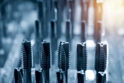
A point tap, also known as a gun tap, is a specialized threading tool designed for threading through holes. It features a twisted and sharp tip.

Due to its twisted and sharp tip, point taps produce chips in a forward direction, preventing chip blockage in the hole. This makes it ideal for trouble-free continuous machining on machines, ensuring stable tapping in mass production scenarios.

However, it is important to note that point taps are not suitable for tapping when a hole has a bottom.

Uses of Point Taps

Point taps find their primary use in machining, especially for large-volume through-holes and continuous machining of mass-produced items.

One of their key advantages is their lower cutting load compared to other taps, resulting in fewer issues like tap breakage and faster processing times. As a result, point taps are preferred in situations where increased productivity and maximum output within a limited timeframe are desired for mass-produced items.

Another benefit of point taps is their resistance to becoming dirty after processing, making it easy to clean both the jig and the final product.

Principles of Point Taps

Unlike hand taps and spiral taps, the tip of a point tap features grooves that direct chips along the blade’s direction. The tap’s design allows chips to slide down these grooves smoothly.

On the other hand, because the tip’s biting portion is cut deeper, point taps cannot reach the bottom of a hole with a hole bottom, and the chips tend to block the hole due to their forward discharge. This makes point taps unsuitable for machining stop holes.

In contrast, spiral taps have spiral-shaped blade grooves that discharge chips in the opposite direction of the tap, preventing chip interference during machining.

Point taps come in two material types: high-speed tool steel (HSS) and cemented carbide. HSS is known for its toughness and resistance to breaking, while cemented carbide is wear-resistant and maintains durability even after continuous machining. Material selection should match the processed material to ensure compatibility.

カテゴリー
category_usa

Threaded Connection

What Is a Threaded Connection?
Threaded Connections

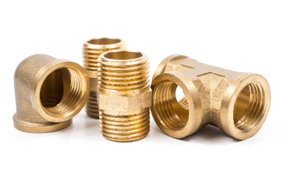
A threaded connection (threaded joint, screw joint, screwed fitting) is a type of pipe fitting.

A pipe fitting is a component used to connect, branch, and close pipes. There are four major types of pipe fittings: threaded connection, welded connection, flanged connection, and ferrule connection.

Threaded connection is one of the four types that can be connected without using special tools or equipment. As a relatively inexpensive piping joint, it is used in a wide range of fields, including power generation and chemical plants, factories, building facilities, and general households.

Applications of Threaded Connection
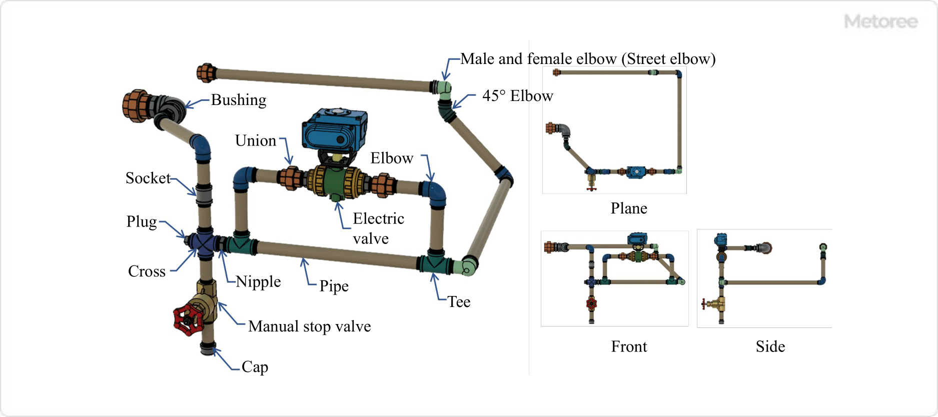
Figure 1. Example of screwed joint use

Figure 1. Example of screwed joint use

Threaded connection is mainly used to connect, branch, and close pipes during piping installation. In most cases, piping routes do not follow a straight line along their entire length, and there are cases in which a pipe route is curved up, down, left, or right, or a single pipe route is branched into two to four pipes, or vice versa, and then assembled. In such cases, threaded connections are required.

Threaded connections are used in many situations in factories, machinery, and homes. However, threaded connections are generally used in piping for low-pressure fluids. For fluids such as high-pressure, high-temperature steam, etc., the possibility of accidents or damage due to leakage exists, so fittings such as plug-in fittings or welded fittings should be used.

As an example, in JIS B2301 threaded malleable iron pipe connection, the maximum working pressure is specified as follows:

Fluid state Max. working pressure
Static water at 120°C or less 2.5 MPa
Steam, air, gases, and oil up to 300°C 1.0 MPa

Principles of Threaded Connection

Threaded connection has a pipe thread machined on one or both ends of the part. The thread shape is specified by various standards, and the typical types are as follows.

Standard Standard No. Standard Name
ISO 228-1 Pipe threads where pressure-tight joints are not made on the threads – Part 1: Dimensions, tolerances and designation
7.1 Pipe threads where pressure-tight joints are made on the threads – Part 1: Dimensions, tolerances and designation
ANSI / ASME B1.20.1 Pipe threads or general -purpose inch
NPS: American National Standard Straight Pipe Threads
NPT: American National Standard Taper Pipe Threads

Tapered pipe threads have a thread outside diameter that decreases toward the tip for male threads and toward the depth of the hole for female threads. For parallel pipe threads, the thread outside diameter is the same over the entire length of the thread for both male and female threads.

Threaded connection prevents leakage of fluid by ensuring that the male and female threads are tightly fitted together. Generally, when used as a fitting for piping, tapered pipe threads are used in many cases because they are more tightly sealed than parallel pipe threads. Sealing tape can be wrapped around the threads or sealing material can be applied to further improve sealing. See figure 2 below for a close fit of the male and female threads.
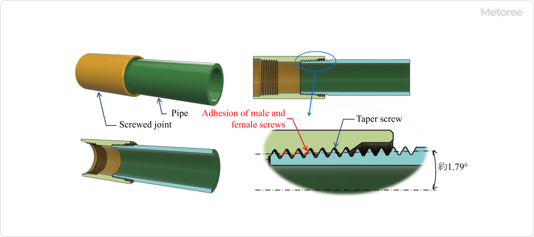
Figure 2. Principle of taper screw

Figure 2. Principles of taper screw

The two types of parallel pipe threads and tapered pipe threads are selected in the following combinations according to the application and required tightness.

Combination of threads Male thread
Tapered pipe thread (R) Parallel pipe thread (G)
Female thread Tapered pipe thread (Rc) ×2
Parallel pipe thread (Rp) ×2
Parallel Thread for Pipe (G)

×1

〇1

Symbol Description
◎: Can be combined with sealing tape for tight joints such as piping.
〇1: Mechanical joints can be combined by using packing or gasket together.
×x1: Combination is not possible due to the possibility of leakage caused by damage to the parallel threads or packing.
×x2: Depending on the screw manufacturing tolerance, it may not be possible to screw in, so sealing cannot be achieved, and the combination is not possible.

Types of Threaded Connections

There are several types of threaded connections depending on the application and direction.

1. Threaded Connections Standards

Standard threaded connections are specified in terms of dimensions, shape, material, and range of application in each standard. Refer to the table below for the various standards of threaded connections.

Standard Standard No. Standard Name
JIS B2301 Threaded malleable cast iron pipe fittings
B2302 Threaded connections for steel pipes
B2303 Threaded drainpipe joints
B2308 Stainless steel threaded connections
ISO 4144 Pipework – stainless steel fittings threaded in Accordance with ISO 7-1

Types of JIS B2301
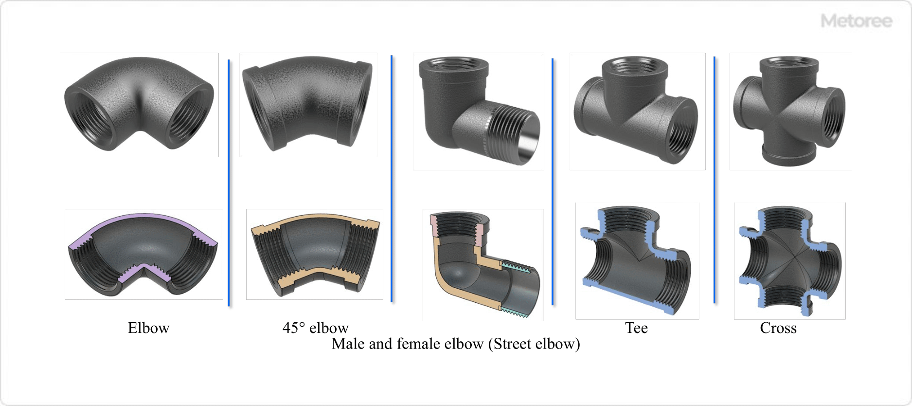
There are many types of threaded connections, and examples of JIS B2301 are shown in the table below. Refer to figures 2 and 3 for their shapes.

Type Uses
Elbow 90° elbow For changing the piping route to 90° or 45°
45° elbow
Different diameter elbow
Male and female elbows (street elbows)
45° Male and female elbows (45° street elbows)
Male elbow with different diameter (different diameter street elbow)
Tee (cheese) Tee with the same diameter Branching (or gathering) piping routes in three directions
Different-diameter tee
Three-way different-diameter tee
Cross Same diameter cross When branching (or assembling) piping routes in 4 directions
Different diameter cross
Sockets Sockets with the same diameter When joining pipes with male threads
Different diameter sockets
Female male socket
Bushing When joining female threaded connections and pipes of different diameters
Nipple Same diameter nipple For joining threaded connections with female threads
Different diameter nipple
Cap To close a pipe with male threads
Plug To close a female threaded connection
Union Same diameter union When female threaded connections are joined and need to be separated
Female male union
Union Elbow
Male Male union elbow

Figure 3. Types of screwed joints (1)
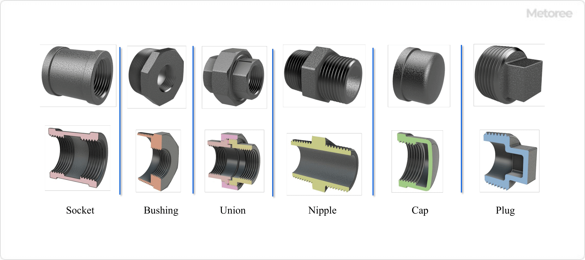
Figure 3. Types of screwed joints (1)

Figure 4. Types of screwed joints (2)

Figure 4. Types of screwed joints (2)

Various sizes are available for each type, and are selected according to the pipe nominal diameter. 

2. Specifications and Sizes of Threaded Connections

Product specifications and sizes of threaded connections are defined by JIS standards and are indicated as follows.

  Standard No. or Standard Name Type Shape Surface condition Joint nominal
Example 1 JIS B 2301 Type I Male and female elbows, different diameter black 2 x 3/4
Example 2 Threaded malleable iron pipe fitting Type I 45° elbow plated 1-1/2
カテゴリー
category_usa

Small Ball Bearings

What Is a Small Ball Bearing?

Small ball bearings, also known as miniature bearings, are compact bearings with an outer diameter of less than 9 mm or an outer diameter of 9 mm or more, and an inner diameter of less than 10 mm. They play a crucial role in reducing friction and maintaining the position of rotating shafts, thereby protecting the components that support rotation. Due to their critical function in many machines with rotating shafts, they are sometimes referred to as the “rice of industry”.

Applications of Small Ball Bearings

Small ball bearings are utilized in a wide range of products, including home appliances, office automation equipment, and hobby equipment. The demand for these bearings is growing rapidly in all industrial fields, driven by the trend towards smaller, lighter, and thinner products. They are found in everyday items such as fishing reels, mini 4WDs, computer hard disk spindle motors, and copier paper feed rollers. Additionally, they are instrumental in downsizing medical equipment and various measuring devices, with applications extending to potential meters, gyro gimbals and rotors, polygon scanner motors, encoders, high-frequency spindles, VTR cylinders, and capstans.

Principle of Small Ball Bearings

The operational principle of miniature bearings is the same as that of standard bearings. They are typically rolling bearings, which include rolling elements like small balls or cylindrical rollers. These elements roll within the bearing, reducing friction and facilitating smooth rotation.

1. Rolling Bearings

Rolling bearings reduce friction by allowing rolling elements to move within the bearing as the shaft rotates. This action helps in supporting the shaft and minimizing friction during operation.

2. Plain Bearings

Unlike rolling bearings, plain bearings (such as bushes) do not contain rolling elements. They rely on materials and lubricants resistant to wear and seizure to support rotational movements. Plain bearings can support larger loads due to their line contact support mechanism, compared to the point contact in ball bearings.

Other Information about Small Ball Bearings

Material of Small Ball Bearings

Small bearings are typically made from heat-treated alloy steel, with high carbon chrome steel used for the inner and outer rings and the balls, and various materials like steel plates, stainless steel, or resin for the cage. Plastic bearings, which can operate without lubrication and are resistant to rust and chemical corrosion, offer an alternative, though they generally have a lower load capacity. Plastics used in these bearings include phenolic resin, PTFE (Teflon), PEEK, PPS, PCTFE (Daiflon), and PP. However, bearings with carbon have high environmental resistance but are not suitable for applications involving high impact, vibration, or insulation requirements due to their conductivity.

カテゴリー
category_usa

Unified Thread Standard

What Is a Unified Thread Standard?

A unified thread standard is an inch-based threading system with standardized basic dimensions in inches and a 60° thread angle.

While metric screws are standardized in metric units, the unified thread standard, including the witt screw, represents inch-based screws. For more information, visit inch screws on Metoree.

Uses of Unified Thread Standards

Unified thread standards are commonly used in aircraft, automobiles, and motorcycles. They are also prevalent in measuring instruments and industrial robots manufactured internationally, particularly in the United Kingdom, the United States, and Canada.

These standards are occasionally used in domestic equipment, primarily when the components are manufactured abroad.

Principles of Unified Thread Standards

The principle of the unified thread standard is similar to that of standard screws. Utilizing the screw’s slope, a heavy object can be lifted with minimal tightening torque, creating a significant fastening or axial force.

The screw remains secure due to the frictional force on the slope, which exceeds the gravitational slope component, thereby maintaining the fastening force. The thread angle of both unified and metric screws is 60°. However, the witt screw has a 55° thread angle.

Types of Unified Thread Standards

Similar to metric screws, unified thread standards come in two types: coarse (UNC) and fine (UNF). The primary difference lies in the thread pitch, with fine threads having more threads per inch than coarse threads. The denser arrangement of fine threads makes them less prone to loosening but requires more turning for tightening, making them less suited for mass production.

Other Information on Unified Thread Standards

Notation of Unified Thread Standards

Unified thread standards are denoted by labels such as UNC and UNF, as well as by fractions. Below is a guide to understanding these notations with an example.

Example: 3/8 – 20UNC x 5/8

1. 3/8: Thread Nominal (thickness)
This refers to the screw’s thickness, including the threads. In inch threads, this measurement is typically expressed as a fraction with 8 as the denominator.

2. 20: Number of Threads Per Inch
This represents the number of thread peaks within a one-inch length. For screws shorter than 1, the thread count is extrapolated to a one-inch length.

3. UNC: Thread Type (Coarse or Fine)
This indicates whether the thread is coarse (UNC) or fine (UNF).

4. 5/8: Length Below the Screw Head
Expressed in fractions of an inch, this length is measured from the base of the screw head to the end of the screw. It includes the length of the unthreaded shank. In tapered head screws, this length corresponds to the total length of the screw.

While the notation generally follows this format, there are unique terms for thread sizes. The thread designation, indicating the screw’s outer diameter, starts with the thinnest (e.g., #0, #1) and goes up to #12.

For sizes larger than #12, the diameter is represented by fractions of an inch, divided into eighths or quarters. These fractions are colloquially referred to as follows:

  • 1/8: one eighth
  • 1/4: two eighths (or one quarter)
  • 5/8: five eighths
  • 5/32: five thirty-seconds
  • 5/16: five sixteenths
カテゴリー
category_usa

End Mill

What Is an End Mill?

An end mill is a cutting tool used in industrial milling applications. It is known for its ability to produce minimal chips during cutting and is particularly effective in machining threads in soft materials. The strength of the threads produced is high, and the effective diameter variations are well-controlled.

End mills come in various designs, some featuring a groove to enhance the supply of cutting fluid.

Uses of End Mills

End mills are commonly used for soft materials like aluminum. While there are end mills designed for steel, they are less effective for harder materials. They are typically used in machine tools rather than by hand due to the high torque required during machining. They are particularly effective for machining stop holes where chip production is a concern.

Various manufacturers provide end mills for machining materials like iron, low carbon steel, low carbon alloy steel, and stainless steel.

Principles of End Mills

End mills work by forming threads through plastic deformation, making the size of the pre-hole crucial for the final thread shape. High-precision control of the pre-hole is essential. For instance, while a M10 x 1.5 thread machined with a spiral or point tap might require a Φ8.5 pre-hole, an end mill would require around Φ9.2.

Using a precise carbide drill is key to achieving high-precision pre-holes. For small-diameter holes with strict dimensional control, high-precision drills are recommended.

For achieving stable, high-precision drilling, using end mills for contouring or boring after pre-drilling with a drill is effective.

It is important to note that end mills are specific to either through-hole or stop-hole drilling and are not interchangeable. Rigid tapping, as opposed to using a tapping collet, is necessary due to the high torque required, ensuring stable thread depth.

カテゴリー
category_usa

Air Grippper

What Is an Air Gripper?

An air gripper is a mechanical device used to hold the inner surface of a workpiece. It operates by expanding a hollow, cylindrical piece of rubber into a doughnut shape when air is injected into it, creating friction to hold the item. Similarly, a gripper that holds the outer surface of a workpiece using this principle is also referred to as an air gripper.

With a broad range of applicable inner diameters (e.g., φ16~21), a single air gripper can handle multiple types of workpieces. Materials used include chloroprene rubber, with silicone as an option for high-heat resistance applications or in the food industry.

Uses of Air Grippers

Air grippers are utilized in the transportation of objects like glass bottles, PET bottles, cans, and printer drums, which can only be handled from the inside. They are also employed in air leak testing for automotive components such as fuel tanks and mufflers, as well as in pumps.

These grippers are advantageous in handling and transporting rolled products like saran wrap, thanks to their ability to grip workpieces of varying diameters with a single size. They are widely used in the end-effectors of industrial and cooperative robots, particularly for gripping the insides of objects.

The silicone variant is chemically stable, exhibiting low temperature dependence and excellent resistance to extreme temperatures. It’s commonly used in the transportation of sensitive materials such as food and garments.

Principles of Air Grippers

Air grippers can grip and release workpieces weighing up to 70 times their own weight. This is achieved by rapidly and reliably injecting and exhausting air, without damaging the workpiece’s surface.

The concentric expansion of the rubber component accommodates workpieces of various diameters using a single size. This versatility reduces the time spent on changing chucks.

However, care is necessary as the rubber can crack or leak over time due to wear or exposure to harsh conditions. Regular checks are needed to avoid damage from sharp objects, UV deterioration, or environmental mismatches.

When dealing with workpieces with low friction coefficients, surfaces covered in substances like oil or water, or shapes prone to slipping, a sufficient safety factor is crucial due to the reliance on friction for holding. The clamping force can be adjusted for fragile parts using an air regulator.

カテゴリー
category_usa

Dust Monitor

What Is a Dust Monitor?

Dust MonitorsA dust monitor, also known as a dust analyzer, is a device used to measure particulate matter in gases. These devices, commonly referred to as dust meters, are employed in monitoring air quality in various environments, including workplaces and building management systems.

Another related device is the particle counter, which measures particulate matter in gases in environments requiring higher cleanliness levels, such as pharmaceutical and medical device manufacturing clean rooms, and in isolators used for quality control.

Uses of Dust Monitors

Dust monitors are typically used in areas with a noticeable presence of airborne particles, contrasting with particle counters designed for cleaner environments. They are ideal for general indoor or outdoor spaces where cleanliness levels are not strictly controlled, as well as in more particle-dense settings like factories.

These monitors are also crucial in measuring fine particulate matter like PM2.5 in the air. However, measuring oil mists and similar substances can be challenging due to potential contamination inside the equipment and varying responses to different types of mists.

Principles of Dust Monitors

Dust monitors utilize various measurement methods, with light scattering and piezobalance (piezoelectric balance) being the most prominent. The light scattering method, which involves measuring scattered light when it interacts with particles in a gas, is a commonly used technique in dust measurement. The amount of scattered light correlates with dust concentration, providing a basis for estimation.

However, the light scattering method assumes uniformity in particle properties. While this allows for consistent measurements when the assumption holds true, mixed particle properties necessitate verification of the measurement’s validity each time.

Conversely, the piezobalance method determines dust concentration by measuring the mass of particles collected on a balance. This method’s advantage lies in its independence from particle properties. The drawback is the need for regular cleaning due to the balance’s limited particle collection capacity.