カテゴリー
category_es

Impresoras de Producción

¿Qué es una Impresora de Producción?

Las impresoras de producción son máquinas utilizadas para imprimir materiales comerciales e internos de forma rápida y precisa. Son capaces de imprimir en una amplia gama de grosores y materiales de papel, así como en diferentes tamaños de materiales. Estas impresoras permiten a las empresas producir sus propios materiales impresos, lo cual puede ahorrar costos en la impresión de tarjetas de visita, sobres, archivos transparentes y papel de ventas que se consumen en grandes cantidades.

Usos de las Impresoras de Producción

Las impresoras de producción se utilizan en diversas aplicaciones, entre las que se incluyen la impresión de grandes volúmenes de material de presentación, la impresión rápida de fotografías a color, la producción de tarjetas de visita, folletos, invitaciones y sobres personalizados con diseños, la impresión de envases de productos, la creación de carteles para publicidad y la impresión de archivos transparentes con diseños.

Estas impresoras son capaces de imprimir rápidamente en una amplia variedad de objetos y materiales, proporcionando resultados vívidos y de alta calidad. Al seleccionar una impresora de producción, es importante considerar las funciones requeridas y otros factores, dado que suelen ser productos de alto costo.

Principio de las Impresoras de Producción

Las impresoras de producción constan principalmente de un alimentador de papel, un tambor fotoconductor, una unidad de proceso de fusión, un sistema de encuadernación y un dispositivo que transporta el objeto impreso al mecanismo correspondiente. El alimentador de papel de una impresora de producción alimenta una gran variedad de objetos impresos a la unidad de proceso de fusión y a otros dispositivos.

Para hacer frente a una amplia gama de materiales impresos, cada una de ellas utiliza aire para hacer vibrar y enrollar el material impreso, a fin de permitir una alimentación suave a altas velocidades.

En el tambor fotoconductor, la luz se convierte en carga eléctrica y el tóner se adsorbe dando una carga estática al objeto impreso. En la unidad de proceso de fusión, el tóner transferido por el tambor fotoconductor se fija mediante tratamiento térmico. De nuevo, el grado de fijación durante el tratamiento térmico varía para adaptarse a una variedad de objetos de impresión.

En los sistemas de encuadernación, cuando los materiales impresos deben cerrarse, como los folletos, se encuadernan mediante tratamiento térmico o perforando agujeros.

Mercado de Impresoras de Producción

En los últimos años, el mercado de impresoras de producción ha ido cambiando.

Por ejemplo, los materiales impresos (folletos, invitaciones, correo directo) como medio para llegar a los clientes están siendo sustituidos por la publicidad en línea que se muestra en portales y motores de búsqueda, en consonancia con el uso generalizado de los teléfonos inteligentes. Al mismo tiempo, la salida de datos en papel de los documentos contables relacionados con las transacciones comerciales se está sustituyendo por un procesamiento descentralizado mediante equipos ofimáticos multifuncionales, o se está volviendo innecesaria en primer lugar debido a la tendencia hacia la impresión sin papel. Así pues, el mercado de impresoras de producción lleva tiempo reduciéndose.

En cambio, las impresoras de inyección de tinta de alta velocidad para uso industrial, que empezaron a introducirse de forma continuada en torno a 2010, han crecido hasta representar un tercio del mercado de impresoras de producción (cifras según el Instituto de Investigación Yano). La razón de este crecimiento es que las impresoras de inyección de tinta no entran en contacto directo con el papel u otros objetos, lo que permite imprimir sobre tela y cartón, sobre los que antes no se podía imprimir. La aparición de impresoras industriales de inyección de tinta de alta velocidad ha propiciado el desarrollo de nuevos mercados que antes no estaban cubiertos por las impresoras de producción, como la impresión de prendas de vestir y envases de pequeños lotes de golosinas, y la tendencia a la contracción del mercado se está frenando.

Impresoras de Producción y POD

La tecnología que permite imprimir el número necesario de ejemplares cuando se necesita se denomina POD (print-on-demand, impresión bajo demanda).

Anteriormente, la impresión de producción era la impresión del mismo contenido en grandes cantidades utilizando medios analógicos (por ejemplo, tipografía, como la utilizada para la impresión de periódicos, que ofrece una excelente calidad de imagen. que ofrece una excelente calidad de imagen) y se refiere a la impresión de grandes cantidades de copias con el mismo contenido. En los últimos años, los avances de la tecnología digital y la tecnología MEMS (sistemas microelectromecánicos) también han introducido en el mercado impresoras de producción con capacidad POD, con capacidades expresivas que superan a las de materiales impresos como los carteles en términos de calidad de imagen.

También se espera que el POD contribuya a la expansión del mercado en el futuro, ya que permite imprimir los nombres de los clientes directamente en folletos y publicidad directa, e imprimir imágenes publicitarias adaptadas a las preferencias de los clientes, hoja a hoja.
カテゴリー
category_es

Bomba de Vacío

¿Qué es una Bomba de Vacío?

Una bomba de vacío es un dispositivo utilizado para extraer el aire o cualquier otro gas de un sistema cerrado y crear un vacío parcial o completo en su interior. Consiste en una bomba, una válvula de escape y una válvula de entrada. Existen diversos mecanismos para generar el vacío en una bomba de vacío.

El vacío incluye vacío bajo, medio y alto, y la bomba de vacío que se vaya a utilizar debe seleccionarse adecuadamente, teniendo en cuenta el vacío necesario, el tiempo que se tarda en alcanzar el vacío y la temperatura ambiente en la que se va a utilizar. Pueden dividirse en bombas secas y húmedas, dependiendo de si se utiliza aceite o no.

Aplicaciones de las Bombas de Vacío

Las bombas de vacío se utilizan en los procesos de fabricación de equipos y dispositivos médicos, fábricas de alimentos, equipos eléctricos y semiconductores. También se utilizan como auxiliares en equipos médicos y científicos que requieren vacío. Se han desarrollado más de diez tipos diferentes de principios de bombas de vacío, y las características de cada uno deben ser entendidas y seleccionadas adecuadamente.

Los principales usos de las bombas de vacío son:

  • Aspiradores de saliva durante los cuidados dentales
  • Creación de secciones de vacío en matraces de vacío
  • Creación de un entorno de vacío cuando se utiliza plasma en procesos de semiconductores
  • Al pegar materiales de envasado de alimentos
  • Fuentes de vacío para equipos científicos y de investigación (evaporadores, filtración, secadores al vacío, desecadores, etc.)
  • Bombas de vacío de gran capacidad para equipos de producción en fábricas

Principios de las Bombas de Vacío

Las bombas de vacío se clasifican según su principio de funcionamiento, y a continuación se describe el principio de funcionamiento de las más comunes.

1. Bombas de Vacío Rotativas Selladas con Aceite

Las bombas de vacío rotativas selladas con aceite son un tipo de bomba de vacío húmeda que utiliza aceite para crear un sello hermético en la bomba. Estas bombas utilizan rotores giratorios y otras partes para aspirar el aire y expulsarlo fuera de la bomba. También se conocen como bombas de vacío rotativas.

Existen diferentes variantes de bombas de vacío rotativas selladas con aceite, como las bombas de vacío de paletas rotativas, las bombas de vacío de levas rotativas y las bombas de vacío de pistones oscilantes. Estas variantes difieren en la forma de las paletas del rotor, la leva o la parte oscilante acoplada al pistón, así como en la parte que entra en contacto con el aire. Sin embargo, en todas las formas, se genera un vacío al expulsar el aire a medida que el rotor gira.

El límite de vacío alcanzable en estas bombas está determinado por la presión de vapor del aceite utilizado. Sin embargo, el aceite también desempeña un papel importante en garantizar un funcionamiento estable de la bomba. Estas bombas son capaces de proporcionar un vacío medio incluso en dispositivos de tamaño pequeño gracias al uso de aceite.

2. Bombas de Vacío por Difusión de Aceite

Las bombas de vacío de difusión de aceite constan de una caldera, una tobera de chorro y un condensador. El aceite calentado a vapor en la caldera es inyectado a velocidad supersónica por las toberas de chorro, empujando las moléculas de aire del interior de la bomba hacia la lumbrera de escape. El aceite vaporizado se convierte en aceite líquido en el condensador y se reutiliza.

3. Bombas de Vacío Secas de Paletas Rotativas

Las bombas de vacío secas de paletas rotativas son bombas de vacío exentas de aceite con un rotor giratorio y paletas que expulsan el aire aspirado por el orificio de entrada agitándolo. Como no se puede evitar el reflujo de aire, las condiciones de bajo vacío son la limitación, pero se pueden alcanzar grandes velocidades de bombeo.

4. Bombas de Vacío Secas de Pistón Oscilante

Las bombas de vacío secas de pistón oscilante son bombas de vacío que utilizan un pistón unido a un eje giratorio excéntrico para expulsar el aire. Debido a su estructura, no pueden impedir que el aire fluya hacia atrás, por lo que están limitadas a condiciones de bajo vacío, pero son fáciles de mantener. 

5. Bombas de Vacío Secas de Membrana

Las bombas de diafragma (bombas de membrana) combinan el movimiento alternativo de una membrana de caucho, resina o metal con una válvula de retención para transportar el fluido. Cuando se utiliza como bombas de vacío, la válvula de retención elimina la necesidad de utilizar aceite para la estanqueidad y permite utilizar la bomba como bomba seca. Con movimiento alternativo, el aire es aspirado repetidamente desde el lado a evacuar y descargado a la atmósfera para crear el vacío.

6. Bombas de Vacío Secas tipo Scroll

Son bombas de vacío en seco que agotan el aire mediante una combinación de movimiento de voluta del estator y del rotor. El movimiento de la voluta atrae el aire hacia el centro y lo expulsa por el centro.

7. Bombas Turbomoleculares

Las bombas turbomoleculares son bombas de vacío secas en forma de turbinas. Los álabes de la turbina giran a gran velocidad, cerca del movimiento térmico de las moléculas, y expulsan el aire creando un sesgo en el movimiento molecular en función de la inclinación de los álabes de la turbina. Para que los álabes de la turbina puedan girar a altas velocidades, la bomba debe utilizarse en un cierto grado de vacío y se utiliza en combinación con otras bombas de vacío.

¿Cómo Elegir una Bomba de Vacío?

Al seleccionar una bomba de vacío, el tipo de bomba viene determinado por el grado de vacío alcanzado, el tiempo de bombeo y la capacidad de bombeo. Los grados de vacío incluyen bajo vacío, medio vacío y alto vacío, y existe una bomba de vacío adecuada para cada uno de ellos.

1. Bombas de Vacío para Bajo Vacío

Para bajo vacío, existen bombas secas de diafragma, bombas secas de pistón oscilante y bombas secas de paletas rotativas. Las bombas secas de membrana no tienen piezas deslizantes como las bombas secas de paletas rotativas, por lo que no generan partículas debido a la agitación y pueden producir un vacío limpio. El tipo de pistón oscilante tiene una estructura sencilla y es fácil de mantener. Las de paletas rotativas pueden alcanzar altas velocidades de bombeo. 

2. Bombas de Vacío para Vacío Medio

Para aplicaciones de vacío medio existen bombas de tipo scroll y rotativas de aceite. Muchas de las bombas scroll utilizan compresión en dos etapas para garantizar su eficacia y son silenciosas y producen pocas vibraciones. Como su nombre indica, las bombas rotativas de aceite están lubricadas y selladas con aceite, lo que se traduce en un alto rendimiento y una buena estabilidad del vacío.

3. Bombas de Vacío para Alto Vacío

Las bombas de vacío para alto vacío incluyen bombas de vacío tipo Roots (booster mecánico) que succionan y comprimen mediante la rotación de dos rotores, bombas de vacío tipo Roots multietapa que integran múltiples bombas tipo Roots, y bombas de vacío tipo difusión de aceite con una estructura simple y alta velocidad de bombeo. Además, existen bombas turbomoleculares y criobombas para lo que se denominan aplicaciones de vacío ultraalto.

Dado que existen muchos tipos diferentes de bombas de vacío, es importante conocer bien sus características y seleccionar la más adecuada para cada aplicación.

Formas de Utilizar las Bombas de Vacío

En los equipos que utilizan vacío, la elección de la bomba de vacío se basa en el grado de vacío alcanzado y en el tiempo de bombeo. Sin embargo, como la velocidad de bombeo suele disminuir a medida que aumenta el nivel de vacío, y algunas bombas para alto vacío no pueden utilizarse en condiciones de presión atmosférica, a veces las bombas de vacío se utilizan combinadas y no solas.

Por ejemplo, alternar entre “bombas con bajo vacío y alta velocidad de bombeo” y “bombas para alto vacío”, o utilizarlas juntas o simultáneamente, puede proporcionar cierto grado de velocidad de bombeo incluso en alto vacío.

Un ejemplo concreto es utilizar una bomba rotativa de aceite para aspirar un vacío bajo (desbaste) y, a continuación, cambiar a una bomba mecánica de refuerzo para aspirar un vacío alto (aspiración principal).

Otra posibilidad consiste en conectar dos tipos de bombas de vacío e interponer una bomba para medio y bajo vacío, de modo que se pueda utilizar una bomba para alto vacío incluso a presión atmosférica.

Más Información sobre Bombas de Vacío

Bombas de Vacío Accionadas por Aceite

Las bombas de vacío rotativas accionadas por aceite proporcionan un rendimiento estable cuando se utilizan correctamente, pero la gestión del aceite es importante. Debido a la naturaleza del vacío creado por la aspiración de gases, las impurezas (por ejemplo, el agua) de la aspiración se mezclan inevitablemente con el aceite. Estas impurezas degradan el rendimiento del aceite.

La mayoría de las bombas de vacío rotativas selladas con aceite tienen una función llamada lastre de gas, que evapora los componentes volátiles, por lo que es aconsejable realizar el lastre de gas de forma regular.

カテゴリー
category_es

Terminales Portátiles

¿Qué es un Terminal Portátil?

Los terminales portátiles son dispositivos altamente portátiles que permiten recopilar de manera sencilla datos almacenados en códigos de barras y códigos 2D.

Estos terminales se encuentran disponibles en una amplia gama de tamaños, desde modelos más grandes hasta opciones más compactas. Algunos modelos incluso cuentan con funciones de reconocimiento de caracteres, lo que les permite leer información que va más allá de los códigos de barras y los códigos 2D. Además de la recolección de datos, estos dispositivos ofrecen otras funcionalidades, como la transmisión y recepción de datos, almacenamiento de información, teclado para introducción de datos y pantalla para visualización.

Además, existen diversos tipos de terminales portátiles que se adaptan a los entornos específicos en los que se utilizan. Por ejemplo, hay modelos diseñados para entornos médicos que pueden ser desinfectados con productos químicos adecuados, dispositivos antideflagrantes especialmente diseñados para zonas con riesgo de explosiones, y terminales con sistemas de refrigeración para su uso en almacenes con temperaturas bajo cero.

Usos de los Terminales Portátiles

Los terminales portátiles se utilizan en una gran variedad de aplicaciones empresariales como terminales portátiles que pueden recopilar datos fácilmente, por ejemplo:

  • Recogida y gestión de paquetes en el sector del transporte.
    La información de entrega, la comunicación con el cliente, la navegación y la gestión de dinámicas pueden realizarse con un único terminal portátil equipado con Android.
  • Gestión de recepción y envío en la industria logística
    Se puede mejorar la eficiencia del trabajo mostrando la información de las estanterías de productos mediante una gran pantalla y enlazando con los sistemas de gestión de almacenes.
  • Gestión de materias primas y procesos en los sectores manufacturero y farmacéutico, etc.
    La gestión de procesos en tiempo real puede lograrse mediante una introducción de datos eficaz y precisa.
  • Gestión de pedidos y materiales en los sectores minorista y de restauración.
    Los pedidos pueden compartirse en tiempo real con la cocina y el back office para aumentar la eficacia y reducir el tiempo.
  • Lectura de contadores de agua, electricidad y gas
    El trabajo puede ser más eficiente y la información personal puede gestionarse de forma fiable.

Principios de los Terminales Portátiles

Las funciones y especificaciones requeridas para los terminales portátiles varían ampliamente según la aplicación y el entorno de uso. Sin embargo, las principales funciones que abarcan estos dispositivos son la lectura de datos, visualización y manejo de la pantalla, y comunicación, y se basan en los siguientes principios:

1. Función de Lectura de Datos

La función de lectura de datos permite la captura de códigos de barras, códigos QR y otros códigos y caracteres 2D presentes en productos. Esto se logra mediante la irradiación de los códigos con un láser o un LED y su posterior conversión en números, letras y símbolos de acuerdo con reglas específicas.

2. Visualización en Pantalla

Los LCD se utilizan principalmente para la visualización en pantalla, que muestra caracteres, gráficos e imágenes bajo el control de la CPU.

3. Funciones Operativas

Las funciones operativas se realizan mediante un teclado o un teclado numérico para introducir cantidades, etc., o mediante un panel táctil integrado en la pantalla. La CPU descodifica la información introducida y la reconoce como letras, números o símbolos.

4. Funciones de Comunicación

Las funciones de comunicación se realizan principalmente a través de LAN inalámbrica o Bluetooth. El terminal se conecta a un ordenador central o a otros terminales a través de Internet o de una red interna, y la fecha, la hora y los datos del producto leídos se almacenan en el terminal y, a continuación, se transmiten y reciben en tiempo real al ordenador central o a otros terminales.

¿Cómo Elegir un Terminal Portátil?

Existen varios modelos de terminales portátiles. Para elegir el producto adecuado entre los numerosos modelos, elija el que mejor se adapte a su negocio, su entorno operativo y su presupuesto.

1. Contenido Empresarial

Las aplicaciones necesarias dependen de la naturaleza del trabajo. Muchos terminales de mano están equipados con el sistema operativo Android, pero las aplicaciones que pueden utilizarse dependen de la versión del sistema operativo. Compruebe si se proporcionan las aplicaciones necesarias.

También se tienen en cuenta los requisitos especiales, como la necesidad de un botón PTT específico para lectores RFID e intercomunicadores. 

2. Entorno de Uso

En función del entorno del lugar donde se vaya a utilizar el sistema, puede ser necesario un modelo que satisfaga condiciones ambientales especiales, como las de tipo médico, a prueba de explosiones o refrigerado.

3. Costo

El coste, calculado a partir del presupuesto y la rentabilidad, es otra consideración importante. No sólo se tiene en cuenta el coste de compra del terminal portátil, sino también los costes de mantenimiento.

Más Información sobre los Terminales Portátiles

Diferencias entre Terminales Portátiles y Escáneres Portátiles

Los terminales portátiles son más sofisticados que los escáneres de mano. Los terminales portátiles son más versátiles y tienen un amplio abanico de aplicaciones, mientras que los escáneres de mano se utilizan para leer datos de TPV de productos, leer datos de préstamo de bibliotecas, etc., debido a su única función pero menor precio.

カテゴリー
category_usa

Ultrasonic Flaw Detector

What Is an Ultrasonic Flaw Detector?

Ultrasonic Flaw Detectors

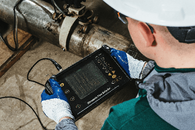
An ultrasonic flaw detector is a device that can measure internal flaws using ultrasonic waves.

It is used in various places as a nondestructive inspection device because it can check internal flaws without having to make an incision in the object. Ultrasonic waves are applied from the surface of the object to detect damage, and the sound waves reflected through the interior of the object are detected. It is possible to check not only the presence or absence of scratches, but also their location and size, and is used to inspect for defects in the manufacturing process of various products.

Uses of Ultrasonic Flaw Detectors

Ultrasonic flaw detectors can measure flaws that occur in various locations.

An example is the measurement of defects during welding. Welding is a method of joining parts by melting metal, and while it is an essential process for manufacturing industrial products, it is often performed by hand and is prone to human error and defects. To prevent serious accidents from occurring, quality inspections are conducted using ultrasonic flaw detectors.

It is also used to check the bonding condition: when two identical materials are bonded, ultrasonic waves penetrate the boundary surface and do not bounce back, but if there is delamination, they will be reflected in that area. By detecting this, the state of adhesion can be checked.

Principle of Ultrasonic Flaw Detectors

Ultrasonic-Flaw-Detectors_超音波探傷器-1

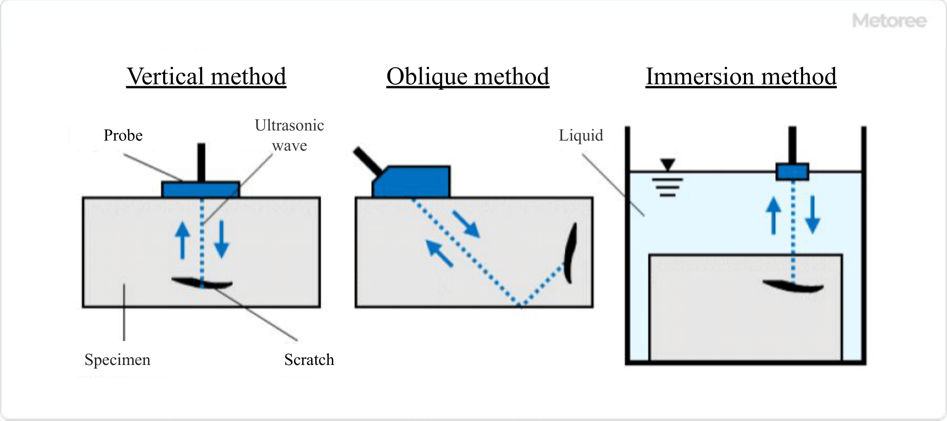
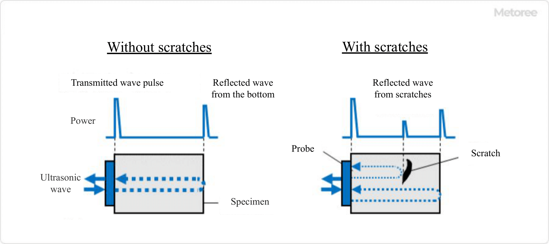
Figure 1. Principle of ultrasonic flaw detector

The ultrasonic flaw detectors use the reflection of ultrasonic waves to identify the presence, position, size, etc. of flaws, and the principle is called the pulse reflection method.

A probe capable of transmitting and receiving ultrasonic waves is placed on the surface to be inspected. The ultrasonic waves incident on the object from the probe are reflected by the bottom surface or internal flaws and then returned to the probe. By observing this reflected wave, the condition of the inside of the inspection object can be estimated.

If there is a flaw inside, the received waves are observed in the order of the transmitted wave pulse, the reflected wave from the flaw, and the reflected wave from the bottom surface. The position and size of the flaw are estimated from the time it takes for the waves to be observed and the strength of the waves.

Other Information on Ultrasonic Flaw Detectors

1. Classification of Ultrasonic Flaw Detectors

Ultrasonic-Flaw-Detectors_超音波探傷器-2.

Figure 2. Classification of ultrasonic flaw detector

There are several types of ultrasonic flaw detectors.

Depending on the angle of incidence of the waves, they can be classified into two methods: the vertical method, in which the waves are incident perpendicular to the object to be inspected, and the oblique method, in which the transverse waves are incident obliquely to the object to be inspected. The oblique method is especially used for inspecting welds.

Depending on whether the probe is applied directly to the inspection object or not, the two methods can be classified into two types: the direct contact method, in which the probe is directly applied to the inspection object, and the water immersion method, in which the inspection object is submerged in a liquid and ultrasonic waves are injected through the liquid. The water immersion method can be further classified into the full immersion method and the partial immersion method.

2. Example of Inspection Using Ultrasonic Flaw Detector

Ultrasonic-Flaw-Detectors_超音波探傷器-3

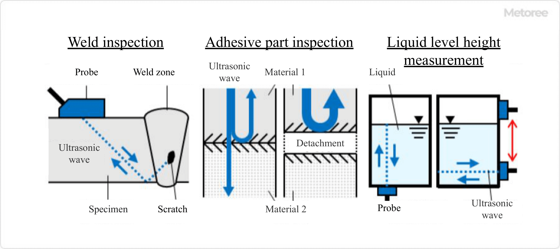
Figure 3. Example of inspection using an ultrasonic flaw detector

Ultrasonic flaw detectors can be used in various ways depending on its intended use. Typical uses are as follows

1. Inspection during welding
Ultrasonic flaw detectors are used to inspect defects such as shape defects and metal cracks that occur during welding. When applying ultrasonic waves, the ultrasonic waves are applied to the weld area from an angle to check for defects. To avoid missing any defects by applying ultrasonic waves at an angle, the ultrasonic waves are reflected once on the backside of the object and then applied to the object.

2. Inspection of bonded area
When two materials are bonded, ultrasonic waves are applied to them to check whether the bonding is sufficient. If the same materials are sufficiently bonded, ultrasonic waves will not be reflected, but if there is a gap due to peeling in the bonded area, ultrasonic waves will be reflected, allowing the accuracy of the bond to be checked.

In the case of different materials, reflection always occurs at the boundary surface, and if delamination occurs, the phase of reflection is shifted or reversed, which can be confirmed as a defect.

3. measurement of the liquid level height of liquid sealed in a container
For liquids that easily vaporize or hazardous chemicals, it is necessary to measure the presence or absence and quantity of the contents in a sealed container without opening it.

The ultrasonic testing device is used to apply ultrasonic waves from the bottom of the container. The ultrasonic waves travel through the liquid and are reflected at the liquid surface, so the volume can be measured from the height of the solution’s water surface.

カテゴリー
category_usa

Ultrasonic Homogenizer

What Is an Ultrasonic Homogenizer?

An ultrasonic homogenizer is a device that homogenizes particles and liquids by irradiating a particle-containing liquid with ultrasonic waves.

Particles can be solids or droplets within a liquid. Ultrasound generates very small bubbles (ranging from several hundred to tens of micrometers) in the liquid. When these bubbles burst, they create turbulence in the solution.

This turbulence impacts the particles, crushing large ones and atomizing them, thereby dispersing particles to homogenize the solution. Ultrasonic homogenizers can prepare stable homogenized suspensions and emulsified liquids, even where ordinary mechanical stirring is ineffective.

Applications of Ultrasonic Homogenizers

Ultrasonic homogenizers are used in various applications, notably for producing stable homogenized liquids such as suspensions and emulsions.

1. Food and Dairy Production

In food and dairy processing, ultrasonic homogenizers create dispersions and emulsions, ensuring product stability and quality.

2. Manufacture of Cosmetics

In cosmetics manufacturing, their ability to achieve stable emulsification aids in producing high-quality creams, lotions, and similar products.

3. Other

Ultrasonic homogenizers also adjust the stability and viscosity of dispersions and suspensions in ceramics, pigments, minerals, etc. They are used in biology and microbiology, research and development for cell tissue and virus disruption, and DNA and protein extraction. Their use extends to materials research, particularly for suspension and emulsification processes.

Principle of Ultrasonic Homogenizer

1. Generation of Ultrasonic Waves

An ultrasonic homogenizer’s key components include an oscillator and a transducer. The oscillator emits an electrical signal, causing the transducer’s tip (or horn) to vibrate vertically at approximately 20,000 times per second.

These vibrations, when transmitted to the liquid, propagate as ultrasonic waves.

2. Cavitation

As sound waves are longitudinal, they create high and low-density areas in the liquid, forming vacuum bubbles in low-density zones. This phenomenon, known as cavitation, produces these bubbles.

3. Crushing, Dispersion, and Homogenization

When a bubble bursts, it generates powerful turbulence, breaking up agglomerated particles. This process, repeated through cavitation, refines particles in the liquid, enhancing homogenization.

Features of Ultrasonic Homogenizer

The key features and considerations of ultrasonic homogenizers are as follows:

1. Relatively Low Risk of Foreign Matter Contamination

Unlike conventional mechanical homogenizers with many contact surfaces, ultrasonic homogenizers have fewer contact points and do not physically interact with particles, thus reducing contamination risk.

2. Low Maintenance and Management Costs

As no physical force is applied for crushing, equipment wear due to friction is minimized, thereby reducing maintenance and management costs.

3. Suitable for Homogenizing Particle Size Distribution

In the final homogenization stages, particulation is primarily due to particle collisions, often resulting in spherical particles. This is ideal for achieving uniform particle size distribution.

4. Excessive Breakdown of Components May Occur

The high energy of ultrasound can be overly destructive, especially for biological samples where cell disintegration can occur. However, this property is sometimes desirable, such as in cell disruption processes.

5. Heat Generation

The heat generated during use can denature proteins in biological samples. Therefore, optimizing processing time and irradiation intervals with cooling is necessary.

カテゴリー
category_usa

Load Switch

What Is a Load Switch?

A load switch is a device designed to either open or close an electric circuit carrying a load current. Typically, it refers to a product used for controlling high-voltage AC load currents.

Moreover, Load Break Switch (LBS) is often included in this category. Devices responsible for opening and closing circuits in high-voltage electrical lines encompass disconnectors, circuit breakers, and load switches.

A disconnector is a device that cannot interrupt the load current and is primarily used for safety control during maintenance tasks. On the other hand, a circuit breaker is capable of interrupting both load currents and fault currents during short circuits, and it finds extensive use in main power receiving equipment and power distribution systems.

A load switch can control load currents but cannot interrupt high-current short-circuit events. Generally, load switches are combined with current-limiting fuses to safeguard upper circuits against accidental overcurrents.

Applications of Load Switches

Load switches are widely deployed in high-voltage transmission and distribution circuits. Here are some examples of load switch applications:

  1. Connecting lines for commercial facilities supplied with high-voltage power
  2. Located upstream of transformers that step down high voltage to low voltage
  3. Located upstream of high-voltage phase advance capacitors
  4. Located upstream of high-voltage motors

The first type is often installed on utility poles, and it utilizes air-load switches. The second and third types are frequently situated inside cubicles, where LBS is employed. The fourth type is typically found in factories and infrastructure facilities and utilizes vacuum electromagnetic switches. The fifth type is generally installed in factories and employs vacuum electromagnetic switches.

Principle of Load Switches

A typical load switch, such as LBS, comprises a main contact, an operating mechanism, and a current-limiting fuse.

1. Main Contact

The main contact is a metal component that allows the flow of electric current. In LBS, the main contact often consists of a blade and a blade holder. It becomes energized when the blade is inserted into the holder.

Interrupting the load current in a high-voltage circuit can lead to an arc discharge phenomenon. This involves electrical discharge through tiny airborne metal particles, which can break down air insulation. To prevent extended arc discharge, an arc chute is frequently installed in the blade receptacle of LBS.

2. Operating Mechanism

The operating mechanism is a structural component responsible for opening and closing operations. The simplest design consists of an operating handle attached to the blade, which is opened and closed using an operating rod made of insulating material. Electrically operated LBSs are also available for those requiring interlocks and other features.

3. Current-Limiting Fuse

Current-limiting fuses are components installed to interrupt a circuit in the event of a short circuit in the downstream wiring. Inside the fuse, there is a fuse element and silica sand. In the event of a short circuit, the fuse element breaks, and the silica sand extinguishes the arc, providing protection.

Strictly speaking, current-limiting fuses are not part of the load switches, as they can interrupt fault currents, but they are typically installed together.

Types of Load Switches

While load switches commonly refer to LBSs, there are other types, including air load switches and vacuum load switches.

1. Air Load Switches

Air-load switches are employed to switch the load on and off in high-voltage circuits and are also known as PAS (Pole Air Switches). They are often installed at the point where transmission and distribution companies connect with customers.

Since PAS itself does not provide overload or ground fault protection, it is frequently combined with an SOG (Storage Over Current Ground).

2. Vacuum Load Switches

Vacuum load switches utilize a vacuum to extinguish arcs around the contacts. They are often equipped with a current-limiting fuse and are also referred to as high-voltage combination units or VCS (Vacuum Circuit Switches).

The principle is similar to that of vacuum circuit breakers, and many products are operated by electromagnetic coils. Even with frequent load current switching, arcing is unlikely due to this principle, and the fuse melts faster than typical circuit breakers.

カテゴリー
category_usa

CAD

What Is CAD?

CAD is software used to create mechanical and architectural drawings.

In the past, all drawings were created by hand, which required an enormous amount of work time. Today, CAD allows drawings to be digitized, greatly reducing the time spent on drawing.

There are two main types of CAD: 2D and 3D.

While 2D CAD has been the most common type of CAD, more and more companies are adopting 3D CAD in recent years.

3D drawings created with 3D functionality can be expanded into a plan view and viewed from any angle. In fact, manufacturing and construction companies use CAD drawings as the basis for their production.

CAD with 3D functionality has different areas of expertise depending on the software sold. It is divided into a solid type suitable for structural drawing and a surface type suitable for design drawing and can be selected according to the purpose of use.

Uses of CAD

The use of CAD depends on the purpose of the created drawings: 2D CAD drawings are used for dimensional control of manufactured products, while 3D CAD drawings are used to grasp the shape of manufactured products.

With 2D CAD, hand-drawn drawings can be digitized, but visual spatial recognition is not possible. On the other hand, 3D CAD makes it easy to visualize the completed product, but the time and cost required for the work are inflated. In design companies, 2D CAD and 3D CAD are used in parallel for product development, so drafting CAD is used for different purposes.

Principles of CAD

Line data in 2D CAD is composed of shape parameters such as lines and circles, and position parameters such as start point, endpoint, and center point. Various shapes can be expressed by adding information such as color, line type, and line thickness to the line segment.

1. Solid Type 3D CAD

A shape drawn on a specified plane can be moved in three dimensions to create a three-dimensional object based on the trajectory of the shape. For example, drawing a rectangle on a plane and moving the rectangle perpendicular to the plane creates a rectangle. It is often used in mechanical design where the image of processing is easy to imagine.

2. Surfaces Type 3D CAD

A plane is created by connecting line segments, and a three-dimensional object is created by joining the two planes.

This CAD software can draw smooth curved surfaces by connecting curves to curves, and by editing the line segments in the middle of the curved surface, it is possible to create even more diverse curved surfaces.

Other Information About CAD

Qualifications for CAD

CAD is a design method used in all fields of mechanical, electrical, and architectural design, etc. Some examples of CAD certifications are listed below.

1. CAD User Engineer Examination
This is the largest CAD certification examination in Japan. The examinations are subdivided by purpose, such as Tracing Level 1, Architecture Level 1, Machinery Level 1 and 2, and the Basic Examination. The pass rate is about 80% for basic exams and about 30-40% for other grades.

2. Architectural CAD Certification Examination
This is said to be the largest architectural exam. The examinations are classified into levels such as Level 1, Level 2, Level 3, and Level 4, and the higher the level, the lower the passing rate. In the 1st grade, which has a pass rate of about 10%, there is an exam in which you trace a given assignment drawing. The amount and density of the drawings are almost the same as the design drawing test for the first-class architect examination, so a high level of technical ability is required.

3. CAD Practice Career Certification System
This system evaluates and judges the skills, techniques, and morals required for practical work, and is sometimes used for corporate training.

4. Autodesk Certification Program
This is a certification program sponsored by the well-known CAD software AutoCAD and is a suitable examination to prove the technical ability of AutoCAD.

5. Mechanical and plant drafting technician
This is a national certification for draftsmen. Courses are divided into two types: hand-drawn and CAD. The government guarantees the skills of the applicant, so it is a highly reliable examination.

カテゴリー
category_usa

Surface Resistance Meter

What Is a Surface Resistance Meter?

A surface resistance meter is a machine that measures the resistance of antistatic products. Various measurements are possible by using optional probes and stainless steel plates.

An object that is an insulator is always charged with static electricity, which causes deterioration, resulting in ground fault and electric shock. Therefore, by measuring surface resistance and insulation resistance, it is possible to predict the deterioration of the object over a long period.

Also, for materials such as water-based paints and concrete, which contain water and harden when the water is removed during drying, it is possible to measure how much water is contained in them.

Especially in the film forming process called “chocolate type,” in which water solvent volatilizes and forms a film, moisture control is a major issue, so it is used in the moisture control process.

Uses of Surface Resistance Meters

Surface resistance meters are used to measure the working environment, mainly for periodic inspections in clean rooms where electronic components are manufactured.

They can also be used for process control and quality control to measure the moisture content of a product’s surface using its resistance value and thus can be used to check the drying condition of paint or concrete.

Many portable types use probes to measure the resistance between two surface points by placing two probes on the surface or to measure the groundable junction resistance by placing one probe on the surface and touching the surface with the other probe.

Surface resistivity can also be measured by placing surface resistance meters on the surface without probes. In addition, volume resistivity can be measured by placing a stainless steel plate on an insulator plate and placing one probe on the stainless steel plate and the other on the object to be measured.

Principle of Surface Resistance Meters

The principle of the surface resistance meters is derived from an electric circuit, where the current value applied from the resistivity meter and flowing to the object is measured and calculated from the applied voltage and current amount, and the voltage between the probes is calculated from the current value flowing to the object, depending on the purpose of the measurement.

In addition, there are surface resistance meters that tentatively measure temperature and humidity, since the measured values may differ due to moisture in the air when the humidity in the air exceeds 60%.

Some surface resistance meters not only indicate resistance values but also indicate conductors, antistatic materials, or insulators so that they can be easily determined.

Also, surface resistivity can be measured by attaching a surface resistance meter to the surface without using a probe. Furthermore, the volume resistance can be measured by placing a stainless steel plate on the insulator plate and placing one probe on the stainless steel plate and the other on the object to be measured.

カテゴリー
category_usa

Counting Chamber

What Is a Counting Chamber?

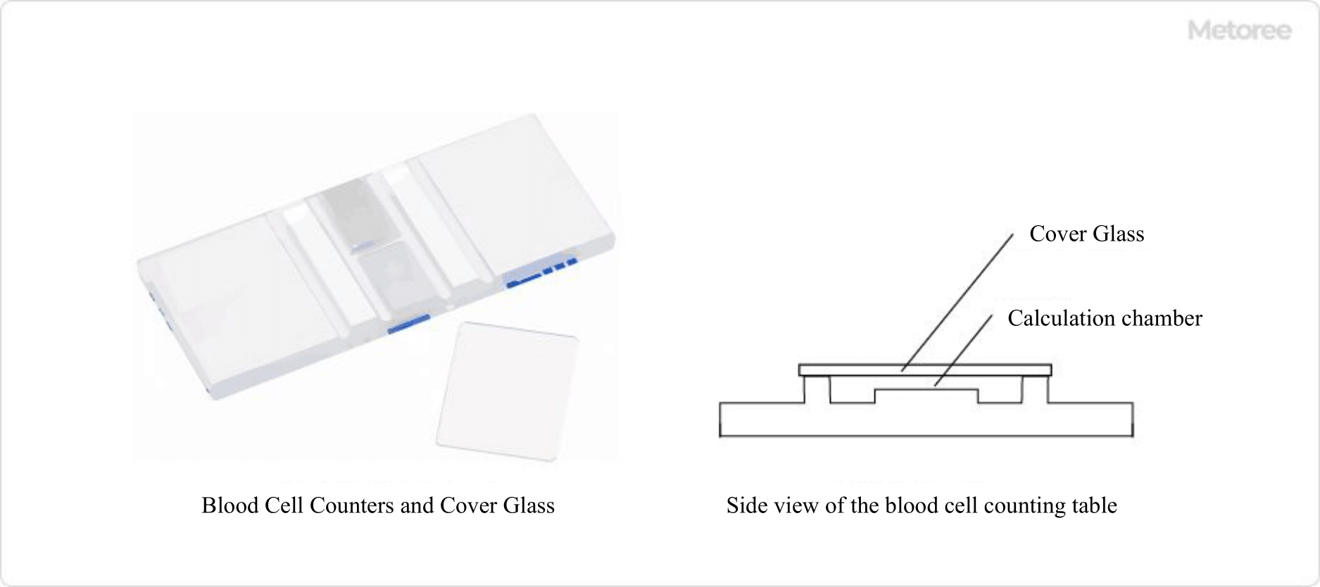
3434_Counting-Chambers_血球計算盤-1.png

Figure 1. Overview of the blood cell calculator

A counting chamber is a tool used to count cells. It is also called a hemocytometer.

It is used for this purpose because it is necessary to count cells prior to cell fusion techniques or cell culture operations.

The size of cells varies depending on the object to be measured, such as blood cells (red blood cells, white blood cells, etc.), lymphocytes, or other cultured cells. For this reason, the scale width of the counting chamber is also different depending on the object to be measured.

Uses of the Counting Chambers

The counting chambers are used in research and development of cell-related technologies. By calculating cell counts, it is possible to calculate cell density, survival rates, and other necessary values. This is always done as a preliminary preparation for cell culture operations such as transfection, cell fusion technology, cryopreservation, etc.

Principle of the Counting Chambers

The counting chambers have series of equally spaced tick marks of different widths, each of which can be used to calculate a numerical value. The concentration of the suspension is adjusted so that there are about 100 cells within a frame of 1 mm per side, and the number of viable cells within a frame consisting of 16 squares is counted.

How to Use Counting Chambers and Cover Glass

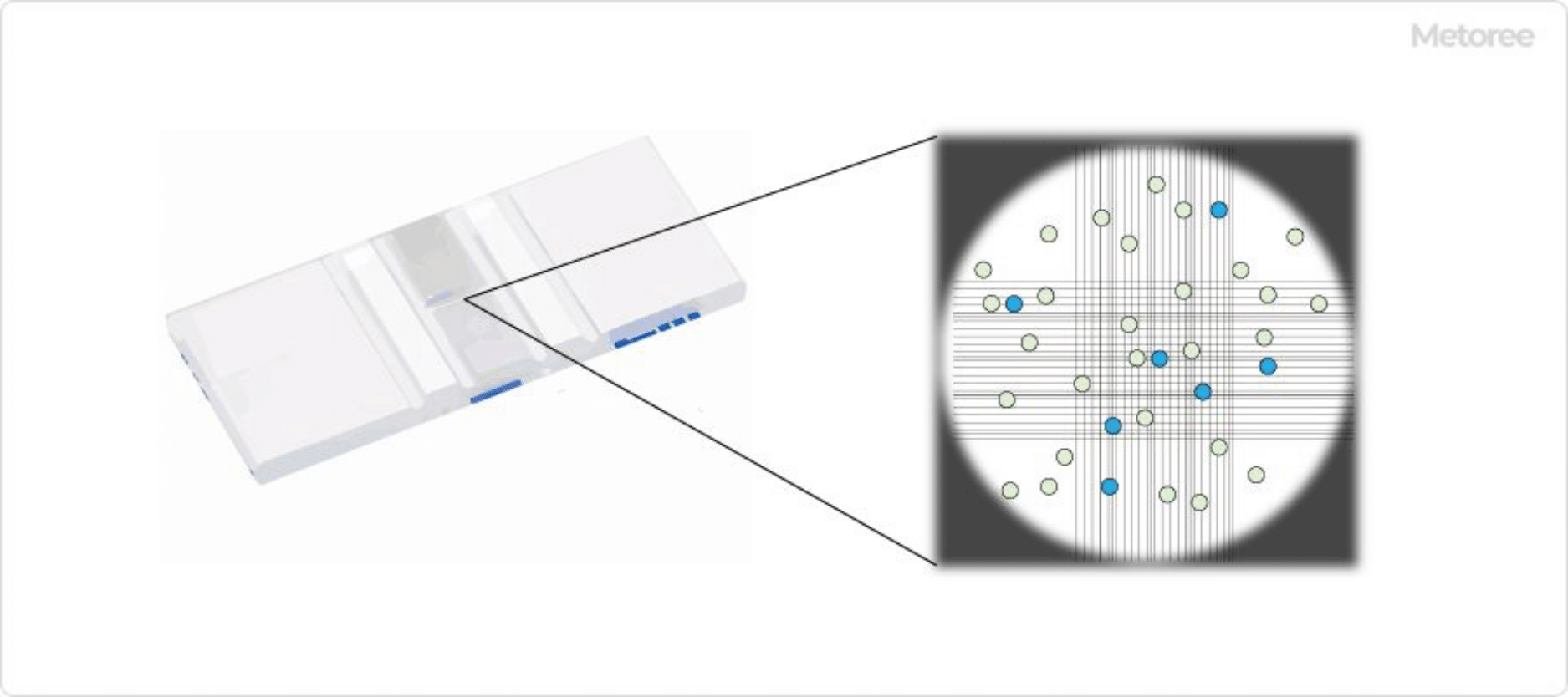
3434_Counting-Chambers_血球計算盤-2.png

Figure 2. Image of how a cell looks

1. Counting Chambers

First, the cells to be observed are collected and resuspended in culture medium, from which the cell suspension is collected and colored with a dye to classify live and dead cells. Dead cells are colored, but living cells are not, so the presence or absence of color is used to distinguish between living and dead cells.

It is important to adjust the concentration of the suspension to an appropriate level so that there are about 100 cells in the frame because if the concentration is too high, it is difficult to measure, and if it is too low, it cannot be measured correctly. Initially, the number of viable cells within a 1 mm square frame, the largest of which consists of 16 squares, is counted.

By measuring the number of live and dead cells through this operation, the cell viability can be calculated.

2. Cover Glass

The counting chambers are used with a cover glass adhered to it. The cover glass should be washed with ethanol and air-dried before use. Just before use, moisten the cover glass lightly with water and place it on the scale surface of the counting chambers. While being careful not to break the cover glass, apply light pressure as if rubbing the cover glass with your fingers to make it adhere closely to the counting chambers.

At this point, check for the presence of Newton rings to confirm that the glass is firmly adhered. Newton rings are rainbow-colored interference fringes that occur when glasses with the same percentage curve on their surfaces are superimposed on each other. They are not visible if dust or other contaminants have penetrated between the counting chambers and the cover glass.

If the Newton rings cannot be confirmed, wipe the surface of the counting chambers and the cover glass with a gauze or similar cloth moistened with an appropriate amount of ethanol, and repeat the same procedure. Note that the depth of the calculation chamber will change with dirt in it, and accurate counting will not be possible.

Some disposable products do not require a cover glass. In such cases, the labor of Newton ring creation can be eliminated.

Types of Counting Chambers

3434_Counting-Chambers_血球計算盤-3.png

Figure 3. Various types of scales

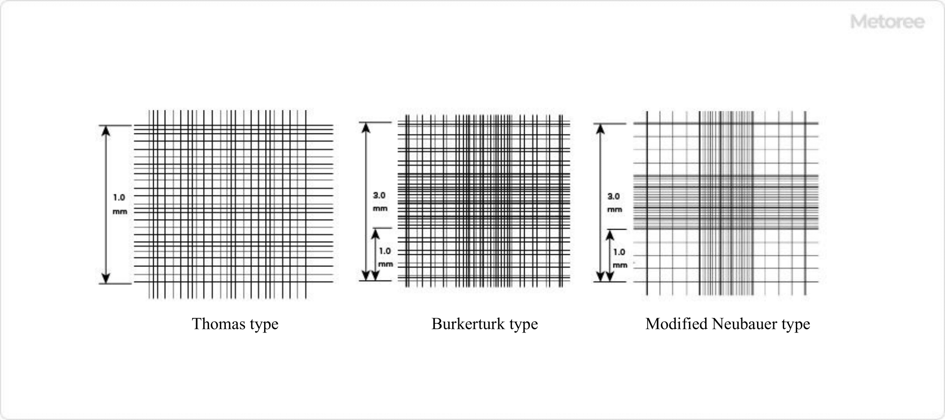
1. Bürker-Türk Type Counting Chambers

There are several types of counting chambers, each with a different scale inscription and depth of calculation chamber. The most commonly used type is the Bürker-Türk type counting chambers.

It is a duplex calculator with two calculation chambers and can count a wide range of cells, including not only red and white blood cells but also sperm, bacteria, yeast, plankton, and cultured cells.

In the Bürker-Türk type counting chambers, the volume of each calculation chamber is 0.9 μL, and the scale lines are designed so that each side of the scale is 3 mm in both length and width.

This single side is further trisected into nine 1 mm x 1 mm blocks. The middle block is mainly used for counting cells with large absolute numbers, such as red blood cells, while the four corner blocks are used for counting cells with relatively small absolute numbers, such as white blood cells and cultured cells.

2. Other Counting Chambers

Other types of counting chambers include the Thomas type, which is a single-chamber, single-stage calculator, and the modified Neubauer type, which is a double-stage calculator similar to the Bürker-Türk type but with simpler graduation lines.

カテゴリー
category_usa

Chlorophyll Meter

What Is a Chlorophyll Meter?

A chlorophyll meter is a compact, non-destructive instrument used to estimate chlorophyll concentration in plant leaves. It plays a critical role in modern agriculture by facilitating optimal nitrogen fertilization through accurate assessment of a crop’s nutritional status, as chlorophyll levels correlate with nitrogen content, impacting leaf coloration.

Uses of Chlorophyll Meters

Primarily utilized in the management of rice (paddy) fields, chlorophyll meters are applicable to a broad range of agricultural crops, including grains, cotton, vegetables, fruits, ornamental plants, and trees. These devices are essential for in-field live leaf measurements, aiding in fertilizer management to enhance crop quality and yield.

Principles of Chlorophyll Meters

1. Light Absorption Characteristics of Chlorophyll

Chlorophyll primarily absorbs light in the blue (400-500 nm) and red (600-700 nm) regions. The chlorophyll meter exploits this property by measuring the optical density difference when exposed to red and infrared light, providing a SPAD value indicative of chlorophyll concentration.

2. SPAD Value

The SPAD value, derived from optical density measurements at red (around 650 nm) and infrared (around 940 nm) wavelengths, reflects the chlorophyll’s light absorption rate. This value has a strong linear correlation with actual chlorophyll concentration in leaves, serving as a reliable indicator for assessing plant health.

Other Information on Chlorophyll Meters

1. Precautions When Using Chlorophyll Meter

The application of chlorophyll meters is subject to leaf size and thickness limitations. Accurate measurements require multiple readings across different leaf sections, particularly in veined leaves, to obtain an average value that compensates for variability.

2. Alternative Methods of Measuring Chlorophyll

Traditional chlorophyll measurement involves chemical extraction and spectrophotometry, a destructive process requiring leaf samples to be chopped and soaked in solvents. Compared to these methods, chlorophyll meters offer a non-destructive alternative, enabling immediate in-field analysis.

3. Applications of Chlorophyll Meters

Chlorophyll meters are extensively used in agriculture to assess the nutritional status of crops, such as rice, by measuring chlorophyll and β-carotene content. This facilitates timely harvesting based on nutritional value, improving crop management and yield through more precise and non-subjective assessments.