カテゴリー
category_es

Needle Detectors

What Is a Needle Detector?

Needle Detectors

A needle detector is a device designed to identify broken needles, staples, iron needles, nails, and other metal fragments in various textile and industrial products. It alerts the operator through a lamp and an electronic buzzer when a foreign object is detected. These detectors range from handheld types for portability to tabletop models for space efficiency, to conveyor types that enhance productivity in mass production settings.

Applications of Needle Detectors

Needle detectors are extensively used in fields such as apparel, food, recycling, medicine, medical, sewing, logistics, baby products, sporting goods, chemical, security, and crime prevention. Common applications include:

  • Inspecting small textile products like ties and stockings
  • Apparel inspection for forgotten needles
  • Detecting metallic fragments in pharmaceutical products
  • Medical use for hairpin removal
  • Security and safety detection
  • Detecting needles in sewing products
  • Finding iron fragments in textiles, carpets, and felts
  • Identifying metal objects in industrial materials like rubber and plastic
  • Baggage and parcel inspection
  • Detecting small metal pieces in various products

Principles of Needle Detectors

Needle detectors operate on the electromagnetic induction principle. A permanent magnet and a search coil in the sensor head generate magnetic lines of force. When a magnetic object like a needle distorts these lines, it induces an electric current. The search coil detects this current and triggers an alarm or stops the conveyor. While primarily sensitive to magnetic objects, these devices may also respond to dust, dirt, and non-magnetic metals. To enhance sensitivity, some models feature dual sensor heads or bi-angular detection. Modern needle detectors may include features like a large color LCD touch panel, inspection history data recording, printing capabilities, adjustable sensitivity levels, and conveyor speed control.

カテゴリー
category_usa

Grease Nipple

What Is a Grease Nipple?

A grease nipple is a part that is attached to a grease-lubricating machine and used as a grease supply port (inlet) to supply grease using a grease gun or other lubricating equipment.

Lubrication means to supply viscous semi-solid (paste) lubricant such as grease to a machine. Lubrication refers to supplying lubricants such as liquid oil.

Uses of Grease Nipples

Grease is a type of lubricant used in roller bearings (rolling bearings), metal bearings, and bushings with plain bearings where large loads are applied even at low speeds. Grease nipples are installed on machines and parts that are lubricated with grease and need to be replenished.

Generally, grease-lubricated machines are pre-filled with a specified amount of grease at the time of assembly. However, the amount of grease decreases with the passage of machine operation time. Therefore, periodic replenishment of grease is necessary.

By installing grease nipples, grease can be easily supplied from outside the machine without disassembling the machine. Some locations that require greasing are easy to work with, while others are not.

It is necessary to select and use grease nipples with good workability in anticipation of grease injection work. For this reason, there are several types of grease nipple tip shapes.

Principle of Grease Nipples

The tip of the grease nipples has a check valve structure to prevent backflow of injected grease. A small steel ball is incorporated inside the grease nipple tip.

The ball is constantly pressed against the body by a spring to seal grease from leaking. When grease is applied by applying pressure using a grease gun, the grease pushes the ball, and grease flows in through the gap between the inlet port and the ball.

Types of Grease Nipples

Shape of Grease Nipple

  • Types 1 and 2
    Types 1 and 2 are straight types, in which the center of the mounting hole is coaxial with the inlet port, and the mouthpiece attached to the hose of a grease gun, etc. is pressed straight into the hose for injection.
  • Type 3
    Type 3 is mounted at a 45° angle to the center of the mounting hole.
  • Type 4
    Mounting holes are tilted 65° to 67.5° to the center of the mounting holes.
  • Type 5
    Mounted at a 90° angle to the center of the mounting hole.

Select grease nipples from types 1 to 5 that can be easily inserted into the grease gun hose and fitting and that are easy to work with.

Other Information on Grease Nipples

How to Grease a Grease Nipple

A grease gun is generally used to grease a grease nipple. A manual grease gun is operated by holding the handle and moving it back and forth to pressurize the grease tube (a tube containing grease) and inject grease. In addition to manual grease guns, electric grease guns are also available.

There are different types of grease guns, but regardless of the type, be careful about the angle between the grease nipples and the grease gun inlet when lubricating. If the angle is slanted, lubrication cannot be performed correctly and grease will overflow from the gap between the lubrication ports. Lubricate the grease nipples and grease gun slot with care so that they are straight.

カテゴリー
category_usa

Catch Clip

What Is a Catch Clip?

A catch clip, also known as a snap lock or tailstock, is a stainless steel clip that is attached to a catch clip-type sealed container and is also intended to lock the lid.

The hook portion of the catch clip is hooked over the rim of the lid, and the lid is secured by lowering the lever to allow simple sealing.

Since it is welded to the body of the container, there is no need to worry about losing the fixture during storage compared to a lever band.

Uses of Catch Clips

Catch clips are used on the lids of toolboxes, toolboxes, and attaché cases, where they are used as hinges and closures.

There are various types of catch clips for different applications.

Even the standard type comes in a variety of sizes.

The catch clips with a metal fittings insertion type have a metal fitting inserted into the body.

The type for protruding objects can be clamped with metal fittings while avoiding protruding parts of the box.

Spring-loaded type can absorb vibration by spring action.

The cylinder lockable type can be padlocked.

Lockable types can be managed with a key.

Latch type prevents the latch from disengaging due to vibration.

Principle of Catch Clips

The mechanism of catch clips is the hook is pulled by a spring force to hold it in place.

The key point here is that there is a slight difference in height between the center of the hook of the catch clips and the fulcrum of the handle.

The side of the handle is slightly higher than the other side so that a slight downward force is applied to keep the handle from lifting off the ground.

If this were horizontal, the handle would be in an unstable position and would not be able to serve as a lock.

Thus, the catch clips allow the lid to be tightened by the action of a spring.

Some catch clips are made of cold-rolled stainless steel sheet (SUS304), and being made of stainless steel, they are extremely resistant to corrosion.

Some have a barrel-polished surface finish.

カテゴリー
category_usa

Gun Nozzle

What Is a Gun Nozzle?

Gun Nozzles

Gun Nozzles are specific nozzles that are primarily used in connection with a hose.

It has a convenient shape, especially in the form of a pistol, for manually discharging liquid or gas supplied by a hose. The handle is equipped with a trigger, and the liquid or gas can be discharged by pulling this trigger lever.

There are two types: manual and auto-stop. The latter is characterized by a function that detects the liquid level and automatically stops the machine.

Uses of Gun Nozzles

Gun Nozzles can be used by extending a hose from a high-pressure washer or pump and connecting it via a socket. If the emissions are gaseous (e.g., air), an air hose and compressor can be used together.

They are mainly used in situations where liquids or gases are supplied manually, such as when you want to spray water on a field, wash a car with warm water, or dry paint using air.

Both manual and auto-stop types can be fitted with a flow meter, which is utilized when the liquid needs to be separated or the discharge volume needs to be measured.

Principle of Gun Nozzles

There are two types of gun nozzles: manual type and auto-stop type, but the basic construction is much the same for both types.

1. Manual Gun Nozzle

Inside the Gun Nozzle is a channel for liquid or gas to pass through, and a valve closes the channel when the lever is not pulled. When the lever is pulled, a pin is raised in conjunction with the lever, pushing the valve inside the Gun Nozzle upward and opening the channel.

As a result, liquid or gas supplied to the Gun Nozzle can be injected from the tip of the nozzle.

2. Auto-Stop Gun Nozzle

A liquid level detection sensor is built into the auto-stop Gun Nozzle, and a hole is drilled in the tip of the nozzle for detection.

For example, when filling a tank with gasoline, and the tank is not filled, the sensing hole at the tip will not be blocked. Air flows inside the Gun Nozzle, and when the tank is full, the nozzle tip is blocked with gasoline, and air cannot flow inside the Gun Nozzle, creating a vacuum.

The built-in sensor then detects this vacuum and pushes up the valve on the Gun Nozzle, automatically closing the flow channel.

Types of Gun Nozzles

There are many different types of Gun Nozzles. Each is designed for a specific task or environment, and understanding their characteristics will help in selecting the appropriate nozzle.

1. Classification by Material

Gun Nozzles are made of a wide variety of materials, including plastic, aluminum, and stainless steel. Each material has different properties such as durability, light weight, and corrosion resistance.

2. Classification by Shape

Gun Nozzles also come in a wide variety of shapes. It is important to select the most suitable shape for each application, such as straight, angled, narrow-tipped, or capable of spraying over a wide area.

3. Classification by Flow Control Function

Some nozzles can control the flow rate. These nozzles are equipped with a flow control knob that allows delicate control of the amount of liquid or gas discharged.

How to Select a Gun Nozzle

The choice of Gun Nozzle depends largely on the purpose of use and the environment.

1. Purpose of Use

The most important factor in selecting a Gun Nozzle is what it will be used for. Whether for spraying liquid, cleaning, ventilation, or spraying heat, the appropriate nozzle should be selected according to the purpose. 

2. Durability

Durability is a major factor in the choice of Gun Nozzle material. If the gun nozzle is to be used frequently or if it is to handle high-pressure or high-temperature liquids or gases, it is necessary to select a material with high durability.

3. Flow Control or Not

For jobs that require flow control, choose Gun Nozzles with flow control. Nozzles with adjustable spray volume and jetting force are effective for more precise work.

4. Ease of Handling

Finally, the ease of handling the Gun Nozzle is an important selection criterion. The shape of the handle, weight, size, and other factors should be chosen to suit your hand.

カテゴリー
category_usa

Air Plasma Cutting Machine

What Is an Air Plasma Cutting Machine?

Air Plasma Cutting Machines
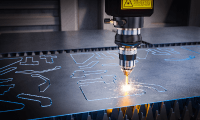
An Air Plasma Cutting Machine is a machine that uses high-temperature arc plasma to cut metals.

Because it is a type of plasma cutting machine and uses high-temperature arc plasma, it can cut metals efficiently. Compared to gas cutting machines and plasma cutting machines, they can cut many types of metals, including hard metals such as stainless steel, aluminum, brass, and iron.

They are also widely used in large factories, automobile repair shops, and shipyards. When metals need to be cut, Air Plasma Cutting Machines are essential in many industries because of their high efficiency.

Like plasma cutting machines, they require advanced technology, but when operated correctly, they are efficient.

Safety must also be taken into consideration, and it is important to wear appropriate safety equipment such as safety glasses and gloves during operation.

Uses of Air Plasma Cutting Machine

Air Plasma Cutting Machines are primarily used for cutting metal, mainly in processing plants. Unlike Plasma Cutting Machines, Air Plasma Cutting Machines use high-pressure air and can cut many metals, including hard metals, aluminum, brass, and iron.

They are used for cutting steel frames and steel products, processing metals at construction sites, and cutting metals in automobile and ship repair shops. Additionally, they are widely used in a variety of fields, including pipelines, steel mills, and the aerospace industry.

Air Plasma Cutting Machines, like Plasma Cutting Machines, are used manually and are effective for cutting thick plates, although they are not suitable for finish cutting as the cut surface tends to be somewhat rough.

Principle of Air Plasma Cutting Machine

Air Plasma Cutting Machines are composed of a plasma arc that melts and cuts metal by means of high-temperature arc heat and plasma flow.

The plasma arc is generated by applying high-frequency electricity between the electrode at the tip of the torch and the object to be cut. The electrode at the tip of the torch is heated by the electricity flow, and the surrounding air molecules are ionized and become plasma.

The plasma arc is maintained by the plasmaized gas and becomes extremely hot (approx. 20,000°C). This high-temperature plasma arc melts the metal, which is then blown away by high-pressure air for cutting.

Air Plasma Cutting Machines are also available in a water injection type equipped with an internal cooling system. Since the area around the plasma arc becomes very hot, cooling water is injected to release the heat, thereby extending the life of the torch.

The water injection type also has the advantage of improving cutting accuracy because the heating caused by the plasma arc is reduced.

Other Information on Air Plasma Cutting Machine

Advantages of Air Plasma Cutting Machine

Air Plasma Cutting Machines have the following four advantages: it can cut plates up to 100 mm thick, can cut materials that cannot be cut by gas cutting such as stainless steel and aluminum alloy, can cut curves with relative ease, has low running costs, is simple to operate, and is safe.

The advantages are as follows:

1. High precision cutting
Since plasma arc is used, the material is melted by heat and no residual stress is generated on the cut surface. Therefore, the cut surface is smooth and clean. Cutting can also be performed using a CNC machine, which enables high-precision cutting processing.

2. Energy saving
The material melted by the heat generated by the plasma arc is discharged at high speed. This reduces power consumption and saves energy.

3. High flexibility
During cutting, the quality of the cut surface can be changed by feeding cleaner gas between the torch and the object to be cut. This allows appropriate cutting conditions to be set when cutting sheet metal of different materials and thicknesses.

4. Low-cost introduction
Compared to other cutting technologies, the cost of equipment is low, making it possible to introduce the system at a low cost. Also, the consumables used are inexpensive, so running costs can be kept low.

カテゴリー
category_usa

Ground Terminal

What Is a Ground Terminal?

アース端子

A ground terminal (earth terminal) is a terminal for connecting a ground wire (grounding wire). Grounding is the connection of electrical equipment, the housing of electrical equipment, the neutral point of a line, or the reference potential wiring of electronic equipment to a reference potential point by means of an electrical conductor. It is generally connected to the earth (ground) as a reference.

Uses of Ground Terminals

The intended use of ground terminals is for connection to the grounding wire of electrical equipment and electrical and electronic equipment. The purposes of grounding are safety grounding, functional grounding, and lightning protection grounding. Ground terminals are installed for these purposes on the frames of electrical equipment and electrical/electronic equipment and inside the enclosures that house the equipment, and are used to connect the grounding wire.

*The terms “grounding” and “earth” are expressed as synonyms.

1. Safety Grounding

Safety grounding is a grounding method to prevent electric shock and fire accidents in electrical equipment. It prevents electric shock and fire due to heat generation when leakage current escapes through the ground wire and is touched by a person. For example, in general households, equipment such as washing machines, refrigerators, and microwave ovens are often used with liquids, which may cause a risk of electric leakage, so it is necessary to connect them to the ground terminals.

2. Functional Grounding

Functional grounding is used to stabilize the operation of electrical equipment and the communication of electrical and electronic equipment. Electronic equipment may malfunction due to the influence of electromagnetic waves and various noises from the surroundings. To prevent malfunctions, cover the electronic equipment with a shield and connect the shield to the ground terminals.

As an example, devices that use inverters and other devices that generate harmonics in their control circuits may be charged and emit them into the metal enclosure, causing the device to malfunction. Prevent charging by passing a ground current from the ground terminals to the earth.

3. Other Grounding

Other types of grounding include lightning protective grounding, static protection grounding, and temporary work grounding. Lightning protective grounding conducts lightning current caused by lightning strikes from the ground terminals to the ground wire. Anti-static grounding conducts the current charged by static electricity from the ground terminals to the ground wire. This prevents adverse effects on electrical and electronic equipment, etc.

Principle of Ground Terminals

The electrical connection to the earth having a stable potential is called grounding (earth). The electrical charge that flows out due to leakage of electricity is released through grounding to prevent the main body of electronic equipment from being adversely affected. Electrical circuits in electrical facilities and equipment for industrial applications are grounded.

By grounding the neutral point provided in these circuits (neutral point grounding method), it is possible to prevent power from flowing directly from the high-voltage side to the low-voltage side, even if the high-voltage and low-voltage sides are intermingled. Without grounding, there is a risk of high voltage being transmitted through the wires and damaging electronic equipment.

The neutral grounding method protects the power transmission system by preventing the occurrence of abnormal voltages in the event of arcing and the event of a single line ground fault. Thus, grounding plays an extremely important role in protecting power transmission systems, industrial electrical facilities, and electrical and electronic equipment.

Types of Ground Terminals

There are two types of ground terminals: screw type and one-touch type.

1. Screw-Type Ground Terminals

2766_Ground-Terminals_アース端子-1.png

Figure 1. Screw-type ground terminal

Screw-type ground terminals are used to secure a ground wire with a ring or Y-shaped crimp terminal attached to its end with a bolt on the terminal. For home appliances, the ground wire is stripped to the required length, clamped between washers at the bottom of the bolt, and secured by tightening a screw.

2766_Ground-Terminals_アース端子-2.png

Figure 2. Example of screw-type ground terminal use

2. One-Touch Ground Terminals

2766_Ground-Terminals_アース端子-3.png

Figure 3. One-touch ground terminal (Clip-on)

In the one-touch ground terminals, a ground wire with a crimp terminal attached to its end, or a stripped ground wire, is inserted into the terminal and secured with a one-touch clamp mechanism.

2766_Ground-Terminals_アース端子-4.png

Figure 4. Outlet with ground terminal (One-touch type)

The ground terminal outlet used in homes and buildings is another type of one-touch ground terminal. When the cover of the ground terminals part is opened, there is a terminal hole for inserting a ground wire, and the conductive part of the ground wire is fixed by removing the covering from the tip of the ground wire and inserting the conductive part.

Other Information on Ground Terminals

Size of Ground Terminals

In the case of a distribution board, the size of the ground terminals is determined by the size of the rated current (A) and the thickness of the ground wire.

Note: The size of the terminal for connecting the external protective conductor (PE terminal) is to be determined by the following procedure.

  • Determine the cross-sectional area of the external protective conductor from the cross-sectional area of the phase conductor of the power supply.
  • From the determined cross-sectional area of the external protective conductor, determine the size of the PE terminal to connect this protective conductor.

Select the appropriate ground terminal size from each manufacturer’s product catalog, etc., based on the external protective conductor sizes in the table above.

Crimp terminals and ground terminals are different. A crimp terminal is one of the connection terminals that is attached to the conductive end of an electric wire and can be fixed or crimped by applying mechanical pressure to the terminal and the wire.

カテゴリー
category_usa

RDX

What Is RDX?

RDX (Removable Disk Exchange) is a data backup system that uses removable disks.

RDX combines the advantages of both tape and disk-based systems. It is small and lightweight, yet extremely robust and resistant to physical shock, even when dropped from a height of one meter.

Data can be transferred by inserting the RDX cartridge into a dedicated drive and connecting it to a computer with a USB cable. This makes it similar to an external disk.

Furthermore, RDX can be carried offline or stored externally, thus serving to protect important data from computer virus attacks via the network.

Uses of RDX

The primary use of RDX is for system and data backup for small businesses and SOHOs (Small Office, Home Office). In many cases, small businesses and sole proprietors do not have engineers with specialized knowledge, and tape backup is difficult to handle.

RDX is relatively easy to handle, so even those without specialized knowledge can back up their important data to a sturdy RDX cartridge. RDX is also useful for data migration and transfer.

For example, if you are migrating data from an obsolete system to a new system, RDX can be used to capture the data. RDX is also used to consolidate data that is stored in many different locations.

In addition, RDX is suitable for off-site data storage. By storing data on RDX cartridges and moving them to an off-site storage location, data can be protected from risks such as natural disasters and data leaks.

Principle of RDX

RDX consists of a drive with a SATA or USB 3.0 interface and a removable cartridge. The cartridge contains a hard disk drive or SSD and is equipped with a buffer to absorb physical shocks.

System and data can be backed up by copying them to the hard disk drive or SSD inside the cartridge. After backup, the cartridge can be removed and stored in a safe place to protect against computer virus attacks.

In addition, multiple cartridges can be used to back up large sized data.

Types of RDX

1. External RDX Stand-Alone Drive

It has a USB 3.0 interface and allows insertion of a single RDX cartridge. It can be handled as an external disk by the computer and can be used with a variety of backup software. 

2. Internal RDX Stand-Alone Drive

It can be installed in a 5-inch bay or 5.25-inch bay of a computer. Two models exist for the connection interface: USB 3.0 and SATA. Can be handled as a normal internal disk. 

3. Rack-Mount Type

Multiple RDX cartridges can be installed at once in this rack-mountable type. It is connected to the computer via a 10Gb network. This product is mainly for servers.

Other Information About RDX

Data Backup Methods

There are two main types of methods for backing up computer data: tape-based and disk-based.

1. Tape type
The tape type has the advantage of durable cartridges and low cost, but it can only be accessed sequentially. As a result, arbitrary data cannot be retrieved and data transfer speeds are slow. Another drawback is that transferring data from tape to computer is cumbersome.

2. Disk type
The disk type is capable of random access and can retrieve arbitrary data. The advantage is that the data transfer speed is fast and the transfer procedure is simple, but the disadvantage is that it is vulnerable to shocks.

RDX backup compensates for these shortcomings by incorporating a small HDD (hard disk drive) in the RDX cartridge, which is covered with shock-absorbing material to protect the HDD from shocks.

RDX can be used just like an ordinary external HDD, and thus can compensate for the disk-type disadvantage of being vulnerable to shocks, while taking advantage of the advantages of HDDs.

カテゴリー
category_usa

UHF Receiver

What Is an UHF Receiver?

An UHF (Ultra High Frequency) Receiver is a device that receives ultra high frequency radio waves.

UHF Receivers catch this frequency band and convert it into a form that viewers and users can use to obtain information.

Note that the UHF band uses a higher frequency band than the VHF (Very High Frequency) band, resulting in faster communication speeds and greater data transfer capabilities. On the other hand, it is also susceptible to physical obstacles.

In general, few receivers receive only UHF signals, and most receivers are usually capable of receiving a wider bandwidth of signals.

Uses of UHF Receivers

UHF Receivers are widely used in professional audio equipment. Some of the major applications of UHF Receivers are listed below:

1. Wireless Microphones

UHF Receivers are used for wireless microphones. The receiver receives the signal transmitted from the microphone and converts it into an audio signal. There are many high-performance and compact UHF Receivers available, and they are used for various applications. 

2. Professional Audio Equipment

UHF Receivers can be used to receive high-quality audio signals from professional speakers, amplifiers, and mixers.

3. Karaoke Equipment

UHF Receivers are used to receive wireless microphones, which are often used in karaoke. The UHF Receiver can handle multiple channels and provides clear sound through digital processing. It also uses a front antenna for highly efficient reception, making it easy to move and install. 

4. Wideband Receiver

A wideband receiver is a receiver that covers many frequency bands. It can receive amateur radio, aviation radio, and various types of digital radio.

Principle of UHF Receivers

An UHF Receiver consists of the following four major parts:

1. Antenna

This is the part that receives radio waves in the UHF band. The shape and size of the antenna depends on the frequency you want to receive. Radio waves received from the antenna are converted into electrical signals. 

2.Tuner

The tuner is the part that selects the desired frequency from the radio waves converted into electrical signals. The tuner uses elements such as variable capacitors and variable inductors to adjust the frequency.

The signal output from the tuner is converted to a fixed frequency called the intermediate frequency (IF).

3. Demodulator

The demodulator is the part that extracts information such as audio and video from the signal converted to the intermediate frequency. The demodulator demodulates the signal using different circuits depending on the modulation method.

The signal output from the demodulator is sent to speakers, displays, etc.

4. Control Circuit

This is the part that controls the operation of the UHF Receiver. The control circuit uses integrated circuits such as microcontrollers and microprocessors to perform operations such as channel selection and volume adjustment. The control circuit receives inputs from remote controls and buttons.

Types of UHF Receivers

UHF Receivers can be divided into the following types according to their various applications and performance.

1. Receivers for Wireless Microphones

These Receivers receive audio signals transmitted from wireless microphones for karaoke and live performances. Usually, the 800 MHz or 900 MHz band is used to transmit signals using FM (frequency modulation) or digital modulation methods.

They are required to have excellent reception sensitivity, distortion, and sound quality. Depending on the model, some UHF Wireless Receivers offer clear sound quality through digital processing and use a front antenna with high-efficiency reception, making them easy to move and install.

2. Handy Receiver

These small, portable receivers cover a wide frequency band and can switch between FM, WFM (wideband FM), AM (amplitude modulation), and other reception modes. It can receive radio broadcasts, air bands, and various types of commercial radio.

They should have excellent battery life, scanning speed, and memory functions. Some models cover 0.100 to 1309.995 MHz, and there are wideband handy receivers with various functions such as high-speed scanning of 100 channels/second and blank line canceller.

3. Receiver System

A receiver system works with multiple transmitters and antennas to receive high-quality audio and video. They are used in conference rooms, classrooms, theaters, etc. They are required to have excellent simultaneous channel count, frequency stability, and interference rejection capability.

カテゴリー
category_usa

Millimeter Wave Radar


What Is Millimeter Wave Radar?

Millimeter Wave RadarsMillimeter wave radar is a radar that uses millimeter wave (wavelength: 1 mm to 10 mm/frequency: 30 GHz to 300 GHz) radio waves to detect the distance, location information, and relative speed of an object.

In general, sensors that detect distance include LiDAR, ultrasonic waves, and stereo cameras, in addition to millimeter wave radar. The advantage of millimeter wave radar is that it can detect distances of 150 meters or more. It is not affected by sunlight, rain or fog, etc. The disadvantage is that it is difficult to detect objects with low radio wave reflectivity, such as cardboard and Styrofoam.

Uses of Millimeter Wave Radar

Millimeter wave radar is used in automobiles, industrial machinery, and drones. In particular, it is often used in automobiles as a safety device.

ADAS (advanced driver-assistance system) is a safety device that is currently widely used in automobiles. 76GHz millimeter wave radar is used for adaptive cruise control and collision mitigation braking to detect the road ahead. The ADAS functions, such as adaptive cruise control and collision mitigation braking, use 76 GHz millimeter wave radar to detect the road ahead. For higher resolution and improved accuracy, the 79 GHz band will be shifted to the future.

In addition, blind spot monitors use the 24 GHz band. Millimeter wave radar will be used even more as automated vehicles are developed in earnest.

Principle of Millimeter Wave Radar

The main components of millimeter wave radar are a synthesizer that processes the transmitted radio waves, a Tx antenna that transmits the radio waves, an Rx antenna that receives the reflected radio waves, and a CPU that processes the received signals.

The principle of millimeter wave radar is that the Tx antenna transmits radio waves processed by the synthesizer from the radar, the Rx antenna receives the reflected radio waves from the object, and the CPU processes the signals to measure distance and other parameters.

There are two main methods of measuring distance and velocity: pulse and FMCW. Angle is mainly measured by the electronic scan method.

1. Pulse Method

The distance is calculated from the time it takes for the reflected radio wave to return from the object.

2. FMCW Method

This method transmits radio waves of varying frequency over time and calculates the distance from the beat frequency (frequency difference) generated by interference between the transmitted signal and the signal reflected from the object.

3. Electronic Scanning Method

This method uses multiple Rx antennas and detects the phase difference between each antenna. The angle of the object to be measured can be calculated from the phase difference.

Other Information on Millimeter Wave Radar

1. Accuracy of Millimeter Wave Radar

Millimeter wave radar can detect obstacles and objects in the vicinity with high accuracy because it diffuses short wavelengths into the surrounding area. It has a high resolution and can detect the shape of an object and how it has moved (or changed) to the nearest 0.1 mm.

It also has an advantage over infrared lasers and ultrasonic lasers in terms of the distance over which objects can be detected. While infrared lasers and ultrasonic lasers can detect objects at a distance of about 20 meters and ultrasonic lasers can detect objects at a distance of about 1 meter, millimeter wave radar can detect objects at a distance of 150 meters.

Millimeter wave radar can maintain high accuracy even in adverse environments. While infrared and ultrasonic lasers show variations in accuracy due to changes in ambient temperature and other factors, millimeter wave radar is a radio wave sensor, which is highly linear and stable in detecting objects, regardless of the environment.

2. Interference by Millimeter Wave Radar

In the future, when automated driving becomes widespread, millimeter wave radar will be used more frequently in high-density environments, and there is a concern about radio interference between radars.

Radio interference could interfere with target detection by millimeter wave radar and lead to false positives, which could result in serious traffic accidents. In order for millimeter wave radar to achieve high range resolution, it must use the entire 3-4 GHz frequency range allocated to radar for each vehicle. It is essential to develop technologies to avoid this.

3. Weaknesses of Millimeter Wave Radar

As mentioned earlier, millimeter wave radar can easily and stably range an object even in adverse environments, but there are some objects that it is not good at detecting.

On the other hand, some objects are difficult to detect. These are relatively small objects and objects with low reflectivity to radio waves, such as cardboard boxes. In terms of distance to objects, millimeter-wave radar is good at detecting objects at long distances, but it is also poor at detecting objects at short distances.

4. Future Trends in Millimeter Wave Radar Technology

Until now, LiDAR (light detection and ranging), with its superior recognition resolution, has played a leading role as a sensor required for automated driving, but innovations in radar technology are enabling it to draw recognition resolution close to that of LiDAR. The keywords driving this technology are advances in semiconductor microfabrication technology, frequency bandwidth expansion, and antenna technology such as beamforming.

Advances in Semiconductor Microfabrication Technology
Advances in CMOS miniaturization technology not only enable the use of smaller and less expensive millimeter-wave signal processing ICs. Digital beamforming technology, which uses the ultimate analog technology of high-frequency circuits in the millimeter wave band and digital technology to achieve highly efficient beam forming, is currently being actively developed by a variety of companies and research institutes.

Expansion of Frequency Bandwidth
The most important factor is to secure the recent 5 GHz bandwidth from 76 GHz to 81 GHz. The increase in frequency bandwidth will directly contribute to the expansion of the radar range. In the near future, it is said that a continuous 12.5 GHz bandwidth between 136 GHz and 148.5 GHz in the D-band will be available for radar, making millimeter wave radar technology increasingly important.

Evolution of Antenna Technology
Advances in antenna technology, particularly array antenna technology, and ultra-compact, low-loss array antenna integrated module technology, are important. This will enable millimeter wave radar to achieve higher power and efficiency.

カテゴリー
category_es

Medidores de Corriente de Fuga

¿Qué es un Medidor de Corriente de Fuga?

Medidores-de-Corriente-de-FugaUn medidor de corriente de fuga es un instrumento para medir la corriente de fuga de los equipos eléctricos.

Generalmente se refiere a una pinza amperimétrica que puede medir corrientes diminutas de mA o menos.

Usos de los Medidores de Corriente de Fuga

Los medidores de corriente de fuga se utilizan generalmente en instalaciones eléctricas y equipos médicos con el fin de determinar el cumplimiento de las normas legales.

Las corrientes de fuga tienen un impacto significativo en el cuerpo humano, e incluso una corriente de fuga muy débil puede conducir directamente a la muerte, por lo que una medición precisa es necesaria desde el punto de vista de la seguridad. También es importante desde el punto de vista de la calidad, ya que puede provocar ruido en los equipos de comunicación.

Principio de los Medidores de Corriente de Fuga

Los medidores de corriente de fuga no tienen contacto con el conductor del circuito y miden la corriente sujetando un cable de cobre entre ellos con una pinza amperimétrica.

El principio de la detección de corriente es detectar el campo magnético generado por la corriente y extraer una salida proporcional a la corriente medida. Los métodos de detección más comunes incluyen el método CT, el método de la bobina de Rogowski, el método del elemento Hall y el método fluxgate.

1. Método CT

Este método convierte la corriente a medir en una corriente secundaria correspondiente a la relación de vueltas.

2. Método de la Bobina de Rogowski

Este método convierte la tensión inducida en una bobina con núcleo de aire por un campo magnético alterno creado alrededor de la corriente que se desea medir.

3. Método del Elemento Hall

Este método combina los métodos del elemento Hall y del TC para medir a partir de la corriente continua. Un elemento Hall es un elemento que mide la tensión generada cuando una corriente fluye a través de un punto en el que se genera un campo magnético, y este método es el pilar de la medición de CC.

4. Método Fluxgate

Este método combina los métodos fluxgate (elemento FG) y CT para medir a partir de corriente continua. El fluxgate es un elemento que mide el campo magnético generado por el bobinado de dos bobinas opuestas alrededor de un núcleo de hierro, y calcula el valor de la corriente hacia atrás a partir del campo magnético.

Más Información sobre los Medidores de Corriente de Fuga

1. Corriente de Fuga y Productos Sanitarios

Los dispositivos médicos requieren la aprobación del Ministerio de Sanidad, Trabajo y Bienestar antes de poder comercializarse. La aprobación de los dispositivos médicos eléctricos, que se conocen como dispositivos médicos activos, debe especificar la categoría en la que se encuadra eléctricamente el accesorio (donde el dispositivo se conecta al paciente).

En concreto, los productos sanitarios utilizados en los entornos más severos, como el corazón, deben ajustarse a la categoría de “accesorio tipo CF” (límite de tolerancia de corriente de fuga 0,01 mA), tal y como se define en la norma IEC 60601-1. Por lo tanto, el control estricto de la corriente de fuga que se escapa del dispositivo es importante durante la fase de verificación del diseño de los dispositivos médicos. Por lo tanto, en la aprobación de dispositivos médicos, la corriente de fuga se mide utilizando un medidor de corriente de fuga dedicado (dispositivo de prueba) correspondiente a la norma.

2. Diferencias entre los Medidores de Corriente de Fuga y los Amperímetros Generales

La principal característica de los medidores de corriente de fuga es su resolución. Los amperímetros que miden las corrientes de carga miden grandes corrientes de 1 A o más para los sistemas de sujeción. Los medidores de corriente de fuga, por el contrario, necesitan medir corrientes débiles y, por lo tanto, pueden medir corrientes débiles de 1 A o menos. También existen amperímetros de carga que miden corrientes débiles para procesos de fabricación de semiconductores, pero para estas aplicaciones, los dispositivos suelen estar conectados en serie al circuito.

3. Cómo utilizar los Medidores de Corriente de Fuga

Los medidores de corriente de fuga de tipo pinza se utilizan para las pruebas de corriente de fuga del cableado eléctrico y pueden probar el equipo mientras está energizado, sin necesidad de un corte de energía.

Preparación del Entorno de Medición
Debido a su principio, los medidores de corriente de fuga se ven afectados por campos magnéticos externos. Por lo tanto, la medición debe realizarse en un lugar aislado de equipos que puedan causar campos magnéticos externos, como transformadores.

Método de Medición
Abra la pinza anular, introduzca el cable a medir en la anilla y cierre la pinza. Para mediciones de corriente de fuga con fase cero, pinzar todas las fases juntas. Para medir la corriente de fuga debida a los cables de tierra, sujete sólo el cable de tierra. A continuación, se ajusta el intervalo de medida en función del objetivo de la medición y se inicia la medición. Algunos productos permiten ajustar el intervalo de visualización, mientras que otros pueden mostrar valores medios. Es importante seleccionar un medidor de corriente de fuga de acuerdo con el objeto y la finalidad de la medición.

4. Tipo de Corriente de Fuga

Corriente del Conductor de Protección (Corriente de Fuga a Tierra)
Definida en la norma IEC 60601-1 como “corriente que fluye desde el componente de red a través o a través de un aislante hasta el conductor de tierra de protección o la línea de conexión a tierra funcional”.

Corriente de Contacto o Corriente de Fuga del Recinto
Definida en la norma IEC 60990 como “la corriente que atraviesa el cuerpo humano o animal al tocar una o varias partes accesibles de la instalación o el equipo”.

Corriente de Fuga del Paciente
Definida en la norma IEC 60601-1 como “corriente que fluye desde la conexión del paciente a tierra a través del paciente”.

Corriente Medida por el Paciente (Sólo Equipos Eléctricos Médicos)
Definida en la norma IEC 60601-1 como “corriente no destinada a tener un efecto fisiológico que fluye entre una conexión de paciente y cualquier otra conexión de paciente a través del paciente durante el uso normal”.