カテゴリー
category_usa

Electronic Counter

What Is an Electronic Counter?

An electronic counter is a device that utilizes electronic circuits or sensors to automatically count occurrences or objects. Compared to electromagnetic counters, they offer faster and more accurate measurements but require a power source for their digital components. These counters are broadly categorized into electronic total counters, which display cumulative counts, and electronic preset counters, which signal upon reaching a pre-defined count.

Uses of Electronic Counters

Electronic counters find applications across various fields for both quantitative control and precise feedback mechanisms. They are instrumental in manufacturing for product tallying, parking lot management for space tracking, and retail for inventory management. Additionally, they play a crucial role in traffic management systems, event attendance tracking, and in combination with a rotary encoder or photoelectric sensor for precise control of machinery based on specific measurements.

Principle of Electronic Counters

The core of an electronic counter is a digital circuit that counts pulses and typically includes flip-flop circuits for binary counting. To make the binary count understandable, most counters feature an LED display that presents the count in decimal form. Preset counters also have a functionality to compare the count with a preset number and generate a specified output. These devices generally rely on batteries or external power sources for operation.

How to Select an Electronic Counter

  • Suitability for the Application: Determine the specific needs and operational environment to narrow down the options.
  • Accuracy and Reliability: Opt for counters known for precise measurements and consistent performance, considering both manufacturer reputation and user reviews.
  • Interface and Data Management: Choose counters with user-friendly data handling capabilities, considering the need for connectivity options like USB, Wi-Fi, or Bluetooth for efficient data management.
  • Budget and Cost: Balance between cost and required functionalities, ensuring the selected counter meets your accuracy needs within budget constraints.

Electronic counters are a vital tool in automating and optimizing data collection and analysis across various applications, from industrial manufacturing to public event management.
カテゴリー
category_usa

Electronic Scale

What Is an Electronic Scale?

Electronic Scales

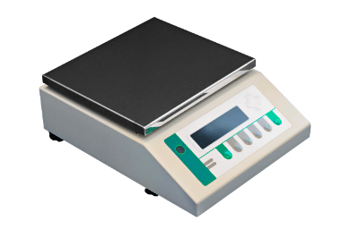
An electronic scale is a weighing instrument used to measure the mass of an object.

The two most common types of electronic scales in general use are the electromagnetic force balance type (electromagnetic type) and the load cell type. Electromagnetic electronic scales use electromagnetic force instead of weights in balances and are characterized by their ability to perform highly accurate measurements. On the other hand, they tend to have complex structures and are difficult to miniaturize.

Load cell electronic scales use electrical resistance instead of electromagnetic force to perform measurements. Since the structure is simpler than that of the electromagnetic force balancing type, it is relatively easy to manufacture large products. On the other hand, they tend to be inferior to the balanced electromagnetic force type in terms of accuracy.

Principles and Uses of Electronic Scales

There are various types of electronic scales with different measurement principles. As mentioned above, the two main types are the electromagnetic balance type and the load cell type.

The electromagnetic force balance type uses electromagnetic force to balance a sample in a receiving pan as a substitute for a weight to measure its weight. A downward force is applied by passing an electric current through a force coil. The balancing is controlled by controlling the current value of the force coil while checking the balancing position with a light source and position sensor. The weight is read by reading the current value at this time.

As mentioned above, the electromagnetic force balancing type electronic scales excel in high-precision measurement. For this reason, they are used in analytical electronic scales (electronic balances) designed for experiments that require high precision. However, it is important to perform calibration as necessary for accurate measurements.

Structure of Electronic Scales

The load cell method reads the weight from the deflection of a strain gauge made of aluminum or other material. Strain gauges attached to the strain body expand and contract, resulting in a change in electrical resistance. The weight is measured by reading this change in resistance as an electrical signal.

Load cell electronic scales are characterized by their simple structure. They are used in large electronic scales such as weight scales and are also used in small scales when cost reduction is desired. 

How to Select an Electronic Scale

When selecting an electronic scale, it is necessary to select an appropriate one according to the characteristics of the sample to be measured, the purpose of use, etc. Basically, the size of the weighing pan, weighing capacity, and minimum display should be selected.

First of all, the scale must have a pan that matches the size of the sample to be measured.

The weighing capacity is the maximum amount that the scale can accurately measure. The weight of the object to be measured must be within the scale weight.

The minimum indication is the smallest value that the instrument can indicate in a measurement and should be selected according to how closely the object to be measured is measured. It is important to note that the minimum indication is only the smallest value that can be displayed and does not mean that the sample can be accurately measured to that value. The smallest weight for which an object can be measured accurately is the minimum weighing value, which is the smallest size for which twice the standard deviation of repeated measurements falls within 0.10% with a probability of 95.4%.

If measurement accuracy is important, attention should also be paid to the linearity and repeatability of the instrument. The higher the measurement accuracy, the more expensive the scale will be. Therefore, it is important to select an appropriate scale according to the accuracy you wish to measure.

カテゴリー
category_usa

Electron Beam (EB) Welding Service

What Is an Electron Beam (EB) Welding Service?

An EB welding service is a welding process in which electrons emitted from an electron tube are accelerated using magnetic and electric fields to heat and melt a workpiece.
The cathode of the electron tube emits hot electrons when heated. This emission phenomenon is based on the same principle as that used in cathode-ray tubes.

The process of heating and melting by irradiating the workpiece with these hot electrons is basically performed in a vacuum.
The workpiece can be processed from thick to thin plates, and the welded area is characterized by the fact that distortion is unlikely to remain.

Recently, welding methods that can be performed in a low-vacuum environment and electron gun transfer type that emits electrons are also used.

Uses of EB Welding Services

A number of applications for EB welding services has been proposed for different materials.

  1. Materials that are difficult to weld using other welding methods
    Dissimilar metal materials such as stainless steel and iron, stainless steel and copper, etc.
  2. Hermetically sealed welded parts
    Large structures such as pressure tanks and vacuum chambers, and cooling parts such as water-cooled jackets.
  3. Parts for low distortion welding and high speed welding.
    Automobile parts such as gears.
  4. Materials that prevent oxidation of the workpiece surface during welding.
    Active metal materials such as titanium and niobium.
  5. Parts compatible with keyhole welding (deep penetration welding), thin weld bead (weld metal), and low distortion welding.
    Metal materials with high thermal conductivity such as copper and aluminum.

Principle of EB Welding Services

When a cathode filament is heated in a vacuum, electrons are continuously emitted. The electrons produced here are called heat electrons.
The emitted electrons are accelerated by the high voltage (60 to 150KV) applied between the cathode and anode to form an electron beam.

This electron beam is focused by an electromagnetic coil and further controlled in the scanning direction by a deflecting coil to concentrate irradiation on a specific spot on the surface of the target workpiece.

The kinetic energy of the hot electrons impacting the workpiece is then converted into thermal energy, and the surface of the workpiece becomes so hot that it melts, completing the welding process.

The spot diameter of the EB welding services normally used is very small, approximately 0.2 mm, and the thermal effect applied to the periphery of the weld is minimal, so welding can be performed with little distortion remaining on the surface or inside of the metal.

By adjusting the output of the EB welding services, the range and depth of metal penetration can be controlled, enabling welding of a wide range of plate thickness materials, from thin to thick plates.

カテゴリー
category_usa

Electromagnetic Clutch

What Is an Electromagnetic Clutch?

Electromagnetic Clutches

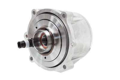
An electromagnetic clutch is a machine that uses electromagnetic force generated in a coil to connect two shafts and transmit power, or to disconnect two shafts and shut off power.

Since power transmission can be easily controlled by energizing the coil, not only can it be operated remotely, but it can also transmit power intermittently.

An electromagnetic clutch is classified into friction type, meshing type, pneumatic clutch type, and spring type, depending on the method of torque generation.

Of these, the friction type is the most commonly used because of its simple structure, low cost, and excellent controllability.

Uses of Electromagnetic Clutches

Electromagnetic clutches are used as machines that transmit the rotational power of engines, generators for automotive equipment, and driving power for hydraulic pumps.

Clutches can be mechanical, hydraulic, or electromagnetic, depending on their operating principle. However, electromagnetic clutches are commonly used in industrial applications. This is due to the fact that power transmission between shafts can be easily controlled by electromagnetic force.

In addition to automotive equipment, small electromagnetic clutches are used for torque transmission in office equipment and communication devices.

Principle of Electromagnetic Clutches

In addition to electromagnetic clutches, there are mechanical clutches and hydraulic clutches, depending on the actuation method.

Electromagnetic clutches are commonly used because they are easily controlled by electromagnetic force.

Electromagnetic clutches are classified into various types according to the torque generation method.

  • Intermeshing clutch
    A clutch engages the jaws of the driven shaft and the prime mover shaft to connect or disconnect the two shafts.

    Since engaging the claws during rotation generates a shock, the claws are joined during low-speed operation.

  • Friction clutch
    A friction clutch transmits power by frictional force through contact between friction plates attached to the driving and driven shafts.

    Since the strength of the friction plates can be varied, smooth joints with minimal impact can be achieved even while the shaft is rotating.

  • Automatic clutch 
    Automatic clutches automatically transmit or shut off power when the rotation of a shaft exceeds certain conditions. As a result, power can be transmitted through the friction surfaces.
カテゴリー
category_usa

Electromagnetic Chuck

What Is an Electromagnetic Chuck?

Electromagnetic Chucks

An electromagnetic chuck is a device that uses an electromagnet to clamp workpieces in machine tools.

Requiring an external power supply for operation, electromagnetic chucks generate heat when energized. They are best suited for machining large materials where high precision is not the primary concern. Their size can be easily adjusted to accommodate a wide range of material sizes.

The chucking force is adjustable via an external switch, simplifying the automation of the chucking process alongside machinery. A variant, the permanent electromagnetic chuck, utilizes a magnet that is energized only during attachment and detachment, conserving energy when not in use.

Applications of Electromagnetic Chucks

Electromagnetic chucks are integral to various machine tools, including milling machines, drilling machines, grinding machines, and more. They are invaluable for securely holding workpieces during both cutting and non-cutting processes, such as electrical discharge machining. Their ability to switch the magnetic force on and off facilitates easy handling of ferrous work materials.

Principle of Electromagnetic Chucks

1. General Electromagnetic Chuck

This type of chuck consists of an iron core and a coil, with a faceplate designed to prevent ingress of water. Energizing the electromagnet generates magnetic field lines that attract and hold the workpiece firmly. De-energizing the electromagnet releases the workpiece instantly.

2. Permanent Electromagnetic Chuck

Employing a permanent magnet, this chuck type is energized only during the attachment and detachment of materials, maintaining magnetic force without continuous power, thus being energy efficient. It features rod-shaped electrodes and brass separators for pulse voltage application, enabling high-precision machining without thermal displacement.

Features of Electromagnetic Chucks

1. Easy Attachment and Removal of Workpiece

The ability to switch the electromagnet on and off simplifies the process of attaching and detaching workpieces, facilitating automation.

2. Adjustable Suction Force

The chuck’s suction force is adjustable, making it versatile for different types and intensities of machining.

3. Easy to Enlarge Chuck Size

Electromagnetic chucks can be easily scaled up, with models available that offer clamping forces around 300 kg.

Types of Electromagnetic Chucks

Electromagnetic chucks come in round and square shapes, catering to various work materials and machining processes. They can be categorized by cooling method: non-cooled, water-cooled, and air-cooled, with cooling essential for maintaining workpiece temperature and machining accuracy. Tiltable models allow for precise angle adjustments, crucial for grinding mold parts, featuring high-precision components and temperature control to ensure accuracy.

The permanent electromagnetic chuck combines permanent magnets and electromagnets for energy-efficient operation during attachment and detachment processes.

カテゴリー
category_usa

Electromagnetic Brake

What Is an Electromagnetic Brake?

Electromagnetic Brakes

An electromagnetic brake is a device that applies a brake using electromagnetic force.

An electromagnetic brake is designed to apply the brakes in the event of power loss. Therefore, they are used when it is necessary to apply the brakes on the spur of the moment. They are primarily used in industrial applications and are not commonly found in homes.

Since electromagnets are used, electricity is used as the power source. As it is more cost-effective to use the same power source, they are mostly used to stop motors that are driven by the same electricity.

Uses of Electromagnetic Brakes

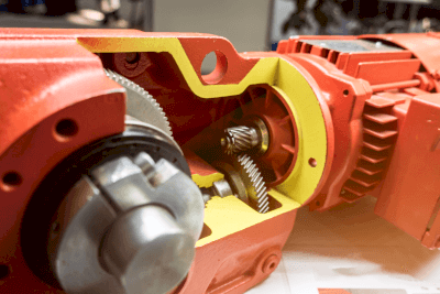
Electromagnetic brakes are almost never used in automobiles. They are basically used in motors with reduction gears.

A typical example is the hoisting equipment of a crane. If the brake is not applied when power is lost, the suspended load will fall, which is very dangerous. Therefore, electromagnetic brakes are used in crane hoisting equipment to stop the suspended load in an emergency.

Electromagnetic brakes are also sometimes used on conveyor belts and other equipment to prevent inertia-induced movement of workpieces when stopped.

Principle of Electromagnetic Brakes

Electromagnetic brakes are mainly divided into three parts: the electromagnet part, the rotor part, and the brake part.

The electromagnet part is responsible for the electrical circuit that controls the operation of the electromagnetic brakes. A coil wound around an iron core generates a magnetic field like a magnet when electricity is applied to the coil. This is called an electromagnet. The electromagnets in electromagnetic brakes attract the rotor by magnetic force, thereby controlling the motion of the brake.

The rotor part moves in the same way as the rotating shaft. When the brake is not applied, the rotor rotates in the same manner as the rotating shaft, and when the brake is applied, it makes contact with the brake by spring force. Friction between the brake and the rotor causes the rotating body to come to a sudden standstill, thereby applying the brake.

The brake part refers to the contact surface that brings the rotor to a standstill. It is called a brake shoe or armchair. If the rotor is kept stationary continuously or rotated while rubbing against the rotor, it will heat up due to friction, causing failure such as burning out of the brake portion. Therefore, it is essential to adjust the distance to the rotor and the degree of contact.

カテゴリー
category_usa

Electric Winch

What Is an Electric Winch?

Electric Winches

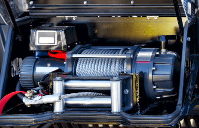
An electric winch is a general term for a winch that pulls an object by winding up a rope or wire with an electric drum. A manual winch operates on the same principle but is operated manually.

An electric winch is used for lifting and lowering heavy objects, as well as for pulling up cars and ships. The principle is the same as that of hoists, etc., but hoists can move horizontally, while an electric winch is fixed.

There are different sizes depending on the application, ranging from small portable winches to large stationary winches.

Uses of Electric Winches

As mentioned above, electric winches are used for lifting and lowering heavy objects, vehicles, and vessels. Installing electric winches above work sites to raise and lower heavy objects improves work efficiency and facilitates smooth operation. It also reduces the risk of accidents that can occur when lifting by hand.

Electric winches can be attached to a truck to recover a vehicle that has gone off the road and fallen down a cliff. They can also be used to bring a vessel to shore by attaching a hook to both the vessel and the shore and hoisting it up.

Principle of Electric Winches

The principle of operation of electric winches is that the drum is rotated by a motor (electricity) and a rope or wire is wound around it to pull an object. The motor attached to an electric winch is small, and the output of the motor by itself is small. By slowing down the motor through a speed reducer and increasing the torque, the output can be increased several times, making it possible to pull heavy objects. A hook is attached to the end of the wire, which is hooked onto the object to be pulled. The type with a hook on the main body is used by hooking the hook on the side to be fixed. The type that is fixed to the beam instead of hooks is fixed to the beam with bolts, nuts, etc.

The electric winches to be used are selected according to the weight of the object to be pulled. It is important to check the specifications of various components, such as the output (kW) of the motor, the material and thickness of the rope and wire used, and the load capacity of the hook, before selecting the winch.

In the event of a sudden accident, the winch may be useful because it can be used in a confined space. If equipped on the back of a truck, it can be useful in an emergency.

カテゴリー
category_usa

Electric Lift

What Is an Electric Lift?

Electric Lifts

An electric lift is a work platform for loading and moving loads in situations requiring work at heights.

Even if the load is heavy, it can be raised and lowered stably and stopped immediately when necessary.

The speed of lifting and lowering can be controlled, and by lifting and lowering at a constant speed, efficient and regular motion can be achieved.

Compared to hydraulic lifts, electric lifts have the advantage of generating less noise during lifting and lowering, as well as eliminating the risk of oil leaks.

Uses for Electric Lifts

Electric lifts are used in a variety of workplaces that require lifting goods and people to and from high places.

In factories such as food, automobile plants, chemical plants, and household appliance plants, electric lifts can be integrated into production lines to adjust the height of goods as they are transported to and from the lift.

Electric lifts are also used in stage sets to adjust the position of tools according to their performance.

Other uses include the docking of parts when assembling robots.

Principle Uses of Electric Lifts

On factory production lines and other sites requiring work at heights, there are situations where lifting and lowering of loads is necessary.

The main types of equipment used to raise and lower heavy loads are electric lifts, hydraulic lifts, and electro-hydraulic lifts.

Electric lifts do not use oil as the driving force for lifting and lowering. Therefore, there is no oil leakage and no risk of spontaneous lowering. They also do not require oil changes.

Hydraulic lifts use hydraulic pressure to raise and lower loads by manually adjusting the lift height. They are suitable for lifting relatively light loads. The lift itself is easy to move and can be used even in small spaces. It also has the advantage of not requiring a power supply.

Electric hydraulic lifts have a hydraulic unit built into the main body, are highly durable, and are widely used for a variety of applications.

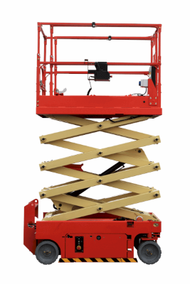
Most electric lifts use an X-shaped arm (scissor lift) to raise and lower the load in order to maintain the load’s installation surface horizontally.

The effect of this scissor lift prevents the lift from swaying sideways, allowing it to be raised and lowered safely.

カテゴリー
category_usa

Electric Tool

What Is an Electric Tool?

Electric Tools

An electric tool is a tool that is operated by electricity.

Tools such as eyeglass wrenches and screwdrivers are generally used by human power. An electric tool allows work to be done much faster than by human power. Some electric tools are capable of performing crafts with a greater force than human power.

However, they have the disadvantage of being more expensive than human-powered tools, and their drive units can break down. They are also heavier because they come with batteries and motors. They may not be able to be used in confined spaces because they are not maneuverable.

Uses of Electric Tools

Electric tools are widely used in production and construction sites. In regions where DIY activities are popular, such as the United States, even ordinary households have their own power tools.

In places with huge piping, such as process factories, the bolts used in flange sections are also huge, requiring a long time for manual fastening. Therefore, man-hours are reduced by using impact wrenches and other tools. Electric sanders are also sometimes used to remove rust and process metals.

On construction sites, they are used for cutting and processing wood and plasterboard. They are indispensable in today’s industry.

Principle of Electric Tools

As the name implies, electric tools are powered by electricity. Generally speaking, there are two types of power tools: those with cords for power supply and those that are battery-operated.

Globally, commercial power supplied by electric power companies is alternating current. Therefore, those with cords have a built-in motor for AC, which rotates inside to do the work. Bolts, screws, and similar fasteners come in various head sizes depending on the device’s requirements. Therefore, most electric fastening tools can easily accommodate different head sizes by changing attachments. There are also multi-functional products that can be used as a drill, screwdriver, wrench, etc. with a single product by changing attachments.

In recent years, the demand for electric tools that operate on batteries accounts for most of the demand due to the evolution of energy storage technology, represented by lithium-ion batteries. Since the power source is also DC low voltage, the risk of electric shock is reduced. Since the battery is a DC power source, it has a built-in DC motor. Battery-powered electric tools come with a charger with an AC adapter as an accessory.

カテゴリー
category_usa

Current-limiting Fuse

What Is a Current-Limiting Fuse?

Current Limiting Fuses

A current-limiting fuse is a type of safety device for electrical equipment.

When an accident occurs, such as a short circuit in an electrical circuit, an abnormally high current flows through the circuit, generating heat and possibly causing a fire. One method of avoiding this danger is to include a current-limiting fuse in the circuit.

When an abnormal current flows, the fuse element in the current-limiting fuse, a fusible metal element, heats up and melts, causing the circuit to open, thereby suppressing the abnormal current. The fused element is irreversible. Once a current-limiting fuse has served as a safety device, it must be replaced with a new fuse.

Uses of Current-Limiting Fuses

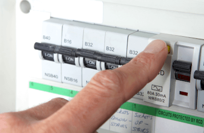
Since current-limiting fuses are safety devices against abnormal currents, they are used in a variety of applications, including home appliances, switchboards, and automobiles.

Especially in the automotive field, current-limiting fuses are in high demand as a safety device due to the increasing use of electronic components, such as engine control by microcomputers.

On the other hand, although current-limiting fuses have the advantage of being inexpensive to install, once the element blows, the user must replace it with a new fuse. For this reason, switch-type breakers are more common than current-limiting fuses. Especially as a safety device for interrupting abnormal currents in switchboards that need to be restored immediately after an overcurrent interruption.

Principle of Current-Limiting Fuses

Current-limiting fuses operate on the simple principle that when the current exceeds the rated value, the fuse’s element heats up, melts, and interrupts the circuit.

Since the thermal resistance of the element is higher at the center than at the ends, heat is conducted from the center to the ends. Under normal conditions, heat in the element escapes to both ends. However, if a current exceeding the rated current flows through the element, heat conduction cannot keep up, and the center of the element exceeds its melting temperature, causing it to shut down.

Current-limiting fuses not only interrupt the circuit when an abnormal current flows but must also pass the current during normal operation. Therefore, when selecting current-limiting fuses, consideration must be given to ensure that the steady-state current during normal operation is lower than the rated current.

In practice, the steady-state current must be less than the rated current plus a temperature derating that takes into account the steady-state derating specified by safety standards and the resistance temperature coefficient of the metal element.

In addition, it is important to select current-limiting fuses by measuring the pulse current and inrush current values of the equipment to be fused, and to test the actual equipment after selection to ensure that current fuses will not interrupt current values that are higher than the operating current of the electrical circuit but not abnormal, such as startup current and ON/OFF current. After selection, it is important to test the fuse on the actual equipment.