カテゴリー
category_usa

Cable Testing Equipment

What Is Cable Testing Equipment?

Cable testing equipment is used to verify the performance of cables.

For instance, LAN cable testing equipment can check network cables for continuity, disconnection, and misconnection.

After the installation of cables, a wiring technician must ensure that they are correctly routed and meet the transmission performance specified in the specifications.

Cable and harness testers are then used to confirm proper cable functionality.

In addition to LAN cable testers, there are also HDMI cable testers, USB cable testers, and other cable-specific testers.

Uses of Cable Testing Equipment

The primary purpose of cable testing equipments is to assess the continuity of LAN cables.

In the case of personal computers with simple wiring structures, you can usually determine if LAN cables are correctly connected by checking if the network functions.

However, for large-scale and complex wiring, such as within a floor, building, or between buildings, identifying faulty LAN cables when there is a network problem becomes challenging.

In such situations, LAN cable testing equipment prove invaluable in locating wiring abnormalities.

Principles of Cable Testing Equipment

Let’s take LAN cables as an example, where cable testing equipment is frequently applied.

Metallic cables used for LAN cables consist of eight signal wires per cord, organized into four pairs of “twisted wires.” A “twisted pair” consists of two signal wires twisted together to form a pair.

Ethernet standards (1000BASE-T, 10GBASE-T, 100BASE-T, etc.) specify how many of the four pairs of twisted wires are utilized.

Furthermore, the manner in which signals are transmitted varies depending on the standard, making it crucial to connect the two poles of the LAN cable with the appropriate “twisted pair” connection.

If the connection is incorrect, signals cannot be transmitted and received correctly, even if there is current flow.

Therefore, dedicated cable testing equipment is essential to evaluate signal transmission and reception quality.

When dealing with multiple cables spanning long distances, determining the correspondence between them can be challenging.

Some cable testing equipment can identify cables of the same type to facilitate checking in such scenarios.

カテゴリー
category_usa

Cable Strippers

What Is a Cable Stripper?

Cable Strippers

A cable stripper, also known as a wire stripper, is a tool designed to remove the protective insulation coating from cables, exposing the inner conductors. Unlike wire cutters or nippers, which sever the wire completely, cable strippers precisely cut only the outer insulation, leaving the conductor intact and accessible.

Cable strippers come in various types, including manual cable strippers that require manual sheath removal and automatic cable strippers that simplify the process by clamping and stripping the sheath.

Uses of Cable Strippers

Cable strippers are utilized for different applications depending on cable thickness, conductor exposure requirements, and the specific work process.

Manual cable strippers are employed when exposing conductors at cable ends or when specifying the width of the exposed conductor. These tools feature multiple cutting blades designed to strip insulation from cables of various thicknesses.

Automatic cable strippers can remove the sheath at any point along the cable, allowing partial exposure of the conductor, not limited to cable ends.

Principles of Cable Strippers

Cable strippers resemble scissors with two blades, featuring holes matching the conductor’s diameter. These blades are designed to cut through the cable’s insulation without affecting the conductor inside. Multiple holes of different sizes in the blades accommodate cables of varying thicknesses.

Here is a step-by-step guide on using manual cable strippers to expose bare conductors:

  • Position the cable stripper blade between the desired conductor location and apply pressure to close the blade, cutting through the insulation.
  • While keeping the blade closed, slide the stripper towards the cable end to remove the insulation and expose the inner conductor.
  • Ensure the conductor diameter matches the stripper hole before proceeding.

Automatic cable strippers simplify conductor exposure by clamping them over the desired cable section, effortlessly stripping the insulation film. When dealing with large quantities of cable sheathing, automatic cable strippers enhance work efficiency.

カテゴリー
category_usa

Globe Valves

What Is a Globe Valve?

Globe ValvesA globe valve is a valve used in process piping.

Globe valves are used to fully open and close the flow path and to adjust the flow rate and pressure. Originally, process piping refers to piping used to transport process fluids such as chemical products. Because special care is required in some cases, it is distinguished from piping used to convey working fluids such as fluid machinery.

A globe valve is characterized by a rounded valve box (body) section and a curved internal flow path. Since the valve box is ball-shaped, it is also called a ball valve or globe valve.

3603_Globe-Valves_グローブバルブ-1.png

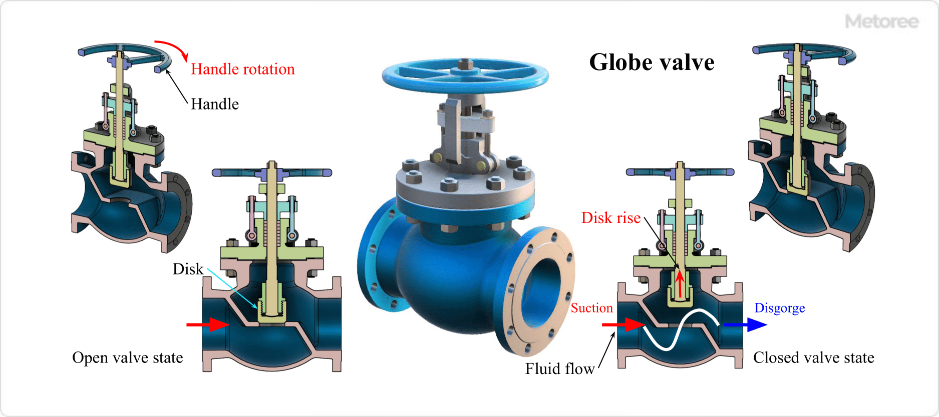
Figure 1. Structure of globe valve

Uses of Globe Valves

Globe valves are excellent for shutting off fluids and regulating flow and pressure, so they are used as stop valves when you want to shut off fluids without leakage. However, due to their high pressure drop, gate valves, ball valves, and butterfly valves with low pressure drop may be used for “always open” applications.

Globe valves are used in utility-related water, steam, and air piping in factories and power plants in general industry, and are often used in facilities and equipment where pipes are laid. It is also used in piping around water meters, gas meters, and water heaters in homes.

Because they are suitable for many applications, including high temperature, high pressure, and large-diameter use, they are used in a very wide range of applications. However, needle valves are best suited for use in small-diameter piping for minute flow rate control. The valve plug is tapered and needle-shaped, making it possible to adjust a minute amount of flow. The basic structure of the needle valve is the same as that of a globe valve, as it is opened and closed by moving the needle valve up and down.

Principle of Globe Valves

The valve plug (disc) in the valve housing (body) of a globe valve is rotated and moved up and down by a handle or actuator (drive unit) attached to the valve stem (stem). This causes the plug to contact the seat (valve seat) and shut off the fluid.

The distance between the valve plug and the valve seat changes to the extent that the handle or actuator is rotated, and the cross-sectional area of the flow path changes, making it possible to adjust flow and pressure. This type of valve is used to adjust the volume of utilities such as steam, cooling water, hot water, compressed air, and vacuum lines that require flow and pressure adjustment.

The valve box is ball-shaped, and the flow path from the inlet, through the valve seat, to the outlet is S-shaped. Inside the valve, the flow direction is changed and the flow path rapidly expands and contracts, resulting in a very large pressure drop.

However, when the valve is closed, the valve plug is pressed against the seat from above, resulting in low leakage and high shutoff performance. In addition, the valve plug position can be finely adjusted, allowing fine control of the flow rate.

Other Information on Globe Valves

1. How to Open and Close the Globe Valve

Globe valves can be opened and closed manually or automatically.

Manual Operation Type
In the manual operation type, the valve is opened and closed by rotating the round handle and moving the valve stem up and down.

Automatic Operation Type

3603_Globe-Valves_グローブバルブ-2.png

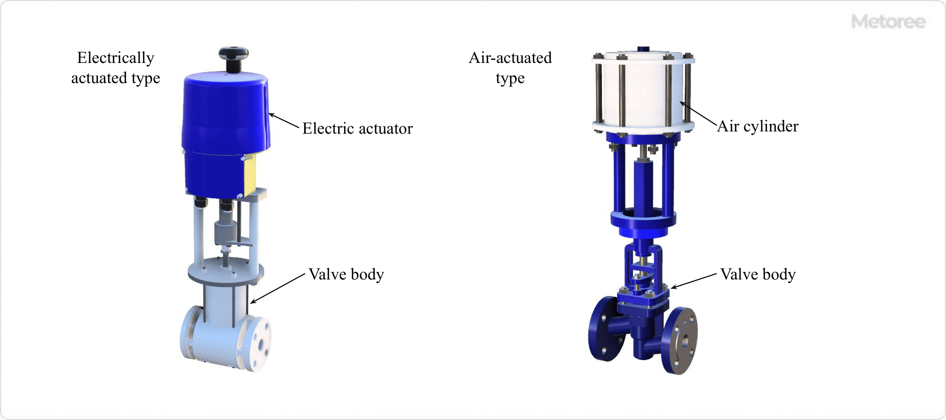
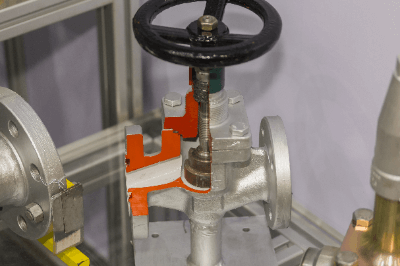
Figure 2. Self-operated globe valve

For self-operated valves, there are two types of actuators (drive units): electrically actuated and pneumatically actuated. Electric actuators use a combination of an electric motor (motor) and reduction gear to move the valve stem up and down to open and close the valve.

On the other hand, the pneumatic actuated type uses compressed air injected into the air cylinder to move the cylinder and valve stem up and down to open and close the valve.

2. Comparison With Other Types of Valves

3603_Globe-Valves_グローブバルブ-3.png

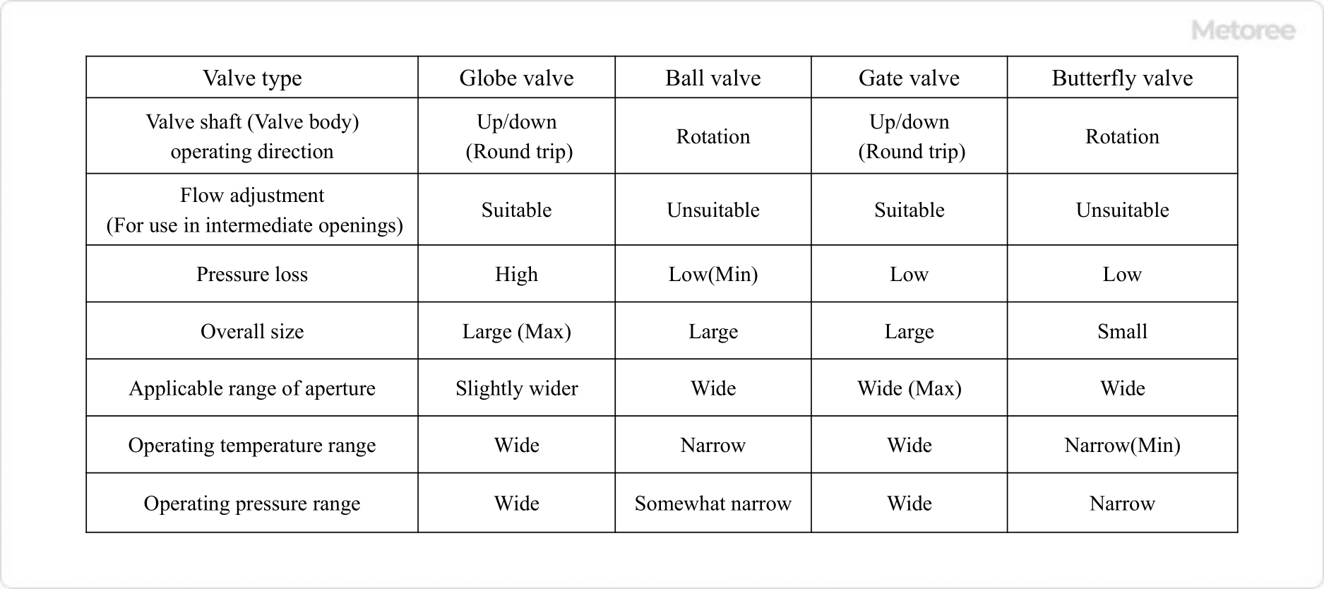
Figure 3. Comparison of valve features

Ball Valve
Ball valves can adjust the flow rate when used in the intermediate opening position. However, when used at the middle opening position, fluid can accumulate between the valve seat (ball seat) and the ball, causing leakage and possible damage to the valve seat.

Therefore, ball valves should be used in fully open and fully closed applications. In particular, ball valves can be easily operated fully open or fully closed by simply turning the handle. However, some manufacturers sell ball valves that can be used in intermediate opening positions.

In general, globe valves are used when both shutoff and flow control functions are required, while ball valves are used when shutoff is the main purpose and full opening and closing can be easily accomplished.

Gate Valves
Gate valves can be used in the middle opening position, but the valve plug may vibrate, so they should be used in the fully open or fully closed position. As with ball valves, globe valves are generally used when both shutoff and flow control functions are required, and gate valves are used when shutoff is the main purpose and full opening and closing can be easily accomplished.

Butterfly Valves
Butterfly valves can adjust the flow rate when used at an intermediate opening position. Butterfly valves have a smaller pressure drop than globe valves, but their disadvantage is that they are prone to unbalanced torque and water hammer due to the plate-shaped valve plug.

Butterfly valves have a smaller valve box and shorter face-to-face dimensions (distance between fluid inlet and outlet), and they have superior shutoff performance. In general, globe valves are used when both shutoff and flow control functions are required and full open/close time can be afforded, while butterfly valves are used when full open/close time is required in a short period and the face-to-face distance is short.

3603_Globe-Valves_グローブバルブ-4.png

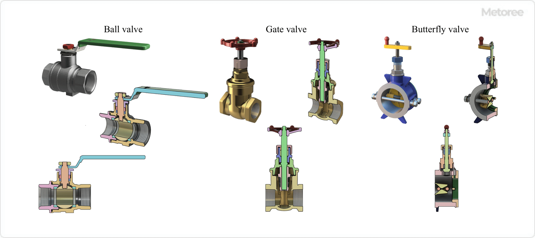
Figure 4. Structure of each valve type

3. Advantages and Disadvantages of Globe Valves

The advantages and disadvantages of globe valves can be briefly summarized as follows.

Advantages

  • Low leakage and excellent shut-off performance
  • Excellent flow control

Disadvantages

  • Time-consuming, requiring multiple turns of the handle or actuator for full-close to full-open operation
  • Large pressure loss in the valve box
カテゴリー
category_usa

Cleaning Rollers

What Is a Cleaning Roller?

Cleaning Rollers

A cleaning roller is a rotating roller designed for the removal of dust, dirt, and other foreign particles from board or sheet products.

Products with a flat or sheet-like form, such as circuit boards or paper, are often transported on rollers. The use of a cleaning roller allows for the inline removal of foreign particles without interrupting the product’s movement along the conveyor.

When compared to non-contact dust removal methods, cleaning rollers excel in their ability to eliminate even firmly adhered foreign matter.

Uses of Cleaning Rollers

Cleaning rollers are employed as part of a dust removal system for the conveyance of board-shaped products and the rolling conveyance of sheet-shaped products (web handling).

Examples of sheet products include paper and plastic items.

Cleaning rollers are frequently utilized in clean room environments because the adhesive roller collects foreign particles that may adhere to the roller, thereby minimizing the release of dust.

Principles of Cleaning Rollers

Cleaning rollers consist of a clean roller, which captures foreign particles like dust and dirt, and an adhesive roller, which transfers these particles from the clean roller to itself. Both rollers possess adhesive properties to ensure efficient particle collection, with the adhesive roller exhibiting a higher adhesive force.

After a certain amount of use, the outermost layer of these rollers can be peeled off to reveal a fresh inner adhesive surface. Periodic replacement of the adhesive roller is necessary to remove accumulated foreign particles. Increasing the diameter of the adhesive roller can extend the replacement interval.

Compared to systems that use compressed air to blow off dust or employ a dust collection nozzle for suction, the cleaning roller operates as a contact-based dust removal system, offering the advantage of securely removing dust and other particles that may be strongly attached due to static electricity. However, for delicate products susceptible to scratches, such as materials prone to quality deterioration upon contact with the cleaning roller, non-contact dust removal systems are preferred.

カテゴリー
category_usa

Climomaster Anemometers

What Is Climomaster Anemometer?

Climomaster Anemometers

Climomaster Anemometer is a multi-functional anemometer manufactured by Canomax, Japan. It is a portable anemometer for measuring indoor environment.

It can measure wind speed, wind temperature, and humidity at the same time. In addition, it can calculate discomfort index, wind volume, and dew point. The major difference between this anemometer and the Anemomaster, also manufactured by Canomax Japan, is that it can simultaneously measure humidity.

It has a high measurement accuracy of 2%, which is in the top class of thermal anemometers, and a wide measurement range of -20°C to 70°C. In addition, the user can exchange probes according to his/her purpose, making it applicable to various situations, such as measurement of indoor air environment and maintenance and inspection of air conditioning equipment.

Applications of the Climomaster Anemometer

Climomaster Anemometer is used in the fields of indoor environment, air conditioning equipment, and inspection control. Specific applications include maintenance and management of air conditioning systems and environmental evaluation of clean rooms. The probe equipped with a sensor is connected to the main unit by a cable, and the probe is directly placed near the exhaust or other airflow opening of an air conditioning system to make measurements. ClimoMaster not only measures air velocity, but also airflow.

The Climo-Master can simultaneously measure not only air velocity, but also air volume, temperature, and pressure. In the field of indoor environment measurement, it can be used to measure the air environment in homes and office buildings, etc., in accordance with the Building Sanitation Law, air conditioning control and environmental measurement in buildings and factories, and measurement of the effect of smoke separation in accordance with the Health Promotion Law.

In the field of inspection and control, it can be used to measure air velocity inside PCs and other equipment to inspect cooling effectiveness, and to test product performance such as drying effectiveness rates.

Principle of Climomaster Anemometer

1. Principle of Hot-Wire Anemometer

3597_Climomaster-Anemometers_クリモマスター風速計-1.png

Figure 1. Principle of hot-wire anemometer

The Climomaster Anemometer is a hot wire anemometer (thermal anemometer). In a hot-wire anemometer, the anemometer sensor is heated. When wind hits the sensor, heat is lost and the temperature of the sensor changes.

As the temperature changes, the resistance of the sensor also changes, and the faster the wind speed, the greater the change. Therefore, by measuring the resistance (or current), it is possible to determine the wind speed.

There are two types of hot wire anemometers: constant temperature type and constant current type. The former keeps the fine wire temperature Tw constant, while the latter keeps the current I constant. The constant-current type, which keeps I constant, is simpler as an electrical circuit, and the Climomaster Anemometer uses the constant-temperature type, which offers superior feedback control.

In this method, the sensor is controlled by a feedback circuit to maintain a constant temperature at all times, but the amount of heat lost from the sensor (amount of radiant heat) varies with the wind speed. The amount of electric current flowing through the sensor to compensate for this changes, and this is how the wind speed value is determined.

2. Principle of Hygrometer

3597_Climomaster-Anemometers_クリモマスター風速計-2.png

Figure 2. Principle of the hygrometer

There are two types of humidity measurement: capacitance type and resistance type. The capacitance type has the advantage of being resistant to low humidity and having a fast response time. On the other hand, the resistive type is inexpensive, resistant to noise, and can be miniaturized, but cannot measure low humidity.

The CLIMOMASTER uses the capacitance type. It consists of a glass substrate, bottom electrode, polymer thin film, and top electrode from the bottom, and the electrodes capture changes in dielectric constant due to absorption and desorption of moisture from the polymer thin film. This change in capacitance is proportional to relative humidity, which is detected.

Features of the CLIMOMASTER

3597_Climomaster-Anemometers_クリモマスター風速計-3.png

Figure 3. About omnidirectional

Climomaster Anemometer is a portable anemometer with a high measurement accuracy of 2% as a hot-wire anemometer. Even though it is a portable anemometer, it has a wide range of functions such as simultaneous measurement of wind speed, wind temperature, and humidity, and calculation functions for air volume and dew point.

Eight types of probes are also available as of May 2023. Each probe is roughly divided into two ranges of wind speed measurement: 0.01~30 m/s and 0.01~5.00 m/s. Omnidirectional probes are also available, which are useful when the exact direction of the wind is not known. The omni-directional probe allows you to measure wind speed without worrying about the direction of the probe, which can measure the absolute value of wind speed in any direction.

カテゴリー
category_usa

Clip Nuts

What Is a Clip Nut?

Clip Nuts

A clip nut is a type of nut that features a nut welded to a plate-shaped clip or a clip-shaped component with a threaded hole.

Clip nuts come in various sizes and lengths to accommodate different applications. The size of the clip part that attaches is determined by the range of board materials it can secure, and the appropriate size should be selected accordingly. While clip nut and nut parts are typically constructed from metal, some products are made of resin, particularly those used in the automotive industry.

Uses of Clip Nuts

Clip nuts are primarily utilized to secure plate-shaped parts and components. In the automotive context, clip nuts are employed to fasten plastic bumper covers at the front and rear of vehicles, as well as plastic undercovers beneath the vehicle’s floor. Many car models use them for attaching license plates to bumper covers. Within the interior of automobiles, clip nuts may be used to affix plastic interior parts in tight spaces. They are also frequently employed to secure exterior parts of motorcycles. In construction, clip nuts find application in securing soundproof walls (sound-absorbing walls) along highways and elevated walls.

Principles of Clip Nuts

Clip nuts are primarily composed of a clip part that grips onto a material or component and a nut part that secures a screw or bolt. By temporarily fastening the clip nut onto a material, it can be pre-attached when there is limited space for fastening a nut or when it needs to be used in multiple locations. This reduces the labor hours required for tightening. Some products feature positioning protrusions on the clamping part. The clip part typically has a U- or J-shaped cross-section, and the appropriate size is selected based on the width of the clip part and the thickness of the plate to be clamped. Most clips are constructed from metal, such as iron (steel) or iron treated with chromate plating to prevent rust. In addition to iron, stainless steel clip nuts are available, albeit at a somewhat higher cost than their iron counterparts.

Clip nuts are available in two main types: those designed for metric screws and those for tapping screws (threads). Clip nuts compatible with metric screws are chosen based on factors such as screw (bolt) thickness, e.g., M3 and M4, and the thickness of the plate material to be clamped. Selection depends on hole diameter, part weight, and required tightening torque. As the clip part size increases with the applicable screw size, it is essential to assess the installation space for the screw. Likewise, select the appropriate size based on the thickness and length of the clip nut screw matching the tapping screw and the thickness of the board material.

カテゴリー
category_usa

Gas Generators

What Is a Gas Generator?

Gas generators are generators that convert gas into electrical energy. They are attracting attention as emergency power generation devices. In Japan, a disaster-prone country, power outages often occur due to typhoons and floods. This is because electricity is shut off to prevent power lines from being cut or leaking due to disasters. However, most of the things we use in our daily lives run on electricity, and power outages can have a major impact on our lives. Gas generators are therefore required to generate electricity using gas, which can be supplied even in the event of a disaster. In places where LP gas is installed, gas generators can provide a stable supply of electricity even if electricity or city gas is cut off.

Uses of Gas Generators

Gas generators are mainly used to supply electricity in times of disaster. By preparing LP gas in advance, power can be generated and electricity can be supplied even in the event of an emergency. Gas generators are in particularly high demand in hospitals and public facilities where electricity is needed even in times of emergency. They are also used as outdoor equipment. Gas generators that can easily generate electricity by setting up a gas cylinder are also available, making it easy to use electrical products in natural areas where it is difficult to secure a power source.

Principle of Gas Generators

There are two main types of gas-based power generation methods. Here we will introduce the principle and features of each.

1. Gas Engine Generator

This method uses the expansion of gas to generate electricity by turning an engine. First, gas or air is injected into the generator. Next, the gas is compressed by a piston connected to the engine. Igniting the compressed gas or air causes rapid expansion, which moves the piston. Finally, the piston motion is converted into engine rotation to generate electricity. Even with its small size, it can generate electricity efficiently.

2. Gas Turbine Generator

This method generates electricity by spraying gas into a turbine. First, gas is continuously burned to generate high-temperature, high-pressure gas. This combustion gas turns the turbine, which generates electricity. This method of power generation has low running costs because it is easy to maintain, and its high heat recovery rate makes it an excellent method for using heat for other purposes. On the other hand, it is not suitable for long-term use because its power generation efficiency is not very high.

カテゴリー
category_usa

Auger Filling Machinery

What Is Auger Filling Machinery?

Auger filling machinery is a device that uses a screw to feed powdery or small granular materials and fill them while weighing them.

Auger means “spiral apparatus” and is named so, because it uses a spiral screw.

They are sometimes called screw-type filling machines.

Auger filling machinery is incorporated into the final process of filling production.

Since the object is powdery or granular and has low fluidity, the fluidity is increased by discharging the filling through the rotation of the screw section.

At the same time, the machine enables quantitative filling of powdery fillings by measuring the prescribed amount at high speed.

Uses of Auger Filling Machinery

Auger filling machinery is used for powdery and granular materials with low dust flutter.

The auger filling machine is unsuitable for large granular materials, as the screw may crush them.

​“【oaicite:1】“​

Food / Pharmaceuticals / Agrochemicals / Petrochemicals / Feedstuff / Ceramics

​“【oaicite:0】“​

  • Flour, potato starch, rice flour, soybean flour, soybean flour, soybean flour
  • Granulated seasonings such as salt, pepper, spices, shichimi, consommé
  • Powdered foods such as scallop powder
  • Granular bath salts
  • Fertilizers, lime
  • Additives
  • Cosmetics such as face powder
  • Baking soda, etc.

Others are available exclusively for toner filling.

Principles of Auger Filling Machinery

Auger filling machinery uses the rotation of the screw section to discharge low-fluidity materials, thereby increasing fluidity and, simultaneously, measuring a specified amount to enable quantitative filling of powdery filling materials.

Some auger filling machines can degas filling, which suppresses dust and increases density by removing air contained in powder during screw conveyance through a degassing filter.

There are two main methods for measuring the capacity of auger filling machinery.

  • Type that weighs by the number of screw revolutions. Each pitch of the screw is used as the unit capacity, and the filling degree is obtained from the number of screw revolutions.
  • The type in which the contents are to be filled is weighed with a scale.

There are also products with various functions depending on the application.

  • Augers that can be removed with a single touch
  • Molded with a single material to prevent foreign matter from mixing in during filling
  • Equipped with a degassing filling mechanism combined with a vacuum device to prevent powder leakage and falling of the filled product
  • Combined with a conveyor for transport
  • Combined with a feeder to enable automatic replenishment of contents

Other manufacturers have lineups that combine with peripheral equipment such as container feeders, cappers, checkers, and labelers.

カテゴリー
category_usa

Oldham Couplings

What Is an Oldham Coupling?

Oldham Couplings

Oldham couplings are mechanical devices designed to connect two misaligned shafts, transmitting rotation between them. Featuring a middle disc that compensates for misalignment between the connected shafts, these couplings are known for their ability to absorb parallel and angular misalignments while transmitting torque. Oldham couplings are favored for their affordability and versatility across various applications.

Applications of Oldham Couplings

Oldham couplings are commonly employed in machinery where precision alignment isn’t possible or cost-effective. Their primary applications include:

  • Connecting drive shafts in machinery with moderate precision requirements.
  • Accommodating misalignment in equipment such as conveyors and pumps.
  • Facilitating quick disconnection and connection in systems needing regular maintenance or configuration changes.

How Oldham Couplings Work

Comprising two hubs and a central disc, Oldham couplings allow the connected shafts to move independently. The disc, slotted to engage with grooves on each hub, slides to accommodate misalignment. This design ensures smooth torque transmission across misaligned shafts without significant efficiency loss or wear.

Key Features

Oldham couplings offer several benefits, including:

  • Ability to handle parallel and angular misalignments.
  • Easy assembly and maintenance due to simple three-part design.
  • Variety of materials to suit different operating environments and torque requirements.

Choosing the Right Oldham Coupling

Selection criteria for Oldham couplings involve considering the application’s torque requirements, the degree of shaft misalignment, and environmental factors. Material choices for hubs and discs vary, with options like aluminum for lightweight applications and stainless steel for higher torque or corrosive environments. Maintenance needs, particularly disc replacement due to wear, also influence the choice of coupling.

カテゴリー
category_usa

Ozone Decomposers

What Is an Ozone Decomposer?

An ozone decomposer is a device designed to break down ozone into less harmful substances. Ozone, while beneficial in the upper atmosphere for blocking ultraviolet radiation, can be harmful to humans and materials at ground level. High concentrations of ozone can cause respiratory issues and degrade organic materials over time.

Uses of Ozone Decomposers

Ozone decomposers are crucial in environments where ozone is generated or used, including water treatment facilities, air purification systems, and industries utilizing ozone for sterilization purposes. They ensure that ozone levels remain within safe limits to protect human health and material integrity.

Principle of Ozone Decomposers

Ozone decomposers typically work by catalytic conversion or absorption methods. Catalytic decomposers accelerate the breakdown of ozone into oxygen using specific catalysts, while absorptive decomposers use materials that react with ozone to remove it from the air.

Types of Ozone Decomposers

There are several types of ozone decomposers, each suited to different applications and ozone concentrations. Common types include:

  • Catalytic Ozone Decomposers: Use catalysts like manganese dioxide to catalyze the breakdown of ozone into oxygen.
  • Carbon-Based Ozone Decomposers: Utilize activated carbon or other carbonaceous materials to adsorb and neutralize ozone.
  • Ultraviolet (UV) Light Ozone Decomposers: Employ UV light to photolytically dissociate ozone molecules back into oxygen.

Choosing an Ozone Decomposer

Selecting the right ozone decomposer involves considering the ozone concentration, volume of air or water to be treated, and specific application requirements. Factors such as maintenance needs, energy consumption, and initial cost also play a role in the decision-making process.

Maintenance and Safety

Regular maintenance is essential for the effective operation of ozone decomposers. This may include replacing catalysts or filters, cleaning components, and ensuring proper airflow or water flow through the device. Safety precautions must also be observed to handle ozone safely and prevent exposure.