カテゴリー
category_usa

Muffle Furnaces

What Is a Muffle Furnace?

Muffle Furnaces

A muffle furnace is a furnace in which a magnetic heating plate is placed inside the furnace, and the heat source is not directly exposed to the sample by using a partition wall (muffle) in which the heater is not exposed.

Electric furnaces used for ceramics and other applications are distinguished from muffle furnaces by the use of exposed heaters inside the furnace.

The metal or powder to be heated, melted, or dried is not directly exposed to the heat source, but the sample is indirectly exposed to the heat source, thus preventing contamination of the sample.

Ceramic fiber, an inorganic fiber mainly composed of alumina and silica, is used as the insulation material inside the furnace and is a chemically stable material resistant to rapid heating and cooling.

Some models can be program-controlled to raise and lower the temperature.

Temperature sensors include R thermocouples, K thermocouples, and B thermocouples, which have different materials and temperature ranges. Therefore, the use of appropriate sensors is recommended.

As safety devices, overcurrent breakers and microcomputer error detection devices are provided.

Uses of Muffle Furnaces

Muffle furnaces are used for firing ceramics (tiles, glass, and insulators) because the atmosphere inside the furnace changes little and requires precise control.

In component analysis tests for heavy metals, arsenic, etc., samples are pretreated and ashed in a muffle furnace for analysis and used in trials for pharmaceuticals and foods.

Muffle furnaces measure the amount of residual material in ashing tests and pharmaceutical and food testing.

Muffle furnaces are used for the heat treatment of glass and metals.

Principle of Muffle Furnaces

The heat source does not expose the heater inside the furnace. The furnace body covers the heater so that the heat source does not directly contact the specimen, eliminating the risk of contamination.

Since the heat source is covered by a bulkhead and not directly exposed, the furnace is made of ceramic fiber with excellent heat insulation and heat retention properties. There are few sudden changes in the atmosphere inside the furnace, and precise temperature control is possible.

Heat plates emitting heat sources are arranged on four sides of the furnace, top, bottom, left, and right, enabling fast temperature rise.

The heat source is an iron chrome wire (normal operating temperature: 850°C) or molybdenum disilicide for higher temperature use (1600°C).

The principle of this heating method is to generate heat by passing an electric current through resistance heating, which is highly efficient because 100% of electrical energy converts into heat.

JIS standard thermocouples, such as R, K, and B, are used as temperature sensors, each of which has a different specified temperature range.

A thermocouple is a temperature sensor consisting of two different types of metal conductors. The difference between the temperature of the object and the room temperature, for example, is detected as an electrical signal.

Since JIS standards control the temperature sensor, it provides reliable temperature control inside the furnace.

To prevent damage, there is a gap between the door and the furnace body (main body), each with a different expansion rate due to heat.

カテゴリー
category_usa

Universal Motors

What Is a Universal Motor?

A universal motor operates on both direct current (DC) and alternating current (AC) power sources, making it versatile for various electrical environments. Known for their high speed and power output in a compact size, universal motors are ideal for applications where space is limited and high performance is required.

However, the use of brushes in universal motors necessitates regular maintenance, as wear and tear from prolonged use or overload can reduce their lifespan.

Uses of Universal Motors

Universal motors are pivotal in both household appliances and professional tools, providing the necessary power and speed for efficient operation.

1. Household Appliances

These motors power vacuum cleaners, offering the suction and speed needed for different cleaning tasks. They are also found in hair dryers, providing quick drying times, and are key components in kitchen appliances like mixers and blenders.

2. Tools

In the field of power tools, universal motors adapt to both AC and battery power, supporting high-speed, high-torque applications such as electric drills, impact wrenches, and electric screwdrivers, essential for effective woodworking, metalworking, and assembly tasks.

Principle of Universal Motors

The operation of universal motors is based on the interaction between the motor’s main components: the rotor, stator, and brush/commutator system.

1. Rotor

The rotor, or the motor’s moving part, typically features an iron core with windings, designed to minimize heat generation through a laminated structure.

2. Stator

The stator creates the magnetic field that drives the rotor, with its coil’s electric current generating magnetism. Lamination reduces eddy current losses.

3. Commutator

The commutator, along with the brushes, supplies power to the rotor’s windings, facilitating the change in power supply polarity essential for rotation.

How to Select Universal Motors

Selection criteria for universal motors include output capacity, rotational speed, and supply voltage, ensuring the motor meets specific application requirements.

1. Output Capacity

Choose a motor with the right power output, measured in watts (W) or horsepower (HP), to match the demands of the task.

2. Rotational Speed

Consider the motor’s speed, indicated in revolutions per minute (RPM), to ensure it aligns with the operational efficiency and speed requirements.

3. Supply Voltage

Select a motor that matches the available power supply voltage, whether it’s for DC or AC applications, to ensure compatibility with the intended environment.
カテゴリー
category_usa

Radial Drilling Machinery

What Is Radial Drilling Machinery?

Radial Drilling Machinery

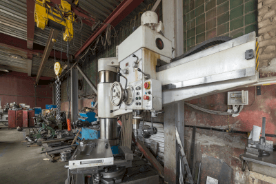
Radial drilling machinery is a type of drilling machine used for machining workpieces.

The table is positioned away from the center of the machine, and the tool can move radially. This machinery is suitable for machining large workpieces and offers high precision.

Specialized attachments and tools can machine complex shapes, but they generally offer less precision than other equipment. Therefore, it’s important to select suitable equipment based on the workpiece’s shape and material.

Uses of Radial Drilling Machinery

Radial drilling machinery is commonly used for:

  • Drilling: Automotive frames, engine parts, etc.
  • Reaming and Tapping: Engine cylinder heads and bolt holes.
  • Grinding and Polishing: Metal parts such as gears and bearings.
  • Finishing: Surface finishing of furniture and wooden crafts.
  • Shape Cutting: Plastic parts.
  • Engraving: Fine engraving on jewelry like rings and necklaces.
  • Repair Work: Drilling holes in automobile body panels.

Principle of Radial Drilling Machinery

Radial Drilling Machinery operates as follows:

1. Fixing the Workpiece

First, fix the workpiece to the table using a clamp or vise.

2. Selection and Installation of Cutting Tools

Select and mount the appropriate cutting tool (e.g., end mill, drill) on the spindle.

3. Setting Cutting Conditions

Set cutting conditions based on the material and tool characteristics. These include rotation speed, feed rate, and cutting depth for efficient and precise cutting.

4. Start Cutting

Begin cutting by rotating the main axis and advancing the cutting tool towards the workpiece.

5. Continuation and Progress of Cutting

Adjust the cutting tool speed and depth based on the changing shape and dimensions of the workpiece.

6. End of Cutting and Finishing

Stop the cutting tool once the desired shape or dimension is achieved. For surface finishing, replace the cutting tool with a finishing tool like an abrasive head or buffing tool.

Radial Drilling Machinery Structure

While structures vary, the basic components are as follows:

1. Base

The base stabilizes the machine and has bolt holes for securing it to the floor.

2. Column (Strut)

A column rises from the base, providing rigidity and accuracy for vertical tool movement.

3. Arm (Radial Arm)

The arm moves along the column, changing the tool’s position. It’s equipped with a tool holder.

4. Table

A flat plate for fixing the workpiece, equipped with clamps and bolt holes.

5. Drill Head

Holds the tool in place and is adjustable.

6. Motor

An electric motor rotates the drill head, with adjustable speed.

7. Spindle (Rotary Axis/Spindle)

The spindle mounts and rotates the tool. It may include a chuck or clamp.

Some models feature a rotating table or replace the table with the base.

Other Information on Radial Drilling Machinery

1. Advantages

Radial drilling machinery is suitable for large, heavy workpieces and offers ease of operation and versatility in material handling.

2. Disadvantages

Limited to specific cutting operations, these machines may have accuracy limitations and can generate noise and vibration, especially with large workpieces. Their size may also require more space.

3. Range of Applications

Applicable for drilling, chamfering, grooving, threading, engraving, pattern cutting, and other detailed work.

4. Types of Cutting Tools

Uses tools like drill bits and end mills.

5. Cutting Speed and Feed Rate

Adjust the cutting speed and feed rate according to the material type and cutting tool for optimal machining quality.

カテゴリー
category_usa

Leak Testers

What Is a Leak Tester?

Leak Testers

A leak tester is a device and chemical product designed to detect leaks in industrial products and various types of piping. These testers can be either inspection devices that electrically detect leaks or chemical products that visually identify leaks.

While the former type inspects for the presence of leakage throughout the product or piping, the latter focuses on identifying the specific location of a leak.

Uses of Leak Testers

Leak testers are commonly used in production line inspections, refrigerant leak checks in air conditioners, and gas piping leak detections.

For production line inspections, the “internal pressure type” pressurizes the inside of the product, and the “internal pressure chamber type” involves placing the product in a pressurized chamber. The “external pressure type” is frequently used for products already in use.

Additionally, “infrared absorption type,” “semiconductor type,” or liquid type leak testers are employed for inspecting products in service, with the “infrared absorption type” being particularly prevalent for detecting flammable or refrigerant gas leaks.

Principles of Leak Testers

In the internal pressure type, leakage is detected by observing pressure fluctuations within the pressurized product. The external pressure type involves placing the product in a pressurized chamber and detecting whether pressure escapes from the chamber into the product.

The internal pressure chamber type pressurizes the product within the chamber and monitors for pressure changes inside the chamber to detect leaks.

Both infrared absorption and semiconductor types detect leaks by identifying gases in the inhaled air. The infrared type offers quick reaction times, while the semiconductor type boasts high sensitivity and longevity.

While inspection equipment checks for leaks, locating the specific leak site requires either a liquid leak tester or submerging the product in water for visual inspection. However, this method may lead to internal corrosion or oversight depending on the product and inspector’s skill.

カテゴリー
category_usa

Linear Actuators

What Is a Linear Actuator?

A Linear Actuator is a device that generates power in a linear direction.

Generally, a rotating motor is converted to linear motion using mechanical components. In addition, there are pneumatic and hydraulic actuators that use cylinders to generate linear motion.

They are widely used as a drive source for parts that require linear motion, such as industrial machinery and computers.

Recently, Linear Actuators are used in industrial equipment and measuring instruments, where high speed and high positional accuracy are required due to their high performance.

Uses of Linear Actuators

Linear Actuators are used in parts that require linear power, such as industrial equipment, automobiles, and PC peripherals. The following are examples of applications where Linear Actuators are used:

  • Opening and Closing Doors of Construction Machinery, Etc.
    Linear actuators are used to open and close doors of heavy machinery such as construction equipment and to adjust the angle of mounted objects. Recently, electric actuators have been adopted, and they can be easily integrated with the control systems installed in construction machinery.
  • Throttle Control for Engines of Construction Machinery, Etc.
    The throttle control system is used to control the throttle of engines of construction machinery. Compared to conventional hydraulic actuators, the linear actuator is smaller and lighter.

Principle of Linear Actuators

The principle of Linear Actuator can be mechanical, pneumatic, hydraulic, or electromagnetic. Each method is explained below:

  • Mechanical Type
    The rotational motion of a stepping motor is combined with a rack and pinion, ball screw, sliding screw, etc. to produce linear motion to obtain linear power.
  • Pneumatic Type
    The pressure in a hollow cylinder is increased by a pump or compressor to raise or lower a piston, which moves the cylinder on the piston axis to generate linear power.
  • Hydraulic Type
    Similar in structure to the pneumatic type, hydraulic pressure is used to raise and lower the piston in the cylinder and move the cylinder on the piston shaft to generate linear power. Compared to the pneumatic type, the hydraulic type is used at higher pressure.
  • Magnetic (Linear Motor)
    Generates linear power by electromagnetic force. The structure consists of a magnet and a coil. When an electric current flows through the coil, it becomes an electromagnet, and the repelling and pulling forces from the magnet generate linear motion and power.

Types and Usage of Linear Actuators

The usage of Linear Actuator varies greatly depending on its structure

  • Mechanical Type
    Since the rotational motion of a stepping motor is mechanically converted into linear motion, the control and positioning methods are the same as those for stepping motors, and a power supply unit or controller for a stepping motor is used. The number of pulses input to the motor first determines the angle of rotation of the motor. With the mechanical origin as a reference, the diameter of the pinion and the number of teeth on both sides for a rack and pinion mechanism, and the pitch of the feed screw for a ball screw mechanism determine the amount of movement per rotation angle.
    The motor can be stopped with high precision by stopping it at a position in the middle of the travel range, and the stepping motor can be used as a brake by applying an electric current to it.
  • Pneumatic Type
    Compressed air is used as the working fluid, so an air compressor or existing compressed air piping is required, and a solenoid valve or speed controller is used for control.
    Basically, the stop position is either at the fully extended position or at the fully retracted position, and it is difficult to control the machine to stop in the middle. By mechanically hitting the stopper, any position can be set as the end point.
    There are two types: the double-acting type, which has a piping connection port at each of the front and rear and controls the position depending on the side to be pressurized, and the single-acting type, which has a connection port at only one end and uses a spring to determine a fixed position.

    If the compressed air pressure is too high, the cylinder may operate vigorously and dangerously.
    In such cases, a speed controller is installed to control the operating speed by throttling the amount of air flowing into the cylinder to achieve the proper operating speed.
    Since air is compressed when pressure is applied, it may not be able to produce the expected force when a large load is applied to the cylinder, etc. On the other hand, even if a fluid leakage occurs, since it is air, it is less likely to contaminate the surrounding area and the fluid can be released into the air after use.

  • Hydraulic Type
    This type uses oil as the working fluid of the pneumatic type and is used when it is necessary to operate at higher pressure, i.e., with greater differential power. Oil is pressurized by a dedicated electric pump.
    Since the operating principle is similar to that of the pneumatic type, it has the same characteristics, but since oil is not compressed even when pressure is applied, a larger differential force can be obtained.
    Since the working fluid is oil, it can contaminate the surrounding area in the event of leakage.

Controlling Linear Actuators

In a mechanical Linear Actuator using a motor, the position is controlled by a contact input that indicates the position or by controlling the rotation of the motor.
Pneumatic and hydraulic types use valves or solenoid valves to switch compressed air or hydraulic circuits for position control.
Some have a built-in proximity switch or potentiometer as a sensor for position detection, which can be retrofitted for use if necessary.

カテゴリー
category_usa

Linear Encoders

What Is a Linear Encoder?


A linear encoder is a sensor-based device that determines the linear position of a moving part. It comes in two main types: incremental, which measures the distance traveled, and absolute, which provides the exact position at any given time, even after power loss.

These devices allow for precise measurement in digital format and can be easily connected to computers or other devices for data logging.

Uses of Linear Encoders

Linear encoders are essential in industries requiring precise positioning, such as in machinery operated by motors, hydraulics, or pneumatics, and in systems demanding accurate, multi-point positioning.

They are commonly found in measuring devices, precision length measurement systems, and semiconductor manufacturing inspection equipment.

Principle of Linear Encoders

Linear encoders consist of a scale with a coded position and a sensor that reads this scale, employing either optical or magnetic detection methods.

1. Optical Linear Encoder

These encoders use light passing through slits or reflecting off a surface to determine position. Suitable for high-precision tasks, they require protection from environmental contaminants, resulting in more complex and larger structures.

2. Magnetic Linear Encoder

Magnetic encoders detect changes in magnetic fields to determine position. They are compact, simple, and resilient to dust, oil, and water, making them versatile for various environments.

While absolute encoders utilize unique patterns for precise location identification, incremental types produce pulse signals for distance traveled, necessitating regular recalibration to avoid misalignment.

Other Information on Linear Encoders

1. Higher Accuracy in Position Detection

As the demand for precision in semiconductor manufacturing and other electronic devices grows, so does the need for accurate position detection. Linear encoders play a crucial role in achieving the high precision required for the production of increasingly integrated and dense semiconductor components.

2. Linear Encoder Resolution and Installation

Key to the manufacturing of precision tools and semiconductor equipment, linear encoders offer resolutions down to the micron level. Installation accuracy is vital for optimal performance, with specific requirements detailed in manufacturers’ manuals. Precision jigs and manual adjustments may be necessary during installation to ensure accuracy.

カテゴリー
category_usa

Linear Shafting

What Is Linear Shafting?

Linear Shafting

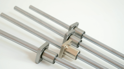
Linear shafting is a wear-resistant, high-precision round bar designed to guide linear (reciprocating) motion. These shafts are typically available with outer diameters in f8, g6, and h5 fits.

Common materials for linear shafting include iron, often with surface treatments like hard chrome, and stainless steel. High-frequency quenching can be used to create a robust surface condition. The shafts come in various shapes, such as straight, pipe-stepped, tapped on the end face, D-chamfered, or key-grooved.

Uses of Linear Shafting

Linear shafting is primarily used as a guide in linear reciprocating motion. They are often combined with dry bearings, linear bushings, or other sliding components to enhance the linearity of movement.

These shafts are commonly found in manual straight-line movement jigs, like vices. Additionally, linear shaft motors, which provide low vibration at standstill and high-speed movement, are gaining popularity in machining equipment where positional accuracy is critical.

Principles of Linear Shafting

Linear shafting plays a crucial role in providing inexpensive, high-precision linear drive and static positional accuracy. Their high standardization allows for achieving precise linear motion cost-effectively and easily.

Subject to wear from constant friction, these shafts often undergo surface hardening to increase durability. However, this hardening can make post-purchase machining difficult without a professional machining center.

While similar to linear guides in function, linear shafting is different in terms of strength and application. Linear guides are preferable for high accuracy and strength as their support points are closer to the load, whereas linear shafting is more suited for applications requiring simplicity and cost-effectiveness.

カテゴリー
category_usa

Linear Bushings

What Is a Linear Bushing?

Linear Bushings

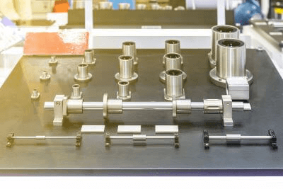
A linear bushing, also known as a slide bush by some manufacturers, is a rolling bearing that facilitates linear motion on a shaft using the rolling motion of built-in balls.

This rolling motion, achieved with minimal friction due to the point contact between the balls and the shaft, allows for smooth movement of the bushing with little force.

Linear bushings, lacking propulsive force on their own, are often paired with mechanisms like cylinders, timing belts, and ball screws to facilitate movement in any direction along a shaft.

Uses of Linear Bushings

Linear bushings are commonly used in combination with linear shafts in sliding mechanisms for various applications such as precision equipment, industrial machinery, medical devices, and office automation equipment, particularly in settings where light loads and minimal vibration or shock are present.

As linear bushings themselves are not powered, they are frequently utilized with cylinders or motors to achieve linear motion.

They enable low-friction, high-precision linear motion between the bushing and the shaft, but careful consideration of shaft deflection and the operating environment is necessary when used under load.

Principles of Linear Bushings

Linear bushings are composed of an outer sleeve, a ball, and a cage. In conjunction with a linear shaft, they achieve linear motion through the rolling of the balls.

The outer casing, made of highly wear-resistant and tough bearing steel, undergoes heat treatment, and its inner and outer diameters are finely ground to facilitate high-precision positioning in linear motion.

The retainer features a guide groove for the ball, ensuring it rolls smoothly along the groove and the inner surface of the outer sleeve. This setup allows for accurate motion with minimal friction due to the point contact between the ball and the shaft.

Selection of linear bushings is based on factors like mounting orientation, travel speed, and usage frequency. Load calculations, rated life, and operating environment considerations are vital, especially when dealing with horizontal guidance under load, where shaft deflection can be an issue.

カテゴリー
category_usa

Riveting Machinery

What Is Riveting Machinery?

Riveting Machinery

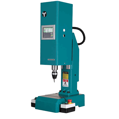
Riveting machinery are machines that join multiple parts by crimping rivets using rotation and pressure.

These machines are commonly used for joining items like scissors, casters, and door hinges. Riveting provides a semi-permanent joint that is less likely to loosen with vibration compared to screws and bolts.

Uses of Riveting Machinery

Riveting machines are used in various industries due to their compact size, safe and convenient operation, and stable performance. They are particularly prevalent in the automotive industry for assembling car body parts such as doors, seats, wipers, hub bearings, and seat belts. Other applications include aircraft, ships, railroad cars, bicycles, turbines, medical equipment, personal computers, cameras, air conditioning units, kitchen utensils, artificial limbs, handcuffs, manhole covers, and electrical switches.

Principles of Riveting Machinery

The riveting machine operates by lowering a forming tool onto the rivet shaft or other protruding parts of the workpiece, pressing down to crimp them. This process can be finely tuned to accommodate variations in workpiece height, thickness, rivet length, and protrusion length.

The method ensures that only the rivet head is pressure-welded and plastically deformed, leaving the body of the rivet intact. This results in stable performance without stressing the joined parts.

Different models of riveting machinery are available, including electric, hydraulic, and pneumatic types, which cater to various needs such as large air-core rivets and solid rivets. The machines come with seven major types of heads — mountainous, round, flat, flat dovetail, round dovetail, pot, and hollowed out — selected based on the desired finished shape.

カテゴリー
category_usa

Roots Blowers

What Is a Roots Blower?

A roots blower is primarily utilized for air blowing, achieved by rotating a pair of blade-shaped rotors.

These blowers typically consist of 2 to 4 blades. The greater the number of blades, the more air can be blown per rotation, thus enhancing efficiency.

The rotor shapes are broadly categorized into involute, cycloidal, and envelope types.

Uses of Roots Blowers

Roots blowers find their application in several areas:

  1. Water Treatment Facilities
    They are employed in septic tanks at water treatment facilities in various institutions like factories, schools, hospitals, etc., for aerating the tanks.
  2. Industrial Vacuum Cleaners
    Roots blowers are integral in vacuum cleaners and dust collectors used in factories for suctioning dust and air, and subsequently exhausting purified air.
  3. Vacuum Trucks
    They are used in vacuum trucks for suctioning sludge and debris in cleaning operations.
  4. Welding Fumes Extraction
    In factories, they are used in industrial vacuum cleaners to extract fumes generated during welding and capture them in filters.
  5. Air Blowing in Factories
    Employed in powering air blowers for removing moisture from products in manufacturing settings.

Principles of Roots Blowers

Roots blowers are designed with a housing body featuring an intake hole and an exhaust hole. Rotors within the blower draw air in through the intake and expel it through the exhaust. During operation, a small gap is maintained between the rotor and the housing, as well as between the rotors themselves, ensuring that they rotate without making contact.

The rotation direction is from the intake chamber to the exhaust chamber, pushing air from the intake to the exhaust. The efficiency of the blower is higher when the gap between the rotor and housing, and between the rotors, is narrower, as this minimizes leakage.

However, an overly narrow gap can risk rotor lock due to foreign objects entering the housing, leading to rotation failure. Therefore, the choice of Roots blower should consider the cleanliness of the operational environment.

Roots blowers are predominantly used in two or three-blade configurations. The two-blade type discharges air four times per revolution, while the three-blade type can discharge six times per revolution, enhancing efficiency but also increasing costs due to the complexity of rotor machining.