カテゴリー
category_usa

Latex Gloves

What Is a Latex Glove?

Latex Gloves

A latex glove is a disposable glove used in laboratories and medical settings. Latex is a natural rubber extracted from rubber trees. Because they are made of rubber, they are soft, fit well on the hand, and provide a non-slip grip, making them suitable for detailed work. However, they have low resistance to oil and chemicals, so caution is needed. In some cases, nitrile gloves made of synthetic rubber are used to avoid allergic reactions in some individuals.

Uses of Latex Gloves

Latex gloves are commonly used in laboratories and medical settings. Due to their low resistance to oil and chemicals, they should be handled with care when dealing with chemicals. The primary concern when using latex gloves is the risk of allergies. Latex proteins in natural rubber can cause itching, hives, and other symptoms upon contact. Frequent use of latex gloves has been reported to increase the risk of allergic reactions, so caution is advised for laboratory and medical personnel.

Principles of Latex Gloves

Disposable gloves come in various types and grades, and selecting the appropriate one for the intended use is essential. Medical gloves, in particular, are subject to strict quality standards defined by JIS (Japanese Industrial Standards).

In addition to latex gloves, other commonly used disposable gloves include polyethylene gloves, PVC gloves, and nitrile gloves.

1. Polyethylene Gloves

These gloves are widely used due to their affordability and ease of use. Many of them comply with food safety regulations and are often used in food manufacturing. However, they do not fit well and are not suitable for detailed work.

2. PVC Gloves

PVC gloves, made of vinyl chloride, are resistant to chemicals and oil, making them suitable for various workplaces. They provide a good fit but are not recommended for use with food.

3. Nitrile Gloves

Nitrile gloves, made of synthetic rubber, offer a good fit similar to latex gloves but are chosen to prevent latex allergies. They have better resistance to oil and chemicals compared to latex gloves, although they are slightly more expensive.

Other Information on Latex Gloves

1. Latex Gloves for Medical Use

Medical personnel use gloves for various purposes, including surgery, examinations, medical checkups, and other tasks. Gloves used in surgery are subject to strict control and are regulated by the “Act on Quality, Efficacy and Safety Assurance, etc. of Pharmaceuticals and Medical Devices” (Pharmaceutical Machine Law).

These gloves are classified as Class 2 “controlled medical devices” and require certification by a third-party certification body for manufacture and sale. Gloves used for examination and medical checkups are treated as Class 1 “general medical devices,” and their manufacture and sale are subject to a notification system.

Ensuring the quality of medical gloves is crucial, and Japan has established five JIS standards for gloves manufactured in the country, depending on their intended use. Each type of glove has defined inspection standards for dimensions (width, length, thickness), pinhole testing, and physical properties (tensile strength, elongation).

  • JIS T9107 “Disposable surgical rubber gloves
  • JIS T9113: Disposable dental rubber gloves”
  • JIS T9114: Disposable dental vinyl gloves”
  • JIS T9115 “Disposable rubber gloves for medical examinations and tests”
  • JIS T9116 “Disposable vinyl gloves for examination and medical examination”

ASTM International is the world’s largest international standardization organization, and several ASTM standards are known for medical gloves:

  • ASTM D3577, “Standard Specification for Rubber Surgical Gloves”
  • ASTM D3578, “Standard Specification for Rubber Examination Gloves”
  • ASTM D6319, “Standard Specification for Nitrile Examination Gloves for Medical Application”
  • ASTM D5250 “Standard Specification for Poly(vinyl chloride) Gloves for Medical Application”

2. Powder-Free Latex Gloves

Some latex gloves are coated with powder on the inner surface to ease wearing. However, the U.S. Food and Drug Administration (FDA) has taken action to halt the distribution of powdered medical gloves due to safety concerns. Powdered gloves made of natural rubber are considered a potential risk factor as the powder can carry allergens, trigger allergies, or increase the risk of granuloma or postoperative adhesion formation.

カテゴリー
category_usa

Distance-Measuring Sensor

What Is a Distance-Measuring Sensor?

A distance-measuring sensor is a device used to measure distances.

They have gained significant use in automated driving systems for automobiles and industrial machinery, and advanced safety systems for collision avoidance. The three primary types of distance-measuring sensors include LiDAR (optical), millimeter wave, and ultrasonic.

Most of these sensors employ a Time of Flight (TOF) mechanism, where a signal is emitted and the time it takes to be received back from the target object is used to measure distance.

Uses of Distance-Measuring Sensors

Distance-measuring sensors are employed differently based on their specific method:

1. LiDAR Method

The LiDAR method, known for its high resolution and accuracy in position and shape recognition, is used in autonomous driving to measure 3D terrain shapes via airplanes and drones, and for object shape recognition. It’s also applied in safety devices for automated guided vehicles to detect obstacle distances, and in systems that identify product shapes and dimensions for automatic sorting.

2. Millimeter Wave Method

The millimeter wave method, notable for its long measurement range and environmental resilience, is used in human detection sensors for movement monitoring within a certain range and in security applications. It’s also employed in adaptive cruise control, collision reduction braking systems, and blind-spot monitors for lane change assistance on highways.

3. Ultrasonic

The ultrasonic method, a cost-effective option, is limited to shorter detection distances of about 10 meters. It’s suitable for motion sensors that activate lights upon detecting a person, for package detection on conveyors, and for car parking obstacle detection.

4. Stereo Camera

Stereo cameras, functioning as distance-measuring sensors, calculate distance from images. Often used in conjunction with millimeter-wave sensors in driver assistance systems, they provide image-based judgment alongside distance measurement.

Principle of Distance-Measuring Sensors

Many sensors use the Time of Flight (TOF) mechanism, where distance is gauged by the time taken for a signal to be sent and received from the target object, depending on the method.

1. LiDAR Method

The LiDAR method uses laser light, which may be visible, ultraviolet, or near-infrared. Distance is calculated by emitting laser pulses and measuring the time to receive reflected light. It is highly precise, detecting small objects accurately, but less suitable for transparent or dusty environments and complex lighting conditions.

2. Millimeter Wave Method

Employing electromagnetic waves in the millimeter wave spectrum, this method comes in pulse and FMCW systems. Pulse systems calculate the distance from the time taken for reflected radio waves to return, while FMCW systems use frequency variation over time and the beat frequency from transmitted and reflected signal interference. This method is effective over long distances, resistant to bright and dusty environments, but less effective with radio wave-absorbing materials.

3. Ultrasonic Method

This method transmits ultrasonic pulses and calculates the distance from the time taken for reflections to return. It’s cost-effective and works in various mediums, but its range is limited to 10 meters, and it’s less effective with sound-absorbing materials.

4. Stereo Camera

Stereo cameras use dual cameras to capture images and gather positional data. The distance to the object is determined by triangulation using the cameras’ positional information. However, image data collection is challenging in dark or strongly backlit environments, affecting detection accuracy.

Other Information on Distance-Measuring Sensors

Familiar Distance-Measuring Sensor Applications

Smartphones often incorporate ToF sensors as distance-measuring sensors. This technology enhances autofocus accuracy in smartphone cameras by precisely calculating the distance between the subject and camera, even in challenging focus environments. It enables 2D images to be processed as 3D data, improving object recognition accuracy in images, with significant potential in virtual and augmented reality technologies.
カテゴリー
category_usa

Synchronous Motors

What Is a Synchronous Motor?

Synchronous Motors

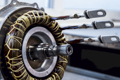
A synchronous motor is an electrical motor that operates in sync with the frequency of the supply power. These motors are known for their ability to maintain constant speed, regardless of power supply frequency or load fluctuations, due to the synchronization of rotor and stator magnetic fields.

For example, a 4-pole synchronous motor supplied with 50 Hz power will rotate at 1,500 RPM. They are preferred for their high efficiency and reduced mechanical losses, enhancing energy efficiency. However, they tend to be costlier than standard induction motors, and those using permanent magnets have higher maintenance costs.

Uses of Synchronous Motors

Synchronous motors are employed in various sectors for applications requiring constant speed and high torque:

1. Manufacturing Industry

They drive pumps, fans, and compressors in factories, offering energy efficiency and constant performance.

2. Processing Machines

Used in machining centers such as milling machines, synchronous motors provide the necessary stable speed for precise operations.

3. Electric Vehicles

These motors are increasingly used in electric vehicles for their efficiency and high torque, contributing to better vehicle performance.

Principle of Synchronous Motors

Synchronous motors consist of a stator, rotor, and enclosure, operating based on magnetic field interactions:

1. Stator

The stator, with its coils, creates a constant magnetic field when excited by three-phase power.

2. Rotor

The rotor rotates in response to the stator’s magnetic field, often containing a hero magnet and winding magnetized by DC.

3. Enclosure

Encased in a robust enclosure, often made of steel, these motors are designed for durability and efficient heat dissipation.

Types of Synchronous Motors

Synchronous motors come in various designs:

1. SPM (Surface Permanent Magnet) Motors

SPM motors have permanent magnets mounted on the rotor’s surface, providing high efficiency and torque density, making them ideal for electric vehicles and industrial applications.

2. IPM (Interior Permanent Magnet) Motors

IPM motors feature permanent magnets embedded within the rotor, offering stability and suitability for high-load conditions.

3. Electromagnet Type Synchronous Motors

These motors use electromagnetic coils in the rotor, allowing for a wide speed range and flexible magnetic characteristic control.

カテゴリー
category_usa

Switching Diodes

What Is a Switching Diode?

Switching diodes are fundamental electronic components, akin to transistors and ICs, and are categorized as active components. In contrast, resistors and capacitors are referred to as passive components.

These diodes are fabricated from semiconductors such as silicon, germanium, and gallium arsenide.

Diodes generally function to maintain a steady current and voltage, and they allow current to flow only in a predetermined direction.

Switching diodes are characterized by their brief switching time, the period needed to switch from a state of conduction, where current flows in one direction, to an interrupt state when the current’s direction is reversed.

Uses of Switching Diodes

In electronic circuits, switching diodes perform two main roles:

  • Rectification
    AC current is supplied from a commercial power source, whereas control circuits in electronic devices are designed for DC.
    The unidirectional current conduction property of silicon diodes is utilized to convert AC to DC, a process termed rectification.
  • Detection
    Silicon diodes are capable of wave detection, which involves extracting video and audio signals from broadcast radio waves, such as those in TV and radio.
    Among various diode functions, switching diodes are specifically employed for rectifying and detecting small signals. They are not designed to manage large current flows in power supply circuits.

Principles of Switching Diodes

Diodes, such as transistors and ICs, are semiconductors, which share properties of conductors, like metals, and insulators, like plastics.

Metals efficiently conduct current due to the mobility of electrons as free carriers. Application of voltage to metals leads to the flow of electric current carried by these free electrons.

Semiconductors, however, can function as both conductors and insulators, depending on the applied current’s state.

P-type and N-type semiconductors differ in how they facilitate current flow. P-type semiconductors, positively charged due to a lack of electrons, rely on electron movement to fill ‘holes,’ while N-type semiconductors, negatively charged with surplus electrons, utilize these free electrons to conduct current.

Switching diodes, formed by combining P-type and N-type semiconductors, are recognized for their fast-switching times and small size, making them ideal for small-signal processing applications.

カテゴリー
category_usa

Scroll Chucks

What Is a Scroll Chuck?

Scroll Chucks

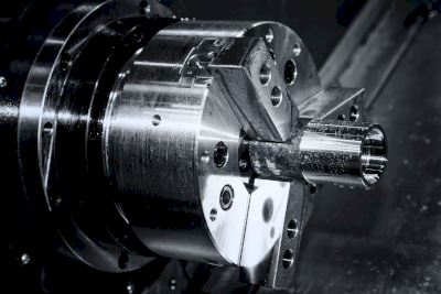
A scroll chuck is a device attached to a lathe’s spindle to hold a workpiece. By manually turning the chuck handle, the three jaws, positioned at 120° intervals, move simultaneously to grip the workpiece.

While scroll chucks typically handle round workpieces, a three-jaw scroll chuck can also grip hexagonal workpieces, and a four-jaw chuck can accommodate square workpieces.

The jaws of the chuck can be custom-molded to fit specific workpieces. In this setup, the jaws are usually secured with a fixture such as a jaw lock or chuck mate, and then bored together on the machine.

Uses of Scroll Chucks

Scroll chucks have been commonly used on general-purpose lathes. However, with the advancement of automation and the prevalence of CNC lathes, the demand for hydraulic power chucks and air chucks has increased, leading to a decrease in the use of scroll chucks.

Still, some manufacturing sites continue to use scroll chucks. The advantage of manual chucking is the ability for experienced operators to make fine adjustments, making scroll chucks a practical choice in some production environments.

Principles of Scroll Chucks

Scroll chucks are distinguished by their internal cam mechanism featuring a spiral groove known as a scroll.

In a three-jaw scroll chuck, there are three pawls spaced at equal intervals, each aligned with the grooves in the scroll. The jaw grooves are positioned differently to ensure the jaws are arranged in concentric circles.

Turning the scroll chuck handle causes the scroll to rotate via the bevel gear, moving the three pawls radially. This movement allows the workpiece to be gripped at the center position.

However, due to the scroll chuck’s design, exact centering of the workpiece is not possible. An average eccentricity of about 0.07 mm is typical and must be taken into account.

To achieve minimal eccentricity during processing, it is essential to minimize clamping changes. If grip changes are necessary, such as for back machining, a four-jaw independent chuck can be used.

カテゴリー
category_usa

Magnetic Stirrers

What Is a Magnetic Stirrer?

Magnetic Stirrers

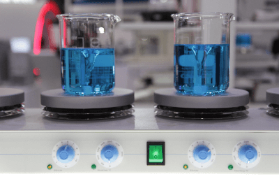
A magnetic stirrer is a device used to stir a solution and generally refers to a magnetic stirrer that rotates a stirrer in a solution on the device by changing the magnetic force of the device itself. There are many different types of magnetic stirrers. The appropriate device must be selected based on the shape and size of the container used in the experiment. For example, a test tube, flask, or beaker, the viscosity of the solution to be stirred, and the experimental conditions, such as whether or not the solution is heated.

In addition to the magnetic stirrer itself, there are various shapes and materials for the stirrer. When selecting a stirrer, it is necessary to choose an appropriate stirrer from the viewpoint of the presence or absence of precipitates in the solution—the need to suppress contamination during stirring, the solution’s viscosity, and the container’s shape.

Uses of Magnetic Stirrers

Magnetic stirrers are used to stir various solutions of water or organic solvents. There are two types of stirrers: Magnetic stirrers, which use a stirrer, and agitators, which use stirring blades connected to the main body of the device. This article will focus on magnetic stirrers.

Magnetic stirrers can be used for stirring solutions in test tubes, beakers, flasks, and various other types of equipment by changing the type of equipment body and stirrer, and are used in a wide range of experimental work, mainly in chemistry and biology. Magnetic stirrers that can stir multiple samples in a single device are also available, as well as stirrers integrated with a hot plate that can be heated during stirring.

Principles of Magnetic Stirrers

A typical magnetic stirrer contains a motor and magnets in the main body of the device, and the magnets rotate the stirrer placed on top of the device. Magnetic stirrers usually use ferrite magnets, but they may also use neodymium magnets, which have high magnetic force, or samarium-cobalt magnets, which do not lose their magnetic force when heated.

Instead of a magnet and motor, an electromagnetic stirrer (magnetic stirrer) uses the magnetic field generated by electricity flowing through a coil. Magnetic stirrers have features such as no performance degradation due to deterioration of the internal magnet and a thin body.

Types of Magnetic Stirrers and Agitators

Various magnetic stirrers are available, differing in capacity, number of revolutions, size, number of stirring points, and with or without a hot plate. You need to select the appropriate device from the viewpoint of the size and shape of the container to be used in your experiment, the viscosity of the solution (whether it is easy to stir or not), whether heating is required or not, cost, and so on.

In addition to magnetic stirrers, various shapes and sizes are also available. Typical examples include:

  • The standard cylinder type.
  • The rugby ball type (less susceptible to rotation speed and vessel shape).
  • The cross-shaped stirrer for dispersing sediments.

Although chemical-resistant PTFE resin is generally used for the agitator exterior, contamination of the sample (contamination) may occur due to abrasion during rotation. To prevent contamination, use stirrers made of PVDF or PEEK.

カテゴリー
category_usa

Slide Shifters

What Is a Slide Shifter?

Slide Shifters

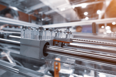
Slide shifters are sliding linear guides.

The linear guides are called different names by different manufacturers, but all have the same basic principle.

They are linear reciprocating guide units with excellent wear resistance, load resistance, and resistance to different physical properties. However, since the guides have no propulsive force, they are widely used in industrial equipment by combining them with other things.

Linear bushings are similar to linear guides, but the ball contacts the rail at a surface, whereas in linear bushings, the ball contacts the shaft at a point.

Uses of Slide Shifters

Slide shifters, as the name implies, are guides. They are combined with ball screws, motors, or cylinders. To provide thrust and positioning, slide shifters are used in many industrial applications, such as lathes, grinding machines, inspection machines, and feeders.

Various types are available, including guide rail types, guide shaft types, and unit types that integrate shift tables, guide shafts, and shaft holders. It is necessary to select the type that best suits the purpose of use.

Features of Slide Shifters

In linear guides, the ball makes contact with the rail on a surface.

Since the ball rolls in the groove and the contact area is large, the linear guide is small but can support a large load. They can also be moved while receiving a load.

About Features:

  • Copper balls roll on a precisely machined surface and are circulated by a return cap.
  • Side seals prevent foreign objects from entering the block from the outside.
  • The compact type has a structure with two rows of balls that contact the raceway at four points.
  • The medium and heavy load types have a structure with four rows of balls that make contact with the raceway at two points.
  • The same load rating is applied to the block in all four directions (radial, reverse radial, and lateral).

Guide Rail:

  • The rails can be connected, allowing a wide range of free design possibilities.

Sliding Linear Guides:

  • A bearing material with excellent wear resistance and low friction supports the linear motion.

Guide Shaft Type:

  • It can be used in any direction, including horizontal and vertical.

Unit Type:

  • Guide shafts, shift tables, shaft holders, etc., are integrated into a single unit.


カテゴリー
category_usa

Solenoid Actuators

What Is a Solenoid Actuator?

Solenoid Actuators

A solenoid actuator is a device that uses electromagnetic force to achieve mechanical motion. Its structure and operation are simple, and it can directly drive a mechanical load, making the entire device small and simple.

There are two types of motion: rotary (rotary solenoid) and linear (linear motion solenoid). Compared to other drive systems, the DC solenoid has superior speed and response.

Uses of Solenoid Actuators

Solenoid actuators are often used when you want to downsize a device or make it move repeatedly at high speed.

Rotary solenoid actuators are used in locking mechanisms for doors, paper roll cutters, optical shutter drives for optical equipment, butterfly valve drives, and flag drives for passage switching.

Linear solenoid actuators are used to drive diaphragm pumps, rollers of card readers, friction brakes, solenoid valves such as air valves, and flow control mechanisms.

Principles of Solenoid Actuators

A solenoid is one of the mechanical components that moves by utilizing the fact that an electromagnet shows properties as a magnet only when the coil is energized. A solenoid has a movable pole made of magnetic material, a fixed pole as an iron core, and a coil around it. When the coil is energized, the fixed magnetic pole and the movable magnetic pole adsorb each other, and when the coil current is cut off, the adsorption force disappears and returns to the fixed magnetic pole to realize a linear reciprocating motion. In the case of rotation, the adsorption force is converted into a force in the direction of rotation.

Solenoid actuators are characterized by the fact that they operate simply by energizing the coil and do not require a driver or other control device like a motor. In the case of rotation, a motor can be moved endlessly, and its speed can be easily controlled by adjusting the voltage. Solenoids, however, can drive a load directly, and thus have high speed and high responsiveness.

カテゴリー
category_usa

Turning Centers

What Is a Turning Center?

Turning Centers

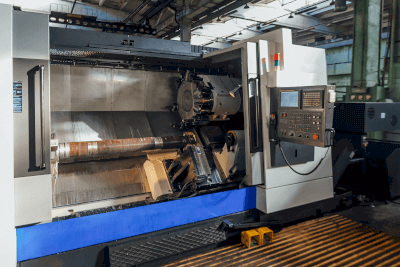
A turning center is an advanced NC machine tool that integrates the capabilities of NC lathes with additional features like rotary tools and automatic tool changers (ATC), enabling milling and eccentric drilling operations.

NC lathes are primarily designed for turning operations and limited to simple center hole drilling, unlike the more versatile turning centers. This allows turning centers to improve work efficiency and productivity without the need to re-fix the workpiece for different operations.

Uses of Turning Centers

Turning centers are ideal for machining workpieces that require multiple processes such as turning, milling, and drilling. The ability to perform these operations simultaneously without setup changes enhances machining accuracy and reduces machining time.

Models with a rear spindle enable rear-side machining by changing grips, with the gripping position adjustable between the leading and back spindles. Those equipped with ATC can also perform complex 5-axis machining. The evolution of turning centers has led to their increasing popularity in recent years.

Principles of Turning Centers

Turning centers come in two main types: NC lathe-based and machining center-based.

NC lathe-based models include an additional rotary axis for tools like drills and milling machines, making them suitable for cylindrical workpieces. Toolholders are often turret type for easy tool changes.

Machining center-based models incorporate additional rotary axes, such as a rotary table, making them ideal for complex-shaped workpieces as 5-axis machines.

Turning centers can be fully automated with additions like a bar feeder or loader for automatic workpiece feeding and discharge.

While the advanced features of turning centers are advantageous, it is important to be aware of potential machine interference due to the many tools, sensors, and robot arms. Safety inspections and meticulous program checks are essential to prevent collisions and machine damage.

カテゴリー
category_usa

Turbine Pumps

What Is a Turbine Pump?

Turbine Pumps

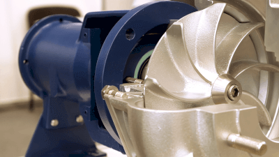
A turbine pump, also known as a diffuser pump, is a type of centrifugal pump equipped with guide vanes for handling high pressures. Commonly used in liquid transport, turbine pumps are efficient in increasing fluid pressure, suitable for high-head applications. They are known for their robustness, reliability, and long service life, but are less effective with viscous fluids or those containing solids.

Uses of Turbine Pumps

Turbine pumps have diverse industrial applications:

1. Power Plants

Used in pumped-storage power plants and thermal power plants, these pumps handle high heads for water pumping and boiler feedwater supply.

2. Water Distribution Systems

In urban and industrial water distribution, turbine pumps efficiently transport water to reservoirs and supply systems.

3. Fire Fighting Systems

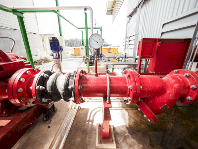
For fire suppression, turbine pumps deliver water to elevated or distant locations, offering compact design and high-pressure capabilities.

4. Seawater Desalination Plants

Essential in desalination plants, they provide the necessary high pressure for seawater processing through membrane filters andevaporators.

Principle of Turbine Pumps

Turbine pumps operate by rotating an impeller, creating a pressure difference that propels the liquid centrifugally. Equipped with guide vanes, these pumps effectively convert kinetic energy into pressure energy, allowing high-pressure discharge.

How to Select a Turbine Pump

Key factors in turbine pump selection include flow rate, head, liquid characteristics, and efficiency:

1. Flow Rate and Head

Choose based on the required liquid transfer amount, elevation differences, pressure, and pipe length to the destination.

2. Liquid Characteristics

Consider the type and viscosity of the liquid, impacting material selection and pump design.

3. Efficiency

Opt for high-efficiency models to reduce energy costs and environmental impact, with larger capacities generally offering better efficiency.