カテゴリー
category_usa

Coriolis Flowmeter

What Is a Coriolis Flowmeter?

Coriolis Flowmeters

A Coriolis flowmeter is a flowmeter that utilizes the Coriolis force.

It is one of the few flowmeters that can measure mass flow and is frequently used in pharmaceutical and food manufacturing processes where mass flow measurement is required.

Most other flowmeters can only measure volumetric flow rate, and to obtain mass flow rate from volumetric flow rate, conversion must be performed using a pressure gauge, thermometer, density meter, etc. Coriolis flowmeters, on the other hand, can only measure volumetric flow rate. A Coriolis flowmeter, however, can provide mass flow measurement results with high accuracy by itself.

Uses of Coriolis Flowmeter

Coriolis flowmeter is mainly used to measure mass flow. Since volumetric flow rates are affected by pressure and temperature, mass flow measurement is used in situations where errors due to these effects cannot be tolerated. Typical examples of applications in a wide range of industries are as follows:

1. Petrochemical Industry

They are used to measure the mass flow rate of raw materials and products during the production of petroleum and chemicals. Where fluid temperatures change significantly before and after product transactions, such as in the transportation of petroleum products. When the properties of a product vary greatly depending on its origin, such as liquefied natural gas (LNG) or liquefied petroleum gas (LPG).

2. Food Industry

They are used to measure the flow rate of liquid or viscous materials in the food production process. For example, it is used to measure the flow rate of chocolate or molasses. 

3. Paper Industry

They are used to measure the flow rate of liquids in the papermaking process. It is also used to adjust the dosage and mixing ratios of various chemical liquids.

4. Medical Industry

Used to measure the flow rate of chemicals used in medical applications. 

5. Fire Fighting

They are used to measure the flow of water in firefighting hoses and water discharge pipes.

In addition to these applications, Coriolis flowmeters are used in a variety of other industrial fields, including the aerospace, automotive, energy, and water treatment industries.

Principle of Coriolis Flowmeters

A Coriolis flowmeter uses the Coriolis force to measure mass flow, volume flow, density, and temperature with high accuracy. Coriolis force is the apparent force that appears when an object is in motion in a rotating coordinate system.

An oscillator is placed inside a U-shaped tube and fluid is allowed to pass through the tube. The oscillator generates lateral vibrations related to the rotation of the tube due to the inertial force generated when the fluid strikes the oscillator. The mass flow rate can be obtained by measuring the phase difference in the torsional angle of the tube that the sensors installed at the inlet and outlet make to the vibration.

The flow tube oscillates at its own vibration frequency, and the density of the fluid can be obtained from the frequency that varies with the density of the internal fluid. A thermometer is installed inside the flowmeter, and this temperature information is used to compensate for the hardness of the flow tube, enabling highly accurate measurements.

Based on the measured information, it is possible to ≈ calculate volumetric flow rate continuously, concentration, specific gravity, etc. Since only the flow tube is in contact with the fluid and there are no moving parts, various types of fluids can be measured with high accuracy.

Other Information on Coriolis Flowmeters

Features of Coriolis Flowmeters

The Coriolis flowmeter has the following three main features:

1. Wide Viscosity Range
A Coriolis flowmeter has a viscosity range of up to 10,000 CP (honey, etc.), depending on the grade of the Coriolis flowmeter. Examples of flowmeters suitable for measuring highly viscous fluids are positive displacement flowmeters, ultrasonic flowmeters, and electromagnetic flowmeters. A Coriolis flowmeter may be advantageous for high viscosity fluids that are slurries (disadvantageous for positive displacement flowmeters and ultrasonic flowmeters) or non-conductive fluids (disadvantageous for electromagnetic flowmeters).

2. High Price
The price of a Coriolis flowmeter is several hundred hundred to several thousand dollars at minimum. This is due to the fact that the Coriolis flowmeter requires advanced technology for machining the pipe inside the device and for controlling the sensor that detects the phase difference of the torsional angle. 

3. Large Pressure Drop
The tube inside the Coriolis flowmeter is designed to be thin, resulting in a large pressure drop. This is to increase the sensitivity of the sensor by increasing the flow velocity in the tube and strengthening the Coriolis force.

カテゴリー
category_usa

Surge Protector

What Is a Surge Protector?

Surge Protectors

A surge protector is a protective device to protect equipment from instantaneous and extremely high voltages and currents caused by lightning strikes and other events.

Surge refers to a voltage of several thousand volts generated by lightning strikes, thunderclouds, and industrial machinery. While lightning is a natural disaster, spot welding, plasma cutting, and other high-voltage operations generate extremely high voltages (spikes) and currents (surges) at the moment of discharge, which can have damaging effects on electronic equipment, controller circuits, and other devices.

Surge protectors are devices designed to mitigate and protect against such incidents. Surge protectors should be installed at the same time the equipment is installed, as surge damage can occur to equipment that may not be affected by surges.

Uses of Surge Protectors

Surge protectors are used where there is concern that equipment may be damaged by high voltage or high current due to lightning strikes or electrical discharges. Specific locations where a surge protector is used are as follows:

  • Near induced lightning (abnormally high voltage) from lightning rods, etc. at the time of a direct lightning strike
  • Near places where large indirect currents due to electrostatic induction flow from the effects of lightning
  • Near power lines and steel towers where high voltage current flows
  • Near motor-driven equipment and factories where high voltage and large currents are generated (e.g., automobile repair)
  • Locations near arc welding machines that emit noise during arc generation or factories that handle arc welding machines
  • Near neon signboards and other areas where high voltage is discharged

Principle of Surge Protectors

A surge protector is a nonlinear element that becomes low resistance when a high-voltage or current surge is applied and releases the surge to the ground side (GND) in a circuit manner. The role of surge protector is to protect various electronic/electrical devices connected to it from damage.

A surge protector incorporates one or more nonlinear elements (elements in which the current flowing through the element is not proportional to the voltage when voltage is applied) to divert surge current and limit over voltage. This element is also called a lightning surge absorber.

Under normal conditions, a surge protector is equivalent to an insulator that does not conduct electricity and has a high resistance to the power supply voltage. When a surge occurs, the built-in nonlinear element instantly changes from a high resistance to a low resistance.

The surge current is then diverted to the ground side, and at the same time, the voltage of the lightning surge is suppressed, after which it returns to its original high resistance, so that the current does not continue to flow. The key to selecting a surge protector is the voltage protection level (maximum surge voltage) based on the residual voltage when the surge is normally handled.

Other Information on Surge Protectors

1. Power Strip Surge Protectors

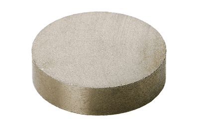
Surge protectors are built into some of the power outlet taps that are frequently used in homes and offices. In this case, the device used for the surge protector application is a lightning surge absorber, commonly known as a varistor.

Varistor is an abbreviation for “voltage variable resistor.” Generally, multilayer chip ceramics are used, and when a certain threshold voltage is exceeded, the device can conduct a large current due to the quantum mechanical tunneling effect.

Although it is possible to configure a circuit with the same function using a forward/reversing diode and parallel capacitance, varistors are usually used because of their disadvantage in terms of area. Protection circuits using varistors are not limited to power strips, but are used in a wide variety of electronic and electrical equipment. 

2. Performance Indicators of a Surge Protector

One of the performance indicators of a surge protector is the maximum surge voltage, which is specified in public standards, including the measurement method.

カテゴリー
category_usa

Thermistor Sensor

What Is a Thermistor Sensor?

Thermistor Sensors

A thermistor sensor, short for “thermally sensitive resistor,” is an electronic component that exhibits a significant change in resistance in response to temperature variations.

These sensors enable temperature measurement by monitoring the resistance of the component. Thermistor sensors are manufactured using a mixture of various metals and can operate within a temperature range of approximately -50°C to 150°C.

Uses of Thermistor Sensors

Due to their affordability, temperature-sensing capabilities, compact size, and durability, thermistor sensors find applications in a wide array of fields:

1. Medical Equipment: Thermistor sensors are used in medical devices for temperature monitoring.

2. Automobiles: They play a crucial role in measuring the temperature of the engine and outside air, ensuring optimal engine combustion and performance.

3. Office Automation (OA) Equipment: Thermistor sensors are employed in various office equipment, including printers and copiers, for temperature control and monitoring.

4. Housing Equipment: These sensors are used in household appliances like water heaters and cooking appliances to measure and control temperature.

5. Industrial Equipment: Thermistor sensors contribute to temperature control in industrial machinery and equipment.

6. **Information Equipment:** They are used in data centers and servers for temperature monitoring and control.

7. General Household Appliances: Thermistor sensors can be found in various household appliances for temperature measurement and control.

For example, air conditioning systems use these sensors in both indoor and outdoor units to maintain optimal temperature conditions. In automobiles, they help control engine temperature and monitor external air temperature. In water heaters, they regulate the water temperature coming out of faucets.

Principle of Thermistor Sensors

Thermistors are made from a mixture of materials, with different types available:

– NTC (Negative Temperature Coefficient) Thermistors: Their resistance decreases as temperature increases, and they are commonly used for temperature measurement and compensation circuits.

– PTC (Positive Temperature Coefficient) Thermistors: These thermistors are used to protect devices from overcurrents rather than for temperature measurement. Their resistance value increases significantly near a specific temperature as temperature rises.

– CTR (Current-Time Resistor) Thermistors: Similar to NTC thermistors, their resistance decreases as temperature rises, but their resistance value decreases significantly at higher temperatures.

Other Information on Thermistors

When using thermistor sensors in electrical circuits, they are typically integrated into the circuit with a constant supply voltage and fixed resistors. As the resistance of thermistor sensors changes with temperature, variations in temperature lead to changes in current flow and voltage across the resistor.

These voltage variations can be read by microcontrollers or other devices with analog-to-digital converter (ADC) capabilities. The combination of thermistor sensors and peripheral circuits often involves connecting a pull-down resistor of 1 kilo-ohm or 10 kilo-ohm to a constant voltage source (e.g., 5 V DC or 3.3 V DC) or connecting a pull-down resistor between the thermistor sensor and ground (GND).

It’s essential to choose appropriate resistor values to prevent excessive heat generation due to increased current flow through the resistor, which can result in inaccurate measurements. In some cases, a known resistor is combined with the thermistor sensor to measure resistance values accurately.

カテゴリー
category_usa

Samarium Cobalt Magnet

What Is a Samarium Cobalt Magnet?

Samarium Cobalt Magnets

A samarium cobalt magnet, a type of rare-earth magnet, is predominantly composed of samarium and cobalt. Known for its strong magnetic force and excellent heat resistance, it does not require plating due to its rust resistance. However, it is prone to chipping and is extremely brittle due to its high hardness.

Applications of Samarium Cobalt Magnets

These magnets are used in high-temperature environments, such as in microwave ovens and magnetrons, automotive motors and ignitions, and various compact devices like actuators, magnetic sensors, microswitches, small relays, and laser devices. Their heat resistance and compactness make them versatile for both industrial and smaller-scale applications.

Properties of Samarium Cobalt Magnets

With samarium and cobalt as their primary components, these magnets boast a high Curie temperature (700 to 800°C), enabling them to maintain magnetism in high-temperature conditions. Their rust resistance stems from the absence of iron. Despite their advantages, the rarity of the materials makes them expensive and subject to price fluctuations.

Other Information on Samarium Cobalt Magnets

1. Ignition Risks

Samarium cobalt magnets can ignite under certain conditions, especially when polished surfaces come into contact with air. They are brittle and can produce flammable metallic powders upon impact. Therefore, they are classified as hazardous materials, necessitating careful handling to prevent the formation of potentially flammable powder.

2. History of Samarium Cobalt Magnets

Research into rare earth magnets began in the 1960s, leading to significant advancements in magnet technology. The discovery in the 1970s that samarium combined with cobalt could dramatically improve magnet performance led to the invention of the samarium cobalt magnet by Dr. Yoshio Tawara in Japan. This magnet’s development, including the Sm2(Co,Fe,Cu,Zr)17 composition, enabled the miniaturization of devices like Sony’s first-generation Walkman.

カテゴリー
category_usa

Thumbwheel Switch

What Is a Thumbwheel Switch?

A thumbwheel switch is a device used for settings that convert the ON/OFF signals of multiple contact circuits into binary, decimal, hexadecimal, or other codes. This conversion is achieved by turning a disc-shaped part known as a rotor. The switch is sometimes referred to as a digital switch or thumbwheel switch.

There are two main types of thumbwheel switches: rotary switches, operated by rotating the switch with a finger, and push switches, activated by pressing a button.

Some thumbwheel switches come with a lock function to prevent accidental changes to the set value, requiring a thin pen nib for operation.

Uses of Thumbwheel Switches

Thumbwheel switches vary in size, with smaller switches typically used in office equipment and consumer electronics, and larger ones in industrial equipment and machine tools.

In industrial equipment and machine tools, these switches are utilized to set operational control values such as time, temperature, and number of cycles. In machine tools, they are used to set dimensional limits for machining, and in motor control, to set microstep counts.

They are also employed in various measuring instruments for setting measurement conditions like frequency, temperature, and time.

Principles of Thumbwheel Switches

Thumbwheel switches consist of simple components such as a case, slide, rotor, sealing plate, packing, printed circuit board, mounting plate, and, for push-operated models, a push button. They are versatile and used in a wide range of applications.

The selected number is visually confirmed on the switch, reducing the likelihood of incorrect inputs. Mistakes can be easily corrected, adding to the usability of these switches.

Since a mechanical mechanism is used for code conversion, the set value remains preserved even during power outages. This mechanical nature also simplifies the circuit and wiring requirements on the output side, enhancing both reliability and maintainability.

Thumbwheel switches are particularly effective in applications where parameters need frequent adjustments according to operating conditions. While many modern systems use large-screen operation panels for parameter settings, there are still numerous instances where hardware-based setting changes are necessary in field conditions.

カテゴリー
category_usa

RF Shielded Room

What Is an RF Shielded Room?

RF Shielded Rooms

An RF shielded room is a room designed to block the effects of external electromagnetic waves and magnetic fields that adversely affect electrical and electronic equipment, and to prevent the emission of electromagnetic waves and magnetic fields to the outside.

Electronic devices that use electricity generate electromagnetic waves, and thus electronic devices and equipment are constantly affected by various electric fields. It is also highly likely that they have an effect on their surroundings. A major role of RF shielded rooms is to eliminate the effects of these electromagnetic waves.

RF shielded rooms are covered with conductive materials such as metal or wire mesh. It may be constructed from new construction, or in the case of an existing building, assembled with panels that can be assembled inside. The purpose of use, the measurement details, and the location where you want to install it. The design is based on the environment and other factors.

Uses of RF Shielded Rooms

RF shielded rooms are used to eliminate the adverse effects of electromagnetic waves. Specific applications are as follows:

  • Measurement rooms with bio-magnetic field measurement equipment, such as MRI, magnetoencephalography, and magnetocardiography
  • Computer rooms for confidentiality purposes
  • Measurement rooms for electromagnetic interference and laboratories for signal evaluation without the influence of electromagnetic interference
  • Recording studios

It is used to provide an environment for product development and quality control of precision instruments and electronic devices. RF shielded rooms are also used to prevent electromagnetic noise (unwanted radio waves) generated by equipment and devices inside a facility from affecting equipment and devices outside the facility.

Principle of RF Shielded Room

Electromagnetic shielding uses the property of conductive materials such as wire mesh and metal plates to reflect electromagnetic waves. RF shielded rooms are rooms covered with these conductive materials.

What is important in producing RF shielded rooms is not only to shield the electromagnetic waves generated in the space or influenced by the outside, but also to shield the electromagnetic noise leaking from both sides. In particular, shielding of openings (doors, windows, air conditioning openings, etc.) is a key point.

RF shielded rooms can be classified into the following three categories according to the purpose and frequency range to be handled.

  • For Electrostatic Shielding
    RF Shielded Rooms are used to maintain a constant electric potential in a room. (EEG rooms, hearing test rooms, etc.)
  • For Magnetic Shielding
    RF Shielded Rooms are generally used for geomagnetic fields up to 10 kHz
  • For Planar Electromagnetic Shielding
    RF Shielded Room for 10kHz to 40GHz. (Noise testing rooms for electronic equipment, anechoic chambers, recording studios, etc.)

Shielding in EMC countermeasures often refers to electromagnetic shielding. Electromagnetic shielding is often used for EMC and immunity measures for electronic equipment.

Other Information on RF Shielded Rooms

1. Difference Between Rf Shielded Room and Anechoic Chamber

RF shielded rooms are characterized by shielding the entire room, down to the doors, air conditioning, and power supply, in order to shield electromagnetic waves. On the other hand, an anechoic chamber is further covered with a radio wave absorber to suppress the reflection of radio waves completely.

The absorber has a spongy, thorny shape and contains carbon powder and ferrite components. By covering the entire surface of the room with the absorber, the incident electromagnetic waves can be attenuated to about 1/100,000 of their original volume. Electromagnetic waves cannot exist in an anechoic chamber, which is sometimes called a radio wave anechoic chamber. 

2. Antenna Evaluation in an Anechoic Chamber

While the main purpose of RF shielded rooms is to evaluate the quality of the target signal itself by blocking out interference and noise, antenna emission tests are often conducted in an anechoic chamber, taking advantage of the non-reflective nature of electromagnetic waves.

Directionality testing of radio waves is essential for mobile communications, including millimeter wave, automotive radar, and sensing technology. An anechoic chamber is an indispensable environment for evaluating the shape of the radiated beam of an antenna and the electrical characteristics of the antenna itself.

3. Shield Boxes and Anechoic Chambers

Since an anechoic chamber is a very large device, it is costly, including maintenance. RF shielded rooms are less expensive than anechoic chambers because of the radio wave absorber, but still have a certain cost.

Similarly, an anechoic box type is also widely used for various evaluation purposes because of its convenient size.

カテゴリー
category_usa

Jet Oiler Spout

What Is a Jet Oiler Spout?

Oiler SpoutsA jet oiler spout is a device designed for lubricating machinery and equipment effectively.

It is particularly useful for supplying oil to areas prone to friction and high-speed rotating parts. Jet oiler spouts operate by injecting jets of oil using compressed air, ensuring efficient lubrication and cooling.

These spouts disperse oil in the form of a fine spray, ensuring uniform distribution on the machine’s friction surfaces for effective lubrication. This helps in maintaining smooth machine operation and prevents wear and heat-related breakdowns.

However, it’s important to note that jet oiler spouts, as they spray oil, can pose a risk of oil leakage from the nozzle and connections. Proper sealing and leakage prevention measures are necessary to avoid environmental and workplace issues due to oil leakage.

Uses of Jet Oiler Spouts

Jet oiler spouts find applications in various fields:

1. Transportation Equipment

In ships, these spouts are used to lubricate high-speed rotating parts such as main engines and rudder wheels, ensuring efficient and stable machinery operation.

They are also employed in airplanes for lubricating high-speed rotating parts like engine drive units and turbochargers, contributing to optimal engine performance, efficiency, and reliability. In automobiles and motorcycles, they enhance component durability and fuel efficiency.

2. Energy Industry

In the energy sector, jet oiler spouts are used in power plants to lubricate high-speed rotating parts of turbines and generators, ensuring efficient power generation and stable operation. They are also employed in wind turbines to extend machine life and improve power generation efficiency.

3. Manufacturing

Machine tools like milling machines and drilling machines use jet oiler spouts to lubricate cutting tools and bearings of rotating parts, reducing friction, and improving precision and tool lifespan. In press machines, these spouts are used for lubricating press parts and dies, enhancing quality and tool longevity. They are also employed in conveyors to lubricate rollers and bearings.

Principle of Jet Oiler Spouts

Jet oiler spouts are designed to drip or inject oil or adhesives, allowing precise control over the quantity and location of the discharge. They are smaller in size compared to sprays and jockeys, making them space-efficient for storage.

These devices consist of a tank and nozzles. The tank stores a fixed amount of lubricating oil and dispenses it as needed. Tank sizes range from small ones (20 ml or less) to large ones (400 ml or more), with smaller oilers being suitable for easily degradable liquids.

Nozzles equipped with fine holes and jets inject oil in the form of a fine spray or jet. Ultra-fine nozzle types are available for use in extremely confined spaces. Jet oiler spouts can be made from metal or plastic, and the choice of material should match the type of liquid used.

How to Select a Jet Oiler Spout

When choosing a jet oiler spout, consider the handle and other features. There are two main types: those with a grip lever and those with a pushable plastic tank body. Selection should be based on ease of use and intended application.

The tank’s capacity is another factor to consider. Opt for a larger oiler if you require a significant amount of oil or are working with a non-degradable liquid.

Nozzles come in various shapes, including horizontal or slightly curved tips, and straight-up, or angled nozzles. Select the nozzle shape that best suits your specific application requirements.

シュリンク包装

監修: サトルパック株式会社

シュリンク包装とはシュリンク包装

商品(包装物)を熱収縮フィルムで包み、熱をかけてフィルムを収縮させ、商品(包装物)の形状に密着させる包装です。熱に反応して縮小するフィルムですので様々な商品に対応できます。シュリンクは、「縮小」「収縮」「縮む」という意味です。近年シュリンクフィルムメーカーの開発も進み、シュリンクフィルムの種類や厚さ等も増えてきております。フィルムの厚さを上げれば強度も強くなり、重量物や突起のある包装物にも対応できます。

シュリンク包装の使用用途

シュリンク包装は、密閉包装を必要とする食品や化粧品、医薬品など、様々な製造分野において活用されます。

以下に、使用例の一部を列挙します。

  • 箱(化粧箱、ギフト箱、段ボール箱、御節、プラスチックボックス、通関箱など)
  • 容器(食品、食品トレー、フードパック、弁当、丼、紙皿、スプレーボトル、ボトルなど)
  • 柔らかいもの(スポンジ、タオル、衣服、シューズ、パン、ぬいぐるみなど)
  • 特殊な形(玩具、介護用品、冷凍かに、置物、機械部品など)
  • 重量物(印刷物、木材、基盤シート、籠盛、機械部品など)
  • 台紙に固定(通半事業商品、輸送保護、生活用品、化粧品、医薬品、自動車部品など)
  • 3次元測定サービスの原理

 L型シュリンク包装機の種類

1. 簡易型シュリンク包装機

L型シーラー機とシュリンクトンネルが1台の機械になっており、1回のサイクルで包装・シュリンクが完了する小ロット多品種向けの機械。省スペースでの設置、電源さえあれば使用可能です。

・1分間の生産数:〜4個

・多品種・小ロットの包装を行いたい方

2.半自動シュリンク包装機

自動シュリンク包装機のL型シーラー部が人手で商品(包装物)を投入、フットスイッチかサイクル運転により包装させシュリンクトンネルでフィルムを収縮させる。自動機よりは少し生産能力は劣ります。

・1 分間の生産数:〜10 個
・複数品目の包装を行いたい方

3.自動シュリンク包装機

商品(包装物)はコンベア上に乗せるだけでフィルムで商品を包む自動L型シーラー機とフィルムを熱収縮させる為の炉、シュリンクトンネルから成り立つ量産タイプの機械です。

・1 分間の生産数:〜20 個
・1 つの品目で量産を行いたい方

本記事はシュリンク包装機を製造・販売するサトルパック株式会社様に監修を頂きました。

カテゴリー
絶対に触らないでください(日本会社ニュース)

年末年始休業のお知らせ (2022年12月29日-2023年1月4日)

平素よりメトリーをご利用頂き、誠にありがとうございます。

2022年12月29日-2023年1月4日の間は、年末年始休業とさせて頂きます。

上記期間内にお問い合わせ頂いた内容に関しては、順次2023年1月5日以降に対応させて頂きます。

2023年も、研究者・エンジニア・購買担当者の方々のサポートを行うことで、世界の発展に少しでも貢献できるよう、メトリーの開発に邁進します。

カテゴリー
category_usa

Coating Process Equipment

What Is Coating Process Equipment?

Figure 1. Types of Coating Equipment

Coating process equipment is used to apply chemicals to products or materials.

Coating process equipment generally uses various coating methods such as roll coaters, spin coaters, dip coaters, spray coaters, and dispense coaters, depending on the shape of the object to be coated, the chemical to be coated, and the purpose of the coating.

In recent years, coating process equipment has evolved dramatically along with improvements in coating technology, as precision coating accuracy is required in industrial fields such as semiconductor manufacturing, flat panel display (FPD) manufacturing, solar cell and rechargeable battery manufacturing.

Uses of Coating Process Equipment

Coating equipment is used to apply coating liquids to objects in a variety of manufacturing processes, such as in the semiconductor field and secondary battery manufacturing. Spin coating process equipment is often used to apply photoresist in the photolithography process in the semiconductor and flat panel display (FPD) manufacturing fields, which require particularly thin, high-performance, high-density devices such as PCs, LCD TVs, smart phones, and tablets.

For functional films and sheet products used in rechargeable batteries, solar cells, automotive parts, housing construction materials, textiles, medical care, etc., roll, spray, and dispense coating process equipment are used to apply chemicals such as sealants, adhesives, and electrode materials.

Principle of Coating Process Equipment

Figure 2. Features of Coating Equipment

Figure 2. Features of Coating Equipment

Coating process equipment is used to apply materials such as correspondence and chemicals to various production materials. They can be broadly classified into roll, spin, spray, and dispense dispensing systems.

1. Roll Coating Process Equipment

Roll coating process equipment is generally used for coating relatively thin and flat materials such as films and sheets.

Various coating methods are used depending on the nature and viscosity of the chemical to be applied and the film thickness to be applied, such as gravure coaters and reverse coaters that use the rotation of a roller in contact with a liquid reservoir of the chemical to be applied and the winding rotation of the film or sheet material.

Roll-to-roll coating is possible, and this method is most suited for high-speed coating. The characteristic feature of these methods is that a bead is formed between the coating liquid and the object to be coated, and the object to be coated or both the object to be coated and the roll are moved or rotated to apply shear force to the coating liquid and thinly apply it.

Stabilizing this bead is essential for high-quality coating.

2. Spin Coating Process Equipment

Spin coating process equipment is used in the photolithography process in the semiconductor and flat panel display (FPD) manufacturing fields. This is the thinnest coating method.

This is the thinnest coating method, but it is not suitable for mass production because it cannot apply multiple coats and continuous production is not possible.

3. Spray Coating Process Equipment

Spray coating process equipment converts chemicals into fine particles and applies them to automobiles, exterior walls, building materials, and other large objects.

Three types of methods exist for generating granular spray: air, electric, and ultrasonic.

4. Dip Coating Process Equipment

Dip coating process equipment is a method in which the object, regardless of its shape, is dipped into the dip coating solution and pulled up. It can form a uniform thin film and is used for optical lenses, medical systems, electronic devices, and other applications.

Dip coating process equipment is characterized by its ability to form a uniform thin film with minimal loss of coating solution, regardless of the shape of the object.

5. Dispensing Coating Process Equipment

Dispensing coating process equipment is used in situations where relatively precise linear coating is required. This coating process equipment is equipped with a dispensing mechanism that can control the amount of coating, and when even more precise coating is required, a robot is used to provide both accuracy and precision in the amount of coating. Although the dispensing speed is of course inferior, spot dispensing to small areas and coating films of complex shapes can be formed.

Other Information on coating process equipment

Coating Defects and Coating Process Equipment

Figure 3. Lack of Coating and Coating Equipment

Figure 3. Lack of Coating and Coating Equipment

No matter how sophisticated the Coating Process Equipment is, a clean coated surface may not be obtained depending on the coating conditions, such as a coating fluid with an incompatible viscosity or coating speed. The types of coating defects and their remedies are as follows.

1. defects caused by coating

Defect   Cause Remedy
Air entrainment Occurs when air cannot escape during the application of the coating liquid to the coated object. Solved by reducing the coating speed.
Livestock This occurs when there is a reverse pressure gradient in the coating section in the direction of the coating. Solution is to reduce the viscosity of the coating liquid and the coating speed.
Strips and holes caused by air bubbles This is caused by the presence of bubbles in the coating liquid. Take measures to eliminate bubbles.
Uneven horizontal damping Occurs mainly in reverse gravure coating systems. Solution is to suppress vibration of the coated object or change the rotational speed of the gravure.
Unevenness Unevenness is caused by the flow of coating liquid in the coating film. This is solved by improving the coating liquid.
Foreign matter Coating liquid agglomerates or becomes gelatinous. This can be solved by introducing a filter, etc.
Flickering is caused by the high surface tension of the coating solution. This is caused by the high surface tension of the coating liquid. Add a surfactant or other agent.

2. Defects caused by drying

Defect Cause Remedy
Yuzuhada (uneven coating surface like yuzu peel) This defect occurs when the drying speed is too fast. This defect is caused by drying too fast, and can be corrected by reducing the drying speed or adding a surfactant.
Wind ripples Occurs during hot-air drying. This is caused by hot-air drying, and can be handled by reducing the speed of the hot-air blow.
Cracking Occurs due to shrinkage of the coating film. It can be solved by reducing the thickness of the coating.

Coating is a technology that can be achieved by appropriately selecting Coating Process Equipment, Drying, and Coating Liquid. It is important to select the appropriate Coating Process Equipment, taking into consideration the conditions of the coating liquid to be used and the specifications of the drying oven.