カテゴリー
category_usa

Dial Indicator

What Is a Dial Indicator?

Dial Indicators

A dial indicator is a measuring instrument used for measuring the length and runout of a workpiece. Similar in shape and function, some products are referred to as dial gauges.

Positioned on a foundation, a dial indicator measures the dimensional variance of a workpiece compared to a standard model, such as a block length gauge. Measurements can be in hundredths or thousandths of a millimeter. Accuracy is contingent on controlled temperature, measurement method, and the condition of the foundation and workpiece; without these controls, significant errors may occur.

Uses for Dial Indicators

Dial indicators are utilized in various applications, including:

  • Measuring parts in precision instruments.
  • Measuring small-diameter components.
  • Assessing the runout of circular parts.

Initially, the base of the dial indicator is set on a stable platform, with gauges or indicators placed on the base’s tip.

Next, a dimensional standard is positioned on the base, adjusted to be within the measurable range by touching the tip, and the indicator needle is set to 0 (zero).

After removing the standard, the workpiece is placed between the base and the measuring element. The needle’s indication at this point represents the dimensional difference between the standard and the workpiece, allowing for accurate measurement of the workpiece’s dimensions.

Principles of Dial Indicators

Dial indicators come in two types: the spindle type, where a rod-shaped measuring element moves vertically to indicate dimensional differences, and the lever type, used in confined spaces where the spindle type cannot fit.

The spindle type, common for simple shapes, features a vertically moving measuring element that can be easily aligned perpendicular to the base.

The lever type, ideal for narrow areas, has a tilting measuring element around its base. It must be installed nearly perpendicular to the direction of dimension change in the workpiece at the measurement point.

In both types, the measuring element’s motion causes the hand to swing like a clock. Dimensional differences from the standard are determined by setting the standard dimension to 0 on the model and reading the needle display while measuring the workpiece. Attention should be paid to the display’s resolution and the number of needle rotations, which must be visually confirmed during measurement.

With a defined measurement method and temperature control, even measurements in thousands of a millimeter can be achieved with high accuracy.

カテゴリー
category_usa

Angular Contact Ball Bearing

  • What Is an Angular Contact Ball Bearing?
Angular Contact Ball Bearings

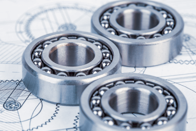
An angular contact ball bearing has contact angles between the balls and the inner and outer rings.

Angular contact means that the line connecting the contact points between the inner ring and the balls and the contact points between the balls and the outer ring is not perpendicular to the axis of rotation (do not intersect at 90°). In a standard radial ball bearing, the line connecting the two points of contact between the inner and outer rings and the balls is perpendicular to the axis of rotation of the bearing.

Angular means angle and the contact angle permits radial loads (loads perpendicular to the axis) and axial loads (loads horizontal to the axis) in one direction up to a certain amount.

Uses of Angular Contact Ball Bearings

Angular contact ball bearings are used in hydraulic pumps, vertical pumps, compressors, elevator hoisting machines, belt conveyors, etc., because they can tolerate a certain amount of radial and axial loads in one direction.

Connecting two or more of them can support axial loads in both directions or even more axial loads in one direction. When two or more bearings are assembled, it is essential to determine the orientation of each bearing after carefully checking the load to be supported in each direction.

Principles of Angular Contact Ball Bearings

There are several types of bearings, which can be divided into rolling bearings and plain bearings. Rolling bearings are often used in cars and industrial machinery. Rolling bearings are mainly composed of the following three elements:

  • Raceways (inner and outer rings in which balls and rollers roll)
  • Rolling elements (balls or rollers that roll between the inner and outer rings)
  • Retainer (the part that prevents rolling elements from colliding with each other or falling out of the raceway)

In addition, angular contact ball bearings have contact angles between the raceways and rolling elements. The larger this angle, the larger the allowable axial load. However, it is vital to select the proper angle, as this may require a reduction in rotation speed.

Other Information on Angular Contact Ball Bearings

  1. Contact Angle of Angular Contact Ball Bearings

The standard contact angles of angular contact ball bearings are 15°, 30°, and 40°, which are indicated by the symbols C, A, and B, respectively. The allowable axial load and allowable rotational speed vary depending on the size of the contact angle.

When used at high rotational speeds, a small contact angle is often selected, and when the axial load is large, a large contact angle is often selected. The contact angle also makes it possible to combine two angular contact ball bearings and apply a pressurizing force, improving rotational accuracy and rigidity.

  1. Pressurizing Angular Contact Ball Bearings

The amount of pressurization is determined by combining bearings in opposite directions and controlling the internal clearance. There are two types of combinations for pressurization: frontal and backward varieties, represented by the symbols “DF” and “DB.” In addition, there is a parallel combination “DT” with opposing combinations.

Pressures are classified as “fine,” “light,” “medium,” and “heavy” and should be selected according to the conditions of use. Each pressurization amount is determined by the bearing size and is described in the technical data of each manufacturer. When applying pressure, care should also be taken not to increase the pressure too much, for example, by slightly changing the dimensional tolerances of the parts to be installed.

If the pressurization is too large, rigidity will increase, but resistance to rotation will increase, which may cause problems such as increased heat generation or bearing deformation. There are several ways to apply pressure, but the constant-pressure and fixed-position methods are generally used.

  • Constant pressure method
  • This method uses a spring or other means to apply a constant force to the bearing, and the pressurization can be maintained constant even if the bearing wears out. However, the disadvantages are that the structure is complicated, and the calculation of the spring force is necessary.
  • Fixed-position method
  • A spacer is placed between the two bearings. The amount of pressurization is adjusted by controlling the thickness of the spacer. Although the amount of pressure applied changes as the bearings wear, this method is often used because of its simple structure.

Although pressurization is indispensable for the accurate use of angular contact ball bearings, it must be considered following the operating conditions when designing the bearings. Mounting parts must also be finished with high precision.

カテゴリー
category_usa

Industrial Computer

What Is an Industrial Computer?

Industrial Computers

An industrial computer is a specialized computing device tailored for specific tasks or purposes in various industrial fields, including factory operations, equipment control, and medical equipment. Unlike general-purpose personal computers, industrial computers are built for high durability and reliability, essential for long hours of operation in challenging environments.

These computers offer long-term stable supply and maintenance, making them vital in advancing industrial development.

Uses of Industrial Computers

Industrial computers serve a wide range of functions:

1. Manufacturing Industry

They are crucial in controlling manufacturing lines, ensuring quality control, and managing production planning and inventory. In the automotive and semiconductor industries, they operate robots and machinery with precision and detect product defects.

2. Medical and Welfare

These computers process data for medical equipment, generating and analyzing high-speed, high-precision images in diagnostic imaging tools like MRI and CT scanners. They also monitor patient vitals and manage treatment in life-support devices.

3. Transportation and Logistics

Industrial computers streamline operations in public transportation and logistics facilities, handling tasks from scheduling to safety assurance and optimizing warehouse management.

Principles of Industrial Computers

Industrial computers are designed to endure harsh conditions like high temperatures, vibration, and dust. They emphasize reliability and maintainability for long-term stable operation. They consist of both hardware and software components designed for industrial environments:

1. Hardware

Their hardware features high durability, reliability, expandability, and environmental performance.

2. Software

Software aspects focus on reliability, resistance to bugs and viruses, ease of maintenance, and usability.

Other Information on Industrial Computers

Price of Industrial Computers

As industrial computers become more integrated into IoT and M2M technologies, their application fields are expanding. However, the cost of implementation can be a concern. Here, we provide reference prices for different types of industrial computers, but actual prices can vary based on specific applications.

Examples include high-performance PCs for medical image viewing (~1,000,000 Yen), simulation PCs (~ ¥800,000) with significant memory and CPU capacity, and servers/data registration machines (~400,000 Yen) for factory networks.

カテゴリー
category_usa

Hand Operated Valve

What Is a Hand-Operated Valve?

Compressed air is used as a power source in various production equipment such as machine tools, conveying equipment, and inspection equipment.

Compressed air is sent to production equipment, which drives air cylinders to transport products, robots to clamp products, and air blowers to clean products.

Hand-operated valves are devices that allow operators to manually change airflow direction in piping or air tubes, stop air flow, or adjust the flow rate using a lever or handle for switching.

Uses of Hand-Operated Valves

Hand-operated valves are used for the following applications:

  1. Speed control of conveying equipment
  2. Equipment (loaders, shifters, etc.) that removes products from machine tools and transfers them to subsequent processes may cause products to fall or shift position due to vibration if the transfer speed is too fast.
  3. The airflow rate can be adjusted with hand-operated valves to change the speed without causing problems.
  4. Switching valve for interchangeable jigs
  5. Jigs may be replaced when changing models in equipment that processes a variety of products.
  6. The air hose must be disconnected and replaced for jigs with air cylinder clampers.
  7. Air leaks can be prevented by stopping the air supply to the jig with the switching valve and then disconnecting the hose.

Features of Hand-Operated Valves

There are various types of hand-operated valves, each with distinct features:

Residual Pressure Relief Valve

  • When production equipment is stopped during a process due to an abnormality, it is dangerous to take action while air pressure remains in the equipment.
  • The cylinder may become unhooked for some reason and suddenly recoil, possibly injuring the operator.
  • For this reason, hand-operated valves for releasing residual pressure can be attached to the piping route so that safe measures can be taken after removing the residual pressure.

Directional Changeover Valve

  • This valve changes the direction of airflow to alter the operation of equipment.
  • The airflow direction is indicated on the lever handle attached to the valve body.
  • For example, in inspection equipment that supplies clean air, filters need to be cleaned periodically, but production will be halted if the equipment cannot be operated during cleaning.
  • Two filters can be installed in parallel circuits, and a directional valve can select the circuit that is not being cleaned, allowing cleaning without stopping production.

Flow Control Valve

  • A screw-type knob is attached to the valve body, and as the knob is tightened, the airflow path inside the valve is gradually restricted, thereby reducing airflow through the valve.
カテゴリー
category_usa

Motor Base

What Is a Motor Base?

A motor base is a support structure designed to securely mount motors. It’s an essential component in machinery found in various settings, from industrial to home applications. The motor base provides a stable platform, ensuring that the motor is positioned correctly and operates safely.

By absorbing vibrations and shocks, motor bases contribute to prolonging the life of the motor. These bases are also designed for easy installation and removal, simplifying maintenance and repair work. When a motor needs replacement, the base can be reused, allowing for quick installation of a new motor.

Some motor bases are adjustable, enabling fine-tuning of the motor’s position and belt tension. This flexibility is crucial for optimal machine operation and installation.

Uses of Motor Bases

Motor bases are used in numerous industries for different applications, including:

1. Industrial Machinery

They are key in attaching motors to conveyor drums and rollers in conveyor systems and in securing motors in industrial fans for effective air circulation and exhaust.

2. Home Appliances

Used in home appliances like washing machines and air conditioners, motor bases are essential for mounting the motors that drive these devices.

3. Automotive Industry

Motor bases are used in car door mechanisms for the smooth operation of window lifting and in-seat adjustment systems to ensure comfortable movement and positioning.

Principle of Motor Bases

The principle of motor bases lies in providing stability and support for motor mounting. A well-installed motor base supports the motor’s weight and secures it against movement or vibration. This is particularly crucial for precision machines and robots.

Motor bases are designed for durability and consistent performance, using appropriate materials and construction to ensure machine safety and reliability.

How to Select a Motor Base

When selecting a motor base, consider factors such as:

1. Material

Choose a material suitable for the motor’s weight and the environmental conditions. Common choices include steel for strength and durability, and stainless steel for corrosive environments. Lighter materials like resin and aluminum are beneficial for smaller motors and equipment.

2. Motor Dimensions

Select a base that matches the motor’s dimensions and mounting bolt placement. Ensure the base has an appropriate load capacity for the motor’s weight.

3. Sliding Function

For applications requiring fine motor position and belt tension adjustments, choose a base with an appropriate slide type and adjustment range.

カテゴリー
category_usa

Copier Toner

What Is a Copier Toner?

Copier Toners

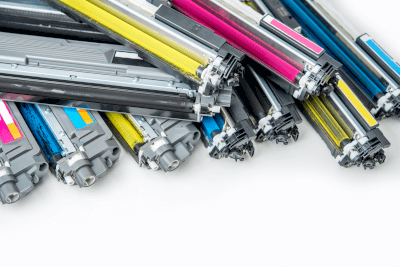
A copier toner is a powder used in laser printers and copiers. It is similar to hoe ink is used in printers.

There are two types of printer cartridges: ink cartridges and toner cartridges. Ink cartridges, used in inkjet printers, contain liquid ink made from pigments or dyes. This liquid ink can bleed unless printed on specific types of paper.

Toner cartridges, on the other hand, contain powdered resin (toner) with attached carbon or pigment, offering a non-bleeding print on various paper types.

Uses of Copier Toners

Copier toners are advantageous because they do not bleed and can be used on various paper types, including plain, recycled, and copier paper. This versatility helps reduce paper costs compared to liquid inks.

Additionally, laser printers using toners generally print faster than those using liquid ink. However, toners may not be as effective as liquid inks in reproducing vibrant colors and detailed images, such as photographs.

Principles of Copier Toners

Printing with copier toners involves six stages: charging, exposure, development, transfer, fixing, and cleaning.

The process begins with charging the photosensitive drum, which is then exposed to light (laser or LED) to create a latent image pattern. Toner, charged in the developer, adheres electrostatically to this latent image.

The toner is then transferred to paper, but as it is only resting on the surface, it requires fixing. This is achieved by melting the toner through heat or pressing it with pressure. The thermal roll method is a common fixing technique.

Thus, printing with toner relies on static electricity for adhesion and heat or pressure for fixation. The toner’s composition, including charge control agents and resin types, is crucial for managing these processes.

カテゴリー
category_usa

Urethane Spring

What Is a Urethane Spring?

Magnetic Chucks

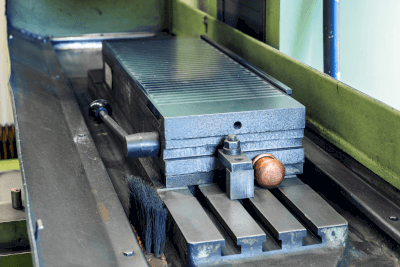
A urethane spring is a flexible component made of urethane, often used for its resilient properties. Typically crafted from molded urethane, these springs provide excellent shock absorption and cushioning, enhancing comfort and reducing the impact of vibration and shocks. Urethane’s lightweight nature also contributes to weight reduction in products, which is especially beneficial in transportation equipment such as vehicles and aircraft.

However, urethane is sensitive to high temperatures and may deteriorate under prolonged exposure. Special attention should be paid to high-temperature environments, like vehicle engine compartments. It’s also crucial to select the right hardness and thickness of urethane to avoid deformation under heavy loads.

Uses of Urethane Springs

Urethane springs have a wide range of applications, thanks to their cushioning and shock-absorbing properties. Key uses include:

1. Automobiles

These springs are used in automobile seats to provide comfort and reduce fatigue during long drives.

2. Furniture

Urethane springs are popular in furniture such as sofas and chairs for their comfort and durability and in mattresses and beds for body-conforming support and pressure dispersion.

3. Building Materials

They are used in buildings to enhance earthquake resistance and stability by absorbing vibrations from external sources like earthquakes and wind.

Principle of Urethane Springs

Urethane springs work based on the elastic properties of urethane. When external force is applied, urethane deforms and then returns to its original shape once the force is removed. This elasticity, coupled with vibration absorption properties, makes urethane springs effective for cushioning and shock absorption in various applications.

How to Select a Urethane Spring

When choosing a urethane spring, consider factors such as load, hardness, size, shape, comfort, and durability. The right selection depends on the specific application, whether it’s for comfort in furniture or durability in automobile suspensions.

カテゴリー
category_usa

Idler Pulley

What Is an Idler Pulley?

Idler Pulleys

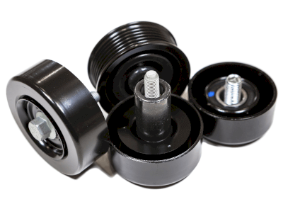
An idler pulley primarily guides V-belts, timing belts, and drive chains. It is responsible for restraining and positioning the belt within a machine. Various designations, such as idle gear, idle pulley, and idle wheel, are used to describe it.

“Idling” is a technical term in machinery, meaning “not in use” or “idle.” The “idler pulley” is named after this term, supporting the tensioner pulley that adjusts belt tension.

This article primarily discusses idler pulleys as automotive parts.

Uses of Idler Pulleys

Idler pulleys are commonly used in V-belts and timing belts, and are widely employed in automobiles and industrial machinery. In automobiles, these belts drive fans, air conditioners, and power steering systems and are involved in operating valves related to engine ignition. Tensioner pulleys adjust the tension of these belts, and idler pulleys are installed opposite the belt to reduce bouncing and flapping.

Features of Idler Pulleys

Idler pulleys are circular and contain an internal bearing. They have grooves on the outside for attaching a belt, allowing the installation of V-belts or timing belts. When drive torque is transmitted from the crankshaft through the belt, idler pulleys rotate, clamping the belt and transmitting torque to the camshaft.

Unlike tensioner pulleys, which adjust tension, idler pulleys do not have mounting holes for springs or slots in the bracket for position adjustment. They only feature a bearing for rotation and a groove for mounting the belt. Their primary function is to rotate in conjunction with the tensioner pulley.

However, the tensioner pulley alone can only secure the belt on one side. Therefore, the idler pulley is essential for clamping the belt from both sides.

As idler pulleys have built-in bearings, regular replacement is crucial to prevent sticking or seizure. In automobiles, it is recommended to replace idler pulleys along with the V-belt and timing belt after a certain mileage, such as 100,000 km.

カテゴリー
category_usa

U Bolt

What Is a U Bolt?

U Bolts

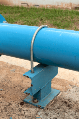
A U bolt is a fastening device commonly used in plumbing to secure piping or tubing. Characterized by its U-shape, it is typically threaded at both ends, allowing it to clamp onto pipes or tubes effectively. This design ensures the pipes or tubes are held firmly in place, preventing movement or shifting.

While U bolts are straightforward to install, care is needed in environments with vibration. To prevent loosening or shifting, appropriate vibration-absorbing materials, nuts, or additional vibration countermeasures should be used.

Uses of U Bolts

U bolts have a wide range of applications, particularly in:

1. Piping Installation

They are used to secure piping to walls and floors in buildings and factories, providing stability and reinforcement at specific points or junctions.

2. Hanging Piping

U bolts are also employed for suspending long pipes and tubes from ceilings and beams, ensuring stable support.

3. Vibration Control

In vibration-prone environments, U bolts play a critical role in preventing misalignment and loosening, often used with vibration absorbers and cushioning materials.

Principle of U bolts

The effectiveness of U bolts lies in their U-shaped geometry and the mechanical properties of their threads. The U shape allows the bolt to encircle a pipe, providing stability, while the threaded ends can be tightened to secure the pipe firmly. Applying the correct torque ensures the U bolt clamps the piping securely.

U bolts are typically made of materials like SS400 with zinc plating or SUS, and are compatible with various piping materials.

How to Select U Bolts

Key considerations when choosing a U bolt include:

1. Pipe Size

Measure the outside diameter of the pipe accurately to ensure a snug fit with the U bolt’s inside U-shaped portion.

2. Load

Choose a U bolt that can handle the load and environmental conditions where it will be used. Heavy loads and harsh conditions require stronger materials.

3. Environmental Conditions

Consider the material and anti-corrosion treatment of the U bolt, especially in humid or corrosive environments.

Other Information on U Bolts

How to Use U Bolts

While hanging bands and other methods are available for fixing piping, U bolts are preferred for heavy piping or in environments with vibration. However, caution is advised when fastening plastic piping or heat-expanding pipes like steam piping. Additionally, using steel U bolts on SUS supports and piping may lead to dissimilar metal corrosion.

カテゴリー
category_usa

Boring Bar

What Is a Boring Bar?

A boring bar is a specialized tool used in machining to perform boring operations, which involve enlarging a pre-drilled hole to precise dimensions with high accuracy and smoothness. It typically comprises a single-blade tool and a dimensional adjustment screw, offering enhanced precision and roundness compared to other hole-finishing methods.

Uses of Boring Bars

Boring bars are essential for creating precision holes, especially in industrial products like engine and transmission joints or gear holes. They are favored for machining holes with tight tolerances (H7 and H6), ensuring superior surface roughness and roundness compared to end mills.

Principle of Boring Bars

The tool features an insert-replaceable blade and an adjustment screw for dimensional fine-tuning. Proper adjustment is crucial to match the pre-drilled hole size before machining, with careful programming needed to avoid surface imperfections during the machining process.

Types of Boring Bars

Boring bars are categorized based on the material and application:

1. High-Speed Boring Bars

Best suited for roughing operations and finishing holes larger than 15 mm in diameter with general tolerances.

2. Tungsten Carbide Boring Bars

These are harder than high-speed steel (HSS) and are preferred for precision machining of holes 15 mm in diameter or smaller. They offer long-term cost benefits due to their durability and time efficiency, despite higher initial costs and brittleness.

Other Information on Boring Bars

Adjusting Boring Bars

Adjustment involves turning the built-in screw to alter the tool’s dimension, with digital and analog scale options available. Despite the convenience of digital scales, both types require careful calibration to ensure accuracy.