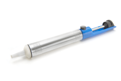
カテゴリー
category_usa

Centrifuge Tubes

What Is a Centrifuge Tube?

Centrifuge Tubes

Centrifuge tubes, also known as stitches, are containers used in experiments and tests in which liquids are separated from each other or solids and liquids are separated using a centrifuge.

Glass or plastic is used as the material, and you can choose one that is resistant to impact and strength, one that is cold- or heat-resistant and suitable for temperature changes, or one that is chemical-resistant, depending on the intended use.

There are also those with scales, those that can be written on the container, and those with a tight-sealing cap.

Uses of Centrifuge Tubes

1. Use With Centrifuges

A centrifuge is used to collect insoluble substances as precipitates by centrifuging a suspended sample in a centrifuge tube, which has the shape shown in Figure 1. The centrifuge is a device that rotates a rotor, to which the centrifuge tube can be set, at high speed. Centrifugal force can separate liquids and solids, or liquids with different specific gravities.

2. Use for Sample Collection and Preservation

Centrifuge tubes with a screw-type cap structure are sometimes used to collect, transport, and store samples that require delicate handling due to their excellent sealing and preservation properties.

In the field of biochemical experiments, they are also used to separate cells collected as precipitates by centrifugation or to extract nucleic acids from cells and can be used to preserve and fine-tune each component.

Characteristics and Principles of Centrifugation Using a Centrifuge Tube

1. Separation of Liquid Components With Different Specific Gravities

Centrifugal separation is the separation of substances with different specific gravities by centrifugal force. The centrifugal force generated by high-speed rotation can reduce the time required for the sedimentation of substances that would otherwise take a long time to settle naturally. Since liquid components with heavier specific gravity settle faster than those with lighter specific gravity, multiple liquid components with different specific gravity can be separated as liquid phases in a centrifuge tube according to their specific gravity.

2. Separation of Insoluble Material From Suspension

When a substance is dispersed in a liquid without dissolving, it is called a suspension. To separate insoluble components from such a sample, the suspension is injected into a centrifuge tube and subjected to centrifugal separation, where only the insoluble components are obtained as precipitates. Therefore, this method is used to recover minute amounts of fine insoluble substances contained in the suspension. For example, in experiments using microorganisms or cells, it is used to separate only the cells from the culture medium.

3. Emulsion Separation

A liquid in a state of dispersion of immiscible liquids such as water and oil is called an emulsion. Familiar examples include milk and mayonnaise. Centrifugal separation is also used to separate each liquid component from such liquids.

Structural Features of Centrifuge Tubes

1. Strength

The main uses of centrifuge tubes are to seal the sample inside the tube and to use it as a container to set the sample in a centrifuge, which involves strong physical stimulation. Therefore, the centrifuge tube has a structure that can withstand centrifugal force, is hermetically sealed, and has excellent strength to prevent cracking even under load.

2. Shape

The centrifuge tube has a narrow tip to allow insoluble components to precipitate at high density and in a narrow surface area. Thanks to this unique shape, insoluble components can be efficiently collected at the bottom of the centrifuge tube. There are various types of centrifuge tubes on the market, some of which have scales engraved on the tube or are made of a material that is easy to write on the sides or cap to prevent the scales from disappearing due to rubbing, etc. Some of them have scales engraved on the tube molding.

カテゴリー
category_usa

Pusher

What Is a Pusher?

A pusher is a mechanical device designed to exert a pushing force on objects. This device is particularly beneficial in situations where human strength is insufficient for moving heavy items or when precise and consistent pressure application is necessary.

Pushers are integral to automated processes, enhancing efficiency and accuracy in various industries by mechanically executing programmed movements. However, their operation requires skilled personnel to ensure safety and effectiveness.

Uses of Pushers

Pushers find their application in numerous settings:

1. Automated Equipment

In automated manufacturing lines, pushers accurately position parts during assembly, crucial in industries like automobile manufacturing for precision-oriented tasks.

2. Door Mechanisms

They play a vital role in the automatic opening and closing systems of doors and elevators, responding to sensor inputs to operate the doors.

3. Construction Equipment

On construction sites, pushers, mounted on heavy machinery like bulldozers, move materials and level terrain, surpassing the efficiency achievable by manual labor.

4. Gaming Machines

In amusement facilities, pushers are used in coin pusher games to nudge coins and prizes, adding an element of challenge and excitement to the game.

Principle of Pushers

The fundamental principle of pushers lies in their ability to apply mechanical force, sourced from electricity, hydraulics, pneumatics, or manually. This force is transmitted to an operating component, such as a link, piston, rod, or plate, which directly interacts with the object to be moved.

Various pusher designs exist, such as hydraulic pushers that use cylinders to amplify force, and electric pushers that employ motors or gear mechanisms for force transmission.

How to Select Pushers

Selection of a suitable pusher involves:

1. Defining the application: Different pushers suit different tasks, from manufacturing line operations to construction site activities.

2. Considering capacity: Choose a pusher that can handle the size, shape, and weight of the object without exceeding its capabilities.

3. Power source: Select a power source (electricity, pneumatics, etc.) that aligns with the operating environment and work requirements.

カテゴリー
category_usa

Desoldering Equipment

What Is Desoldering Equipment?

Desoldering Equipment

Desoldering equipment is a tool designed for removing misplaced solder from electronic components and circuit boards. Solder, a vital material in electronic assembly, occasionally ends up in the wrong places due to operational errors. Desoldering tools provide a solution to this problem by enabling the removal and reuse of solder, thereby reducing waste and costs.

While these tools enhance work efficiency and productivity, they often use heat for solder removal, which can potentially damage heat-sensitive components or circuit boards if not used carefully.

Uses of Desoldering Equipment

Desoldering tools are versatile and find application in various soldering tasks:

1. Correcting Misplaced Solder

They are primarily used to rectify soldering mistakes, ensuring accuracy in the assembly process.

2. Solder Removal

Desoldering tools are instrumental in removing old solder from circuit boards and components and preparing them for reuse or recycling.

3. Solder Transfer

These tools can transfer solder precisely to specific locations, assisting in complex soldering tasks.

4. Cleaning

They also serve to clean the surfaces of circuit boards and electronic components from accumulated dirt and debris.

Principle of Desoldering Equipment

Desoldering equipment operates by combining heat and suction. The tool’s tip is heated to melt the solder, turning it into a liquid state. A suction mechanism, typically a pump or fan, then draws the molten solder into the tool. As the solder cools, it solidifies and collects in a compartment for later disposal or reuse.

How to Select Desoldering Equipment

Choosing the right desoldering tool involves considering factors such as power source, cylinder capacity, heat source, and anti-static measures:

1. Power Source

Options include manual tools, which rely on physical force for suction, and electric tools that offer ease of use with power-generated suction.

2. Cylinder Capacity

The cylinder capacity determines the volume of solder the tool can handle, which should align with the user’s needs.

3. Heat Source

Tools come with built-in heating elements or require separate heat sources. The choice depends on the specific requirements of the task at hand.

4. Anti-static Measures

For electronic applications, selecting tools with anti-static features is crucial to protect sensitive components from static damage.

カテゴリー
category_usa

Chemical Protective Clothing

What Is Chemical Protective Clothing?

Figure 1. Overview of protective clothing

Figure 1. Overview of protective clothing

Chemical protective clothing is protective clothing worn to ensure the safety of workers and protect their health when handling hazardous chemical substances.

Protective clothing should be worn when engaged in work involving the handling of acids, alkalis, organic chemicals, and other gaseous, liquid, and particulate chemical substances (hereinafter referred to as chemical substances).

Unlike ordinary clothing, the surface gaps are very small and smooth. The materials used also have extremely low permeability to organic solvents. Although originally manufactured to protect against chemical substances, it is also used to protect against biological and radioactive materials due to its high particulate protection effectiveness.

Uses of Chemical Protective Clothing

The main uses of chemical protective clothing are in workplaces where chemical substances are handled, in the event of a disaster caused by nuclear, biological, or chemical substances, and in workplaces where hazardous substances must be disposed of.

Examples of past large-scale disasters include the following:

  • Investigating chemical attacks
  • Asbestos treatment work
  • Dioxin and PCB treatment work
  • Disinfection and dismantling of chicken coops contaminated with avian influenza

Chemical protective clothing is usually used to protect against harmful substances to the human body, but it can also be used to protect workers from contamination.

Examples include metalworking industries where grease and soot stains are common, and painting and printing industries where paint and ink are used.

Other applications include clean rooms in regenerative medicine research, where protective clothing is used to protect cells and drug products from bacteria that may be attached to the worker’s body.

Principle of Chemical Protective Clothing

Figure 2. Various materials used in protective clothing

Figure 2. Various materials used in protective clothing

Chemical protective clothing is made of a variety of textile materials, including non-woven fabrics, SMS, FS, and Tyvek®. It is very important to wear protective clothing of the appropriate standard for the intended event.

1. One-Layer Non-Woven Fabric Type

This product is made of spunbond polypropylene. The single-layer structure of spunbonded polypropylene fabrics allows for a large number of voids between fibers. Although the barrier property is somewhat inferior, it is inexpensive and suitable when cost is important. It is sufficient for light soiling.

2. SMS

SMS polypropylene is used for this product. It has a three-layer structure consisting of spunbonded, meltblown, and spunbonded materials. It is characterized by strong abrasion resistance and a cloth-like feel. Although relatively inexpensive, it is resistant to abrasion and light soiling, and has a high barrier effect against dust and droplets.

3. FS

This product uses a film laminate. It has a structure in which a thin film material is attached to the surface of polypropylene, spun-bonded nonwoven fabric, or the like. It has high barrier properties against dirt and dust, and excellent waterproofing properties, making it suitable for work in watery areas.

4. Tyvek

Tyvek is a special material unique to DuPont, consisting of continuous microfibers of high-density polyethylene (0.5~10 microns) bonded together by heat and pressure, which provides excellent barrier properties against particles of 1 micron or less. Two-layer protective clothing with polymer coating is also available.

Types of Chemical Protective Clothing

Figure 3. Full Body Chemical Protective Clothing and Partial Chemical Protective Clothing

Figure 3. Full Body Chemical Protective Clothing and Partial Chemical Protective Clothing

There are two types of chemical protective clothing: full body chemical protective clothing, which protects the entire body or a large part of the body, and partial body chemical protective clothing, which protects a part of the body.

Full-body chemical protective clothing can range from airtight suits with self-contained breathing apparatuses inside, to full-body suits that are sealed against liquids and chemical mists.

Partial chemical protective clothing includes aprons, footwear covers, lab coats, arm covers, and smogs.

カテゴリー
category_usa

Hexagon Nuts

What Is a Hexagon Nut?

Hexagon NutsHexagon Nuts are a fastening part with a hexagonal outer shape and a threaded center hole. Generally, Hexagon Nuts are not used by themselves, but are inserted between parts to be fastened, and screwed into threaded parts such as bolts.

ISO Standard

  • ISO 4032:2012 Hexagon regular nuts (style 1) – Product grades A and B
  • ISO 4033:2012 Hexagon high nuts (style 2) – Product grades A and B
  • ISO 4034:2012 Hexagon regular nuts (style 1) – Product grade C
  • ISO 4035:2012 Hexagon thin nuts chamfered (style 0) – Product grades A and B
  • ISO 4036:2012 Hexagon thin nuts unchamfered (style 0) – Product grade B
  • ISO 8673:2012 Hexagon regular nuts (style 1) with metric fine pitch thread – Product grades A and B
  • ISO 8674:2012 Hexagon high nuts (style 2) with metric fine pitch thread – Product grades A and B
  • ISO 8675:2012 Hexagon thin nuts chamfered (style 0) with metric fine pitch thread – Product grades A and B

Principles of Hexagon Nut

Hexagon Nuts tighten and secure parts using the threaded fastening principle. By turning the hexagon nut, the nut and bolt contact the part to be fastened, and then tightening the nut further, the following forces are exerted.

  • Compressive force (force that pushes in the direction of the axis of the clamp) on the part to be clamped
  • Tensile force (reaction force of the part to be fastened) on a screw such as a bolt

As a result, the following frictional forces are generated and the screw remains tightened without loosening.

  • Between the male thread and female thread
  • Seat surface of the bolt and nut (surface in contact with the part to be fastened)

Uses of Hexagon Nuts

Nuts come in a variety of shapes and types, but hexagonal nuts, in particular, are probably the most commonly used for fastening parts.

Hexagon Nuts are used in a very wide variety of situations, from general purpose to special applications, from very small parts to large parts, from very small parts such as precision instruments to household DIY, railroad tracks, and general industrial equipment and facilities.

Hexagon Nuts are characterized by their hexagonal shape, which allows tools such as wrenches and wrenches to be hung on them at 60-degree intervals, allowing them to be tightened at small angles. They are also very easy to use since many general-purpose tools are compatible with them.

Types of Hexagon Nuts

There are a wide variety of locks that have anti-loosening functions, and their respective functions and features must be used effectively. In addition to the above, there are many other types of products, including standard products, special-purpose and specially designed products.

How to Use Hexagon Nuts

If Hexagon Nuts are not used properly, the bolts on the mating side may be damaged, or products or equipment assembled with hexagon nuts may be damaged.

To prevent this, the following points must be observed:

  • Tightening force must be within the allowable range to prevent damage to the hexagon nut and bolt.
  • Repeated forces (e.g., vibration) applied to the hexagon nut and bolt must be within the allowable range.
  • The seating surfaces of the hexagon nut and bolt (the surfaces that come into contact with each other, not the surfaces that the tool touches) must be within the allowable range. The seating surfaces of the hexagon nut and bolt (the surfaces that contact each other, not the surfaces that the tool touches) must not cause the object to be tightened (metal, wood, etc.) to cave in.
  • Tightening the hexagon nut and bolt must not damage the object to be tightened.

Other Information on Hexagon Nut

1. Material and Surface Treatment of Hexagon Nut

Hexagon Nut materials, mainly iron, alloy steel, stainless steel, titanium alloy, copper and copper alloy, aluminum and aluminum alloy, nickel alloy, etc. Generally, materials are selected according to requirements such as strength and corrosion protection.

When a bolt or nut is subjected to a heavy load or used in equipment where human life may be at stake, the material of the hexagon nut has a significant impact on its strength, so it is necessary to select a material with sufficient strength requirements.

The presence or absence of measures against corrosive environments is also an important factor in material selection. Material selection should be based on the corrosive environment so that the hexagon nut does not lose weight and strength due to corrosion.

Electrical corrosion is also an important factor. If the material of the hexagon nut differs from the material of the mating mechanical element or the object to be fixed, a difference in metal potential may result in corrosion. Particular attention should be paid in the case of aluminum and stainless steel.

The following surface treatments are available for hexagon nuts, which are selected according to appearance quality and price:

Electroless nickel, trivalent chromate, unichromate plating, zinc plating, chromate plating, nickel plating, chrome plating, parker, dacrotized, paint/coating, silver, copper, tin plating, etc.

2. Preventing Hexagon Nuts From Loosening

The following measures can be taken to prevent loosening of hexagon nuts:

Initial loosening measures
A spring washer or disc spring washer is inserted between the hexagon nut and the part to be fastened. This function compensates for the initial reduction in axial force and has no effect on preventing slippage of the seating surface, thus it cannot prevent loosening due to the nut’s return rotation.

Countermeasure against reduction in axial force (non-return stop)

  • Mechanical anti-rotation method
    To prevent the nut from turning, the following parts are used to secure the nut to the threaded side.
    Example: grooved lock nut + split pin, lock nut with external teeth, wire lock, etc.
  • Incremental return torque method
    This method increases the resistance to rotation between the male and female threads in order to prevent loosening by using the following parts.
    Example: Nylon insert locknut, ring locknut, flex locknut (slit nut), flange nut (with serration), etc.
  • Return Rotation Prevention (Loosening Prevention)
    1. This method increases friction between the male and female threads to prevent the nut from rotating back. Double nuts are applicable.
    2. This method applies an adhesive or other substance to the threaded part to adhere it. Anaerobic adhesive application, screws with adhesive, etc. fall under this category.
    3. This method uses two types of nuts with eccentric, wedge-shaped concavities and convexities. The entire thread of the convex nut is pressed against the bolt side, and the entire thread of the concave nut is pressed against the threaded portion of the bolt on the opposite side. The “wedge” effect is utilized. Hard locknuts fall into this category.
カテゴリー
category_usa

Graduated Cylinders

What Is a Graduated Cylinder?

Graduated Cylinders
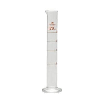
A graduated cylinder is a laboratory instrument used to measure the volume of a liquid. It is cylindrical, and equipped with a scale on the side. The volume is read visually at the lowest point of the meniscus, which forms at the surface of the liquid in the cylinder.

It’s important to avoid using abrasive materials for cleaning the cylinder as they can scratch the interior, leading to minor volume discrepancies.

For measuring organic solvents, it’s advised to use a glass cylinder, as plastic ones can dissolve or swell due to certain solvents. A glass cylinder is recommended in such cases.

Uses of Graduated Cylinders

A graduated cylinder is a laboratory instrument used to measure the volume of liquids in chemistry experiments. They are also a staple in educational settings for simple, hands-on science experiments.

The capacity of graduated cylinders typically ranges from 10 mL to 1 L. The volume per scale division and the associated measurement error vary depending on the cylinder’s capacity. The material of the cylinder is glass or resin.

Usage and Accuracy of Graduated Cylinders

A graduated cylinder is an elongated cylindrical container with a scale on it. To ensure an accurate reading, place the cylinder on a level surface and observe the scale at the meniscus’s bottom.

The accuracy of the graduated cylinder is determined by the fineness of the scale. For precise measurements requiring higher accuracy, a volumetric flask is recommended over a graduated cylinder. See more on measuring flasks.

How to Clean a Graduated Cylinder

Clean it using a solvent that can dissolve the contents or residue. Avoid abrasive materials during cleaning to prevent scratching the glass, which could affect volume measurements.

For resin cylinders, use water or a solvent that is chemically compatible with the resin to prevent alterations in volume due to swelling or dissolution. Cleaning with organic solvents such as acetone may cause volume changes in resin cylinders.

カテゴリー
category_usa

Burets

What Is a Buret?

Burets

A buret is a glassware that can measure the volume of liquid dropped by dropping a small amount of liquid while operating it with a cock.

A removable cock is attached to the bottom of a thin, tubular glass tube with a scale on it, and the amount of liquid dropped is adjusted by turning the cock.

A pipette can also be used to measure the volume of a dropped liquid, but the buret can be used in a vertical position, so the scale can be read more precisely and the amount of liquid can be adjusted finely with the cock. Moreover, since the volume of a drop can be precisely controlled with a cock, the buret is suitable for experiments that require accurate liquid volume measurement, such as neutralization titration.

Uses for burets

Buret is mainly used for neutralization titration. Neutralization titration is a type of volumetric analysis, in which the concentration of a solution of unknown concentration is determined using a standard solution of known concentration and a solution of unknown concentration that reacts in proportion to the concentration of the standard solution.

The judgment of the neutralization reaction, the so-called endpoint, is determined by the color change of the mixed solution after dropping. Although the operation of the cock requires a certain degree of skill, an automatic operation called auto-buret is also available and is used for quality control in the food, pharmaceutical, and chemical industries.

Features of burets

Burets are available in white and brown. As with other glassware, some substances react with light, so the choice should be made according to the type of substance dissolved in the standard solution. For example, silver nitrate is photosensitive and must be used under a light-shielded condition, so a brown buret must be used when using it as a titrant.

Also, as mentioned above, it is important to become familiar with the buret’s cocking operation. If the speed of dropping liquid from the buret is too fast, there is a possibility of adding more standard solution than the endpoint. In addition, it is necessary to grease the cock part for maintenance, and if maintenance is insufficient, liquid may leak, etc.

Furthermore, if the tip is chipped, it is impossible to accurately measure the volume, so it must be handled with care. Experiments have shown that even a scratch on the tip can change the volume per drop. It is also known that the volume of residual liquid in the buret changes the volume of the residual drop, so it is advisable to always use the buret from the top of the scale, which is the zero point.

Since the buret is glassware, repeated heating and cooling deforms it, which impairs the accuracy of its measurement volume. Therefore, heating and drying after washing should be avoided, and the buret should be dried at room temperature. For the same reason, the titrant to be placed in the buret should be a liquid with a constant temperature of about room temperature. The temperature of the titrant should be considered not only because it causes expansion and deformation of the buret, but also because the volume of the titrant is temperature-dependent. For this reason, the titrant should be at a constant temperature for accurate volume measurement.

Why co-wash a buret?

Co-washing is the process of washing a buret, a whole pipette, or another side vessel instrument (an instrument used to measure the volume of a liquid) with the solution to be weighed (the solution to be placed inside).

To avoid volume changes due to deformation of the instrument, side vessel instruments are usually not heated and dried in a dryer. After washing with tap water, they are rinsed with distilled water and washed with the solution to be weighed immediately before use.

The reason for co-washing is that the concentration of the sample solution decreases when the inner surface of the instrument is wet with water. On the other hand, if the sample solution itself is wet, the concentration does not change when the solution is added.

Since a buret is used to put in a solution of unknown concentration during titration, if the concentration of the solution changes inside the buret, it will be impossible to obtain an accurate concentration.

Also, if you co-wash the apparatus once used again, you can continue to use it without letting it dry out.

First, fill the buret about 1/5 of the way with a solution and wash the inner walls while turning the buret on its side. Next, turn the cock to let the solution out of the tip, wash the inner wall below the cock, and discard the remaining solution from the top. This process is repeated several times. 

How to use the buret

Fix the buret vertically to the buret stand and make sure the live plug is closed.

Using a funnel, pour the solution from the top of the glass tube. To prevent the solution from overflowing from the top of the funnel, leave a gap between the funnel and the top of the buret to allow air to escape. Also, to prevent the solution from getting into the eyes, pour the solution below eye level. After pouring the solution, remove the funnel.

Open the stopper with a beaker or other container underneath, and pour out the solution vigorously to completely expel air bubbles from the area below the stopper. If there are air bubbles above the stopper, remove them as well.

After the air has been expelled, read the scale and record the reading. The bottom (lower end) of the “meniscus” should be read, with the buret perpendicular to the line of sight. The meniscus is the curved surface of the liquid in a narrow tube due to surface tension, or a dent if the liquid wets the tube wall. The scale is read by eye to the nearest 1/10 of the smallest scale.

Turn the stopper to start dripping. Hold the buret with one hand and pull it toward the main body of the buret to prevent the stopper from falling out.

When titration is completed, read the scale to determine the volume to be titrated.

カテゴリー
category_usa

Cable Glands

What Is a Cable Gland?

Cable Glands

Cable glands, essential in electrical systems, are devices used to insert and securely fasten electrical cables into control panels and operation panel enclosures and equipment.

The main functions of a cable gland are as follows:

External environmental protection: Prevents dust, dirt, and moisture from entering through openings in enclosures such as control panels.
Retention: Securely holds cables in place and prevents them from loosening under external mechanical tension or vibration.
Sealing: Prevents dust and water from entering the cable from the outside.

JIS F8801 “Marine Wire Penetration Hardware” is the standard for cable glands.

Uses of Cable Glands

Cable glands, vital for ensuring safe and secure cable connections, are used to penetrate enclosure walls by attaching to cable intakes in devices like control panels. They are crucial in both indoor and outdoor wiring setups of electrical and control equipment.

These glands protect against dust and water ingress in control and operation panel enclosures, mitigate disconnection risks from vibrations or pulling, and ensure secure cable fastening and management.

Available in various materials like stainless steel and polyamide resin (PA), selecting a cable gland suitable for specific environments—such as outdoor, oily, or high-temperature conditions—is critical for optimal performance.

Alongside cable glands, cable clamps are also used for introducing cables into enclosures. While cable glands are typically employed for single cable entries, a ground clamp is more suited for multiple cable installations.


カテゴリー
category_usa

High Voltage Transformers

What Is a High Voltage Transformer?

High Voltage Transformers
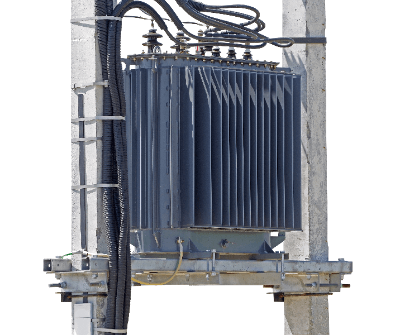
A high voltage transformer is a transformer that inputs high voltage as a primary voltage and outputs a stepped-down or stepped-up secondary voltage.

A transformer is a device that converts the voltage of an input current to another voltage for output. Converting to a lower voltage than the input voltage is called step-down, and conversely, converting to a higher voltage is called step-up. There are three types of power supply voltage standards: low voltage, high voltage, and special high voltage.

Uses of High Voltage Transformers

High voltage transformers are generally used to supply power to large facilities with high power consumption, such as factories, hospitals, and commercial facilities.

Electricity generated at power plants is very high voltage, tens of thousands of volts. This power cannot be used if it is transmitted directly to users. However, from the standpoint of transmission efficiency, the power is transmitted at high voltage and low current in the vicinity of the supplier, and then stepped down to a voltage that can be used by a high-voltage transformer.

High voltage transformers are generally built into high voltage receiving facilities called cubicles and placed on rooftops.

Principle of High Voltage Transformers

A transformer consists of two coils. The two coils are electrically separated but magnetically connected by an iron core.

The coil on the input side is the primary coil and the output side is the secondary coil. When a current flows through the primary coil, a magnetic flux is generated based on Ampere’s law. This magnetic flux is transmitted through the iron core to the secondary coil, and based on Faraday’s law of electromagnetic induction, a voltage corresponding to the number of turns of the coil is generated. Thus, by using the coil and iron core, it is possible to convert the voltage between the input and output power sources.

Other Information on High Voltage Transformers

1. Cooling System of High Voltage Transformer

Since heat is generated inside the transformer due to power loss, a cooling system is introduced. There are two types of cooling methods: the “oil-filled method” in which the windings are cooled with insulating oil, and the “molded method” in which no oil is used.

Since high voltage transformers are used in facilities where strict disaster prevention measures are required, the “molded type” is often adopted because of its low fire risk. In the case of oil-filled transformers, Class 3 petroleum is used for the insulating oil. Note that as the capacity of the high voltage transformer increases and the amount of oil exceeds 400 L, the oil by itself is considered a hazardous material.

Also, as the capacity increases, it becomes more difficult to use self-cooling transformers, so the forced circulation type is used.

2. Price of High Voltage Transformers

High voltage transformers are relatively inexpensive among industrial equipment because of their simple mechanism. For a transformer with a typical temporary voltage of 6,600V/3,300V and a secondary voltage of 400V/200V/105V, catalog products are available from various heavy electric appliance companies.

Catalog products are considered having an upper limit of around 2,000 kVA, and anything above that is made-to-order. The average price of an oil-filled, self-cooling transformer is several hundred thousand yen for a transformer of several tens of kVA, and several million to 20 million yen for a transformer of 2,000 kVA (as of 2021). Molded systems are more expensive.

The above prices are for general step-down transformers, but those with special specifications are made-to-order, so consultation with heavy electric machinery companies is required for pricing. 

3.High Voltage Transformer Capacity

The capacity of a high voltage transformer is determined by the allowable current value of the windings and the capacity of the magnetic iron core. If a current exceeding the allowable value flows through the windings, the transformer is protected by an overcurrent relay to prevent burnout.

The capacity of a three-phase motor, for example, is measured in kilowatts (kW), whereas the capacity of a high voltage Transformer is measured in kilovolts (kVA). Catalog products of single-phase, three-wire High Voltage Transformers have an upper limit around 300 kVA, while three-phase 400 V/200 V transformers have an upper limit of 2,000 kVA.

In the case of a cubicle type, the upper limit for commercial products is around 750 kVA due to the size of the enclosure and cooling capacity. 

4. Power Factor of High Voltage Transformers

It is important to note that the amount of work applied to a high voltage transformer varies depending on the power factor of the load. The further the power factor is from 1, the less work can be applied. By keeping the power factor of the secondary side of the high voltage Transformer at 1, the high voltage transformer can be used to its capacity without waste.

Since industrial machinery has many motors, the power factor often swings in the lagging direction. As a general measure, a power capacitor is connected in parallel with the load to compensate.

High voltage transformers are designed for maximum efficiency at around 60% load. Therefore, it is important to select a capacitor with a generous margin so that the normally used capacity will be around 60%.

カテゴリー
category_usa

Surge Absorbers

What Is a Surge Absorber?

A Surge Absorber is a device that protects equipment from surge voltage.

Surge voltage is a high voltage that rises steeply, and a typical example is the lightning surge voltage caused by a lightning strikes. Surge voltages are generated not only by lightning, but also by switching of high power conductors and static electricity.

Equipment connected to a circuit where surge voltage is generated is at risk of damage due to insulation breakdown. A device that absorbs surge voltage is called a surge absorber.

In other words, it is a device that protects equipment from momentary abnormal voltage.

Usage of Surge Absorbers

There are two types of surge absorbers, one for power circuits and the other for control circuits. Surge absorbers for power circuits are classified into two categories: lightning protection and switching surge voltage absorption.

Surge absorbers for lightning protection are used on utility poles, etc., to release abnormal voltage to the earth in the event of a lightning strike. In this application, they are also called “surge arresters“.

Surge Absorbers for open/close surge voltage absorption are used in high-voltage panels.

Surge Absorbers for control circuits are used in LAN circuits and telephone circuits. The main purpose is to protect office automation equipment and precision control equipment from lightning strikes, etc.

In addition to office automation equipment, surge absorbers are used to protect telephones, fax machines, modems, TV antennas, displays, and car navigation systems.

Principle of Surge Absorber

Surge Absorbers are devices that disconnect surge voltage from the main circuit. There are two main types of surge absorbers: those that absorb surge voltages due to ground faults and those that absorb surge voltages due to resistance.

The ground-fault type absorbs only abnormal voltages by means of semiconductors or discharge tubes. This type is used for equipment that may be subject to lightning strikes. The type that absorbs by resistance absorbs abnormal voltages using coils and resistors. Surge absorbers are mainly used to absorb surge voltages other than those caused by lightning strikes.

Types of Surge Absorbers

There are several types of Surge Absorbers. The principle and characteristics differ depending on the type.

1. ZnO Type Surge Absorber

The ZnO type surge absorber is the most common type of used for lightning surges. Zinc Oxide (ZnO) is a type of semiconductor with low resistance to high voltage.

Grounding a circuit through ZnO allows surge voltages to escape to the earth in the event of an abnormality. It is used in a wide range of circuits from small to large capacitance circuits.

2. CR Type Surge Absorber

A capacitor or resistor is installed in parallel with the circuit to be protected. The capacitor acts to protect the circuit by passing current through the resistor in the event of an abnormally high voltage. They are mainly used in small-capacity circuits and are sometimes called surge killers. 

3. Diode Type Surge Absorber

A diode is installed in parallel with the circuit to be protected, and the rectifying action of the diode absorbs the surge voltage. They can only be used in DC circuits and are used in circuits with relatively small capacitance.

4. Surge Absorber With Discharge Tube

A grounded discharge tube is built into the circuit to release high voltages to the earth. The inside of the tube is filled with inert gas, and the operating voltage is adjusted according to the gap in the tube. While large-capacity discharges are possible, there is a disadvantage of slow operation speed.

In addition to the above, there are surge absorbers that use thyristors for grounding. Surge absorbers act as a device that does not exist in the circuit during normal operation when no surges are present. When a surge enters the circuit, the surge absorber quickly absorbs the surge current and protects the circuit.

In practice, however, surge absorbers inevitably have a delay before they react. The longer the delay time, the more damage is caused to the circuit; surge absorbers using semiconductors such as ZnO type have a feature of short delay time. For this reason, ZnO type surge absorbers are the most common type of surge absorber today.

Today’s precision equipment is becoming more and more vulnerable to surges as it becomes more sophisticated and compact. Thyristors and ZnO elements also have large capacitance, and there is a danger of distorting the waveform of weak electric circuits, so they must be incorporated with consideration.