Control Panels

What Is a Control Panel?

Control Panels
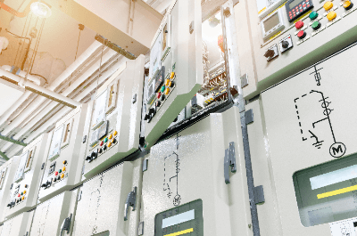
A control panel is a box in which electrical equipment for controlling industrial production lines and machinery is concentrated.

It is generally manufactured in the form of a robust metal box, and is baked or powder coated to prevent rust, corrosion, and salt damage.

Uses of Control Panels

Control panels are used in all aspects of industry.

The following are applications of control panels:

  • Operation control of pumps for industrial wastewater
  • Operation and control of water supply pumps
  • Control and operation of product transfer equipment
  • Operation and control of elevators
  • For operation of product processing equipment

Control panels are used to control production lines and machinery. A control panel is a complete set of machine control equipment housed in a control panel cabinet for the purpose of protecting it from the outside environment.

In everyday life, you may see control panels for controlling infrastructure equipment such as water and sewage pumps around town.

Principle of Control Panel

A control panel consists of a control panel cabinet, protection and drive units, control units, etc.

1. Control Panel Cabinet

The control panel cabinet is the outer box of the control panel. It is mainly made of steel and fitted with a door with a handle on the front. A grounding terminal is attached at the bottom and is connected to the grounding pole by a wire for grounding. In addition, indicator lights and display meters may be attached to the panel door to indicate the status of the machinery and equipment to be controlled.

2. Protection and Drive Equipment

Protection and drive devices are power components that operate electric machines. Circuit breakers and ground-fault relays are protective devices that sound an alarm or safely shut off the circuit in the event of a short circuit or ground fault. Electromagnetic switches, inverters, servo amplifiers, etc. are driving devices that supply electric power to drive electric machines.

3. Control Devices

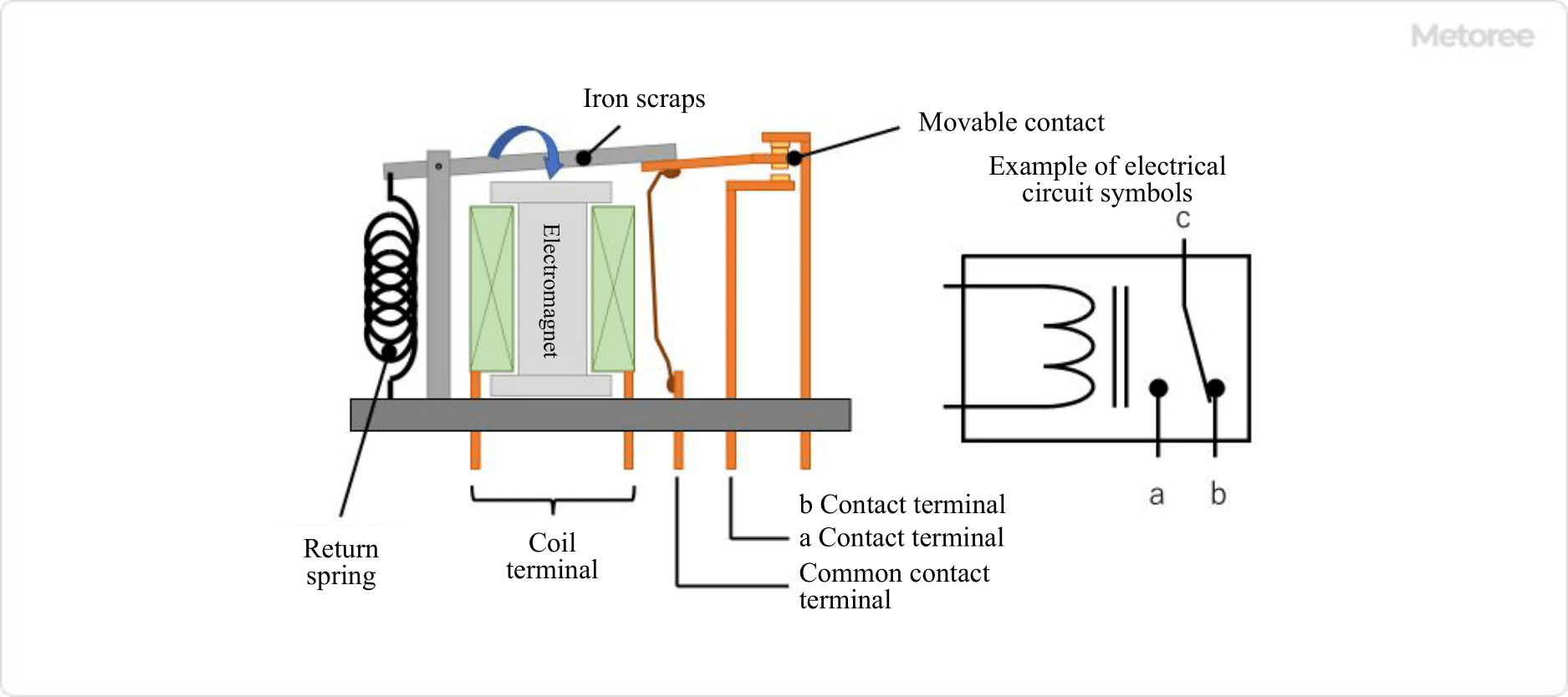
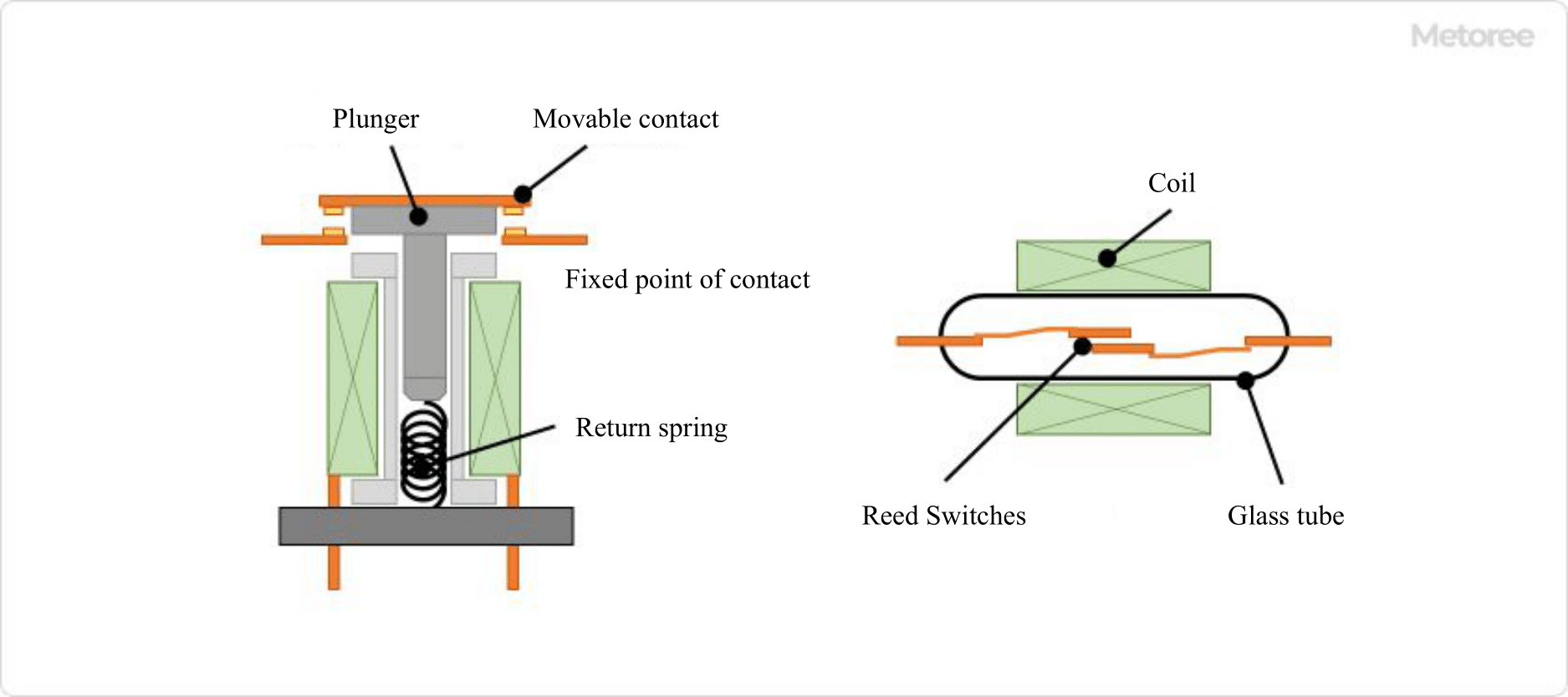
Control devices are instrumentation components that control electric machines. Sequencers and relays fall into this category. Based on the information from the instruments, commands are given to the drive units to control the machinery and equipment.

Other Information on Control Panels

1. Difference Between Control Panel, Switchboard, and Distribution Panel

Control panels, distribution panels, and power distribution panels are used in the same housing, but they are used for different purposes. However, they each use circuit breakers and other protective devices to prevent short-circuit accidents from spreading to higher levels.

  • Switchboards
    A distribution panel is a device that step-down and distributes the power supplied by an electric power company. Cubicles are examples.
  • Distribution Board
    This is a device that further branches the power received from the distribution board and distributes it to each device. A box lined with circuit breakers in an ordinary home is a distribution board. The Control Panel receives power from the distribution panel.
  • Control Panel
    A Control Panel is a device that distributes the power received from the distribution panel to industrial equipment such as motors, etc. It controls the operation of machinery and equipment while monitoring the operating conditions with PLCs and other control devices.

2. Control Panel Design

The design of control panels requires experience in handling electrical equipment. In most low-voltage equipment control panels, the main circuit breaker is placed in the upper left corner, and instrumentation-related components are placed toward the lower right corner. However, devices that generate noise, such as inverters and amplifiers for stepping motors, should be as far away from the control signal wiring as possible. This is to prevent equipment malfunctions due to noise.

The equipment that will be the load on the control panel is identified in advance, and the number of parts is determined accordingly. Based on the number of parts, the parts are arranged in such a way that they will not cause any strain when assembled by a person. The parts layout is designed to ensure that there is a space wide enough for a person’s fingers to enter for maintenance.

Wires in the panel are organized and stored by caching ducts. The occupancy rate of the wiring in the duct is determined in advance, and the duct width is increased or decreased so that the occupancy rate is not exceeded. External terminal blocks are arranged at the bottom of the control panel. These terminals are used to connect the wiring installed from the outside to the wiring inside the panel. The terminal block connects the external wiring to the internal wiring with bolts or screws. When large bolts are used to connect the external wiring, they should be marked with a mating mark so that any looseness can be checked without contact.

Control panel enclosures are sold by cabinet box manufacturers as standard products, and if standard products are used, they can be inexpensive. If a control panel with special dimensions is designed, it must be fabricated by sheet metal fabrication, which may be more expensive than expected.

カテゴリー
category_usa

Microscope

What Is Microscope?

optical microscope

A microscope is an instrument for magnifying and observing microscopic objects that cannot be seen with the naked eye, using an eyepiece and an objective lens.

While some microscopes utilize fluorescence or lasers as light sources, the majority of microscopes use visible light.

Magnification ranges from several times larger to about 1,500 times larger. There are different types of biological microscopes and metallurgical microscopes depending on the object to be observed. They are used according to the light transmissivity of the target sample.

Biological samples that transmit light are observed using transmitted light, while metallic samples that do not transmit light are observed using reflected light. For this reason, light sources, lenses, and specimens are arranged differently for biological microscopes and metallurgical microscopes.

Uses of Microscope

Optical microscopes are widely used in various fields such as biology, medicine, food, semiconductors, and education, because they use visible light as a light source and can be directly observed by the human eye without light conversion.

Specifically, they are used in various tests such as blood tests, microbiological tests, dust tests, and integrated circuit tests, as well as in research and development applications in these fields.

Principles of Microscope

The principle of Microscope is simple: light is shone on the object to be observed, and the transmitted or reflected light transmitted through the object is magnified by the objective lens.

The magnification of Microscope is expressed as the product of the magnifying power of the objective lens and the eyepiece. The higher the magnification, the larger a small object can be magnified for observation.

Microscopes can be broadly categorized into two types based on their method of illumination: “transmission-type” and “reflection-type. The transmission-type is used for objects that transmit light, such as cells, bacteria, and other biological specimens. In contrast, the reflection-type is used for objects that do not transmit light, such as metals and semiconductors. There are two types of objective lenses: upright type, where the objective lens is positioned above the sample, and the inverted type, where the objective lens is positioned below the sample. In particular, the inverted type is used for samples cultured in petri dishes because it is necessary to look into the sample from below. 

The optical magnification of microscope is determined by the magnifications of the objective lens and eyepiece. In addition to magnification, resolution and contrast are also important factors in microscope observation.

Resolution refers to the minimum distance (δ) at which two different points can be recognized as separate points. It indicates how much detail can be distinguished. In microscopes, resolution is determined by the numerical aperture (NA) of the objective lens and the wavelength of light (λ), and is expressed by the following equation:

δ = kλ/NA (k is a constant)

The numerical aperture (NA) is calculated by n × sinθ, where n is the refractive index between the objective lens and the medium, and θ is the maximum angle of the light ray incident on the objective lens relative to the optical axis.

Next, let us discuss contrast.

In recent years, in addition to staining and aperture adjustment, observation methods utilizing light scattering, diffraction, and fluorescence have been established under names such as phase contrast and differential interference. Microscopes specialized for these observation methods exist and are called phase contrast microscopes or differential interference microscopes. When cells are stained, the cells are dead, but phase contrast microscopes and differential interference microscopes make it possible to observe living cells.

Other Information on Microscope

1. The Difference Between Bright-Field and Dark-Field Observations With Microscope

When observing with microscope, the way you see the object depends on how the light is shined on it. There are three basic observation methods: bright-field observation, dark-field observation, and observation with oblique illumination.

Bright-field observation is the most basic observation method, in which the object is illuminated by light and the transmitted light is observed. It is mainly used to observe stained samples.

On the other hand, in dark-field observation, light is shone from directly below and scattered or reflected light is used for observation. This method is mainly used for observation of transparent objects that have not been stained or small objects.

Although staining the object is a fundamental requirement for bright-field observation, if the object is a living organism, there is concern that staining may kill it or impair its function, so the dark-field method is used.

Observation using oblique illumination is intermediate between these two observation methods. By illuminating the object from an oblique angle, it is possible to achieve an appearance intermediate between the bright-field and dark-field observation methods. 

2. Immersion Objective in Microscope

Since the resolution of an optical microscope is inversely proportional to the number of apertures, a smaller resolution can be obtained by increasing the number of apertures. The aperture is proportional to the refractive index between the objective lens and the medium. The immersion objective lens uses this characteristic to obtain higher resolution by filling the space between the sample and the objective lens with a liquid with a high refractive index. The liquid used depends on the object to be observed.

An objective lens that uses oil as the liquid is called an “oil-immersion objective lens. Since oil has a higher refractive index than water, it has the effect of increasing resolution, and a brighter, sharper image can be obtained by using an oil-immersion objective lens. However, when observing an object with thickness or a gap between the sample and the cover glass, the image formed by the microscope will be blurred due to spherical aberration stemming from the objective lens, which is caused by the difference in refractive index between the object and the cover glass.

On the other hand, an objective lens that uses water as a liquid is called a “water-immersion objective lens. Water-immersion objective lenses are designed to produce the same image regardless of the thickness of the object. When observing a thin object, the oil-immersion objective lens provides a brighter and clearer image, but when observing a thick object, the water-immersion objective lens provides better performance.

カテゴリー
category_usa

Reed Relay

What Is a Reed Relay?

A reed relay is an electromagnetic switch that is activated by passing an electric current through a drive coil.

It consists of one or more reed switches surrounded by electromagnetic coils and a small relay that opens and closes by electromagnetic force. The magnetic field generated in the coil mechanically actuates the contact point, so that current leakage when the switch is not operating is very small compared to semiconductor switches.

One of the advantages is the independence of the input and output sides, with no polarity, reducing errors during installation and providing resistance to pressure, high insulation, dust, and external gases.

Applications of Reed Relays

Reed relays are used in a wide variety of electrical equipment. While semiconductor relays currently dominate the relay market, reed relays are often preferred for specific use cases where semiconductor relays may not be suitable.

Reed relays are particularly well-suited for he environments:

  • Electrical equipment that is greatly affected by the weak leakage current that flows when semiconductor relays are open.
  • Electrical equipment that must operate in an environment where there are substances that can contaminate semiconductors. 
  • Circuits used for relays with extremely high voltages or in high-voltage environments.

Specific examples of use are as follows:

  • Storage batteries for electric vehicles, solar batteries
    Reed relays are used when the system voltage is high and stable operation is required even at voltages exceeding 1,500 VDC.
  • Medical equipment
    Highly reliable switches are required for applications such as electrocautery control, bed position detection circuits, high-voltage charging circuits for AEDs, and detection of surgical instruments left inside the body.

Reed Relay Principle

Reed Relays consist of a reed switch and a coil. The reed switch consists of a glass tube sealed with an inert gas. It contains two leads with a gap between them. Inside the reed switch, there are reeds made of a magnetic material that respond to the influence of a magnet. The points where the reeds make contact with each other when driven are fitted with a high current-carrying metal.

When current flows through the coil surrounding the reed switch, it generates a magnetic field. This magnetic field causes the two reeds inside the reed switch to come into contact, allowing electricity to flow through the contacts and perform the relay function. When a Reed Relay is driven, a magnetic field is generated by the coil.

This may affect surrounding electronic components, so care must be taken in the mounting position and conditions of use. In addition, the circuit in which reed relays are employed should be designed properly, including the incorporation of spark-elimination circuits and the installation of protection circuits to handle temporarily high currents and for reverse currents.

Characteristics of Reed Relays

Reed relays have many features compared to other relays:

  • Compared to semiconductor switches, mechanical switches have a very small leakage current when the contacts are open.
  • No polarity specification for both input and output, reducing operational errors.
  • Generally high withstand voltage and high insulation.
  • Compared to general electromagnetic relays, the contacts are hermetically sealed to minimize the effects of dust and organic gases.
  • Compact, lightweight, and long life.
  • High-speed operation and recovery time of approx. 1/10.

Other Information on Reed Relays

1. Life of Reed Relay

Relays have electrical and mechanical life spans.

Electrical Life
This is the life in a resistive load test in which a load of rated voltage is applied to the coil to open and close the reed switch. Electrical life depends on the volume of the load, the variety of the load, the frequency of opening and closing, and temperature conditions.

Mechanical Life
It refers to the life span in a no-load test where no load is applied. Relays are mechanical parts, and opening and closing them causes fatigue and wear of the parts themselves. Relay life also differs depending on the environment in which the relay is used, such as temperature conditions and cases in which a load greater than the coil’s rated voltage is applied.

2. Precautions for Using Reed Relays

Important precautions in the use of reed relays are cleaning and magnetic interference.

Cleaning
Since the reed portion of the reed relay coil is sealed in a glass tube, cleaning will not degrade the characteristics of the reed portion. However, when cleaning the product, a special cleaner must always be used.

Magnetic Interference
Magnetic fields generated by relay coils have an effect on the external environment. Especially in the case of close mounting, relays may not operate properly due to magnetic interference between relays. Therefore, relays that are not magnetically shielded must be mounted with a minimum distance of 15 mm between relays.

Furthermore, it is necessary to refrain from using relays in locations where objects that generate strong magnetic fields, such as transformers or permanent magnets, are present, as they may cause malfunctions.

カテゴリー
category_usa

PIN Diodes

What Is a PIN Diode?

PIN Diodes
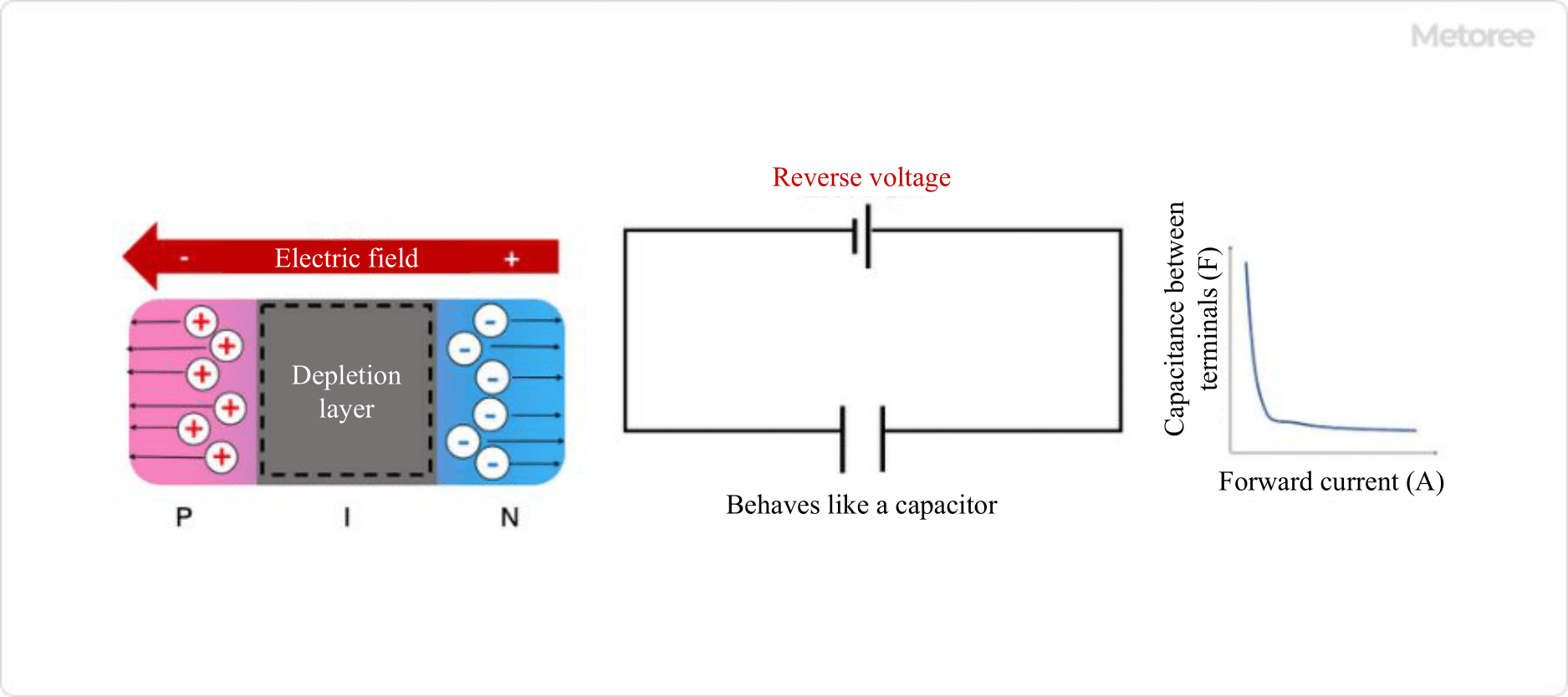
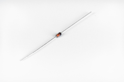
A PIN Diode is a diode with a true I-type semiconductor of high electrical resistance between the P-type and N-type semiconductors and a wide depletion layer.

The wider depletion layer improves the response characteristics. The forward voltage is almost the same as that of a PN junction diode, and PIN Diodes are used as variable resistors, especially at high frequencies, because their resistance changes with the flowing current. They can also be used as capacitors when reverse voltage is applied.

Uses of PIN Diodes

PIN Diodes have low capacitance between terminals, low series resistance, and high frequency characteristics. Therefore, they are used for switching high-frequency signals such as those used in cellular phones, since they do not easily affect high-frequency communication lines. It is also used in band switching, AGC circuits, and receiving attenuators as a variable resistor because of its ability to change resistance in response to current. It also acts as a capacitor when a reverse voltage is applied.

Principle of PIN Diode

1. When a Forward Voltage Is Applied to a Pin Diode

94_PIN-Diodes_PINダイオード-1.png

Figure 1. Forward voltage applied to the PIN diode

When a forward voltage is applied to a PIN Diode, holes from the P-type semiconductor and electrons from the N-type semiconductor move into the I-type semiconductor, where they meet and recombine. The holes and electrons from the P-type and N-type semiconductors meet in the I-type semiconductor, resulting in a change in resistance. In other words, the resistance changes in response to voltage, making it possible to use the device as a variable resistance by controlling the voltage.

In addition, by changing the thickness and area of the depletion layer of the I-type semiconductor, the capacitance between terminals can be varied and the resistance characteristics can be selected Compared to PN-type semiconductors that do not have an I-type semiconductor, PIN Diodes have improved performance because they are more effective in accumulating carriers such as holes and electrons.

2. When a Reverse Voltage Is Applied to a Pin Diode

94_PIN-Diodes_PINダイオード-2.png

Figure 2. Reverse voltage applied to PIN diode

On the other hand, when a reverse voltage is applied, holes and electrons gather on the P-type and N-type surfaces respectively, and the I-type semiconductor becomes a dielectric and acts as a capacitor.

Other Information on PIN Diodes

1. Conductivity Modulation of Pin Diode

Conductivity modulation refers to the change in resistance due to the flow of carriers into the high-resistance layer when biased.

The I layer, sandwiched between the P and N layers, consists of elements with tetravalent valence, such as silicon (Si) and germanium (Ge). These are called true semiconductors because they are pure semiconductors containing no other elements. They are insulating layers in which electrons cannot move because they are bound by stable covalent bonds with eight electrons.

However, when forward biased in a PIN Diode, holes flow from the P layer and electrons flow from the N layer, and the I layer becomes highly doped. As a result, conductivity modulation occurs and the I layer, which had high resistance, becomes low on-resistance as current flows in the forward direction.

2. Switches with PIN Diodes

PIN Diodes are also used in high-frequency switches. While mechanical switches are also available in the low-frequency range, coaxial relays and semiconductor switches are used in the high-frequency range. In recent years, they are also used as millimeter-wave band MMIC switches due to the spread of LAN communication systems and in-vehicle radar systems.

The principle of PIN Diode switch circuits is that high-frequency signals are output during forward bias and no high-frequency signals are output during reverse bias. Both reflective and absorptive types exist in the product lineup. Reflective switches transmit high-frequency power during reverse bias and reflect it during forward bias. Absorptive switches have a low voltage standing wave ratio (VSWR) and low signal loss in both ON and OFF modes.

3. Advantages and Disadvantages of PIN Diode Switches

In general, PIN Diode switches are superior in terms of switching speed and small size, but they have the disadvantage of high power consumption.

The reason for the large power consumption is the need to apply a high bias to minimize insertion loss. To compensate for this disadvantage, an optical switch called MEMS (Micro Electro Mechanical System) has been developed for the millimeter wave band and is gaining market share in today’s market.

カテゴリー
category_usa

DC Solenoid

What Is a DC Solenoid?

A DC Solenoid is an electrical component that converts the electrical energy of electromagnetic force applied to a coil into mechanical energy for linear drive by a moving iron core.

Its function as an actuator is realized by a component that combines a coil with a movable iron core. A typical solenoid is based on a pull-type motion to retract the movable iron core.

By combining various movable iron core tip shapes and driving parts, movements such as “pull, push, stop, strike, and bend” can be achieved at low cost. Therefore, DC solenoids are used not only in industrial machinery applications such as home appliances, ATMs, vending machines, ticket checkers, and automatic doors, but also in various applications in our daily lives.

Applications of DC Solenoid

DC Solenoid is used in a wide variety of applications for machines and devices around our daily life because of its controllability and responsiveness, as well as its movable iron core and tip shape, which enable various movements such as pulling, pushing, stopping, hitting, and bending at low cost.

Major applications include coin sorting machines in vending machines, automatic doors and ticket gates on train platforms, locking mechanisms in parking lots and automatic doors, control devices in ATMs, and delivery boxes installed in condominiums and convenience stores.

Principle of DC Solenoid

The principle of DC Solenoid is based on Faraday’s law of electromagnetic induction. The electrical energy of electromagnetic force flowing through a coil is converted into mechanical energy for linear drive by a movable iron core.

Compared to AC solenoids, DC solenoids do not generate inrush current when energized and are quieter than AC solenoids. Normally, a DC solenoid consists of the following components: a main frame, a coil, a spring, a fixed iron core, and a movable iron core.

When current flows through the coil, a magnetic field is generated at the same time, and the movable iron core is attracted to the fixed iron core by electromagnetic induction, enabling pull-type operation. While the coil is energized, the movable iron core is attracted to the fixed iron core, and when the coil is de-energized, the movable iron core returns due to spring force.

On the other hand, there is a push type that has a push bar on the fixed iron core to push out the push bar as soon as the movable iron core is attracted to the fixed iron core. By changing these tip shapes, various operations can be realized at low cost.

Other Information on DC Solenoid

1. Difference Between AC Solenoid and DC Solenoid

AC solenoids feature higher starting current and pull force than DC solenoids. However, if an AC solenoid is overloaded and locked during movement, a large current will continue to flow, resulting in coil burnout. Therefore, when adopting AC solenoids, it is important to design them with safety considerations such as thermal fuses and overcurrent protection.

On the other hand, DC Solenoid has a small current and low pull force, so even if a moving part is overloaded or locked, the coil will not be burned out, Therefore, it is necessary to select the right solenoid depending on the operating conditions. 

2. Self-Holding Solenoid

A self-holding solenoid is a solenoid coil with a high-performance permanent magnet that is momentarily energized. The moving part, commonly called a plunger, is attracted and then held in place by the permanent magnet.

With its short energizing time, this linear movable type solenoid is ideal for electrical equipment aiming at ultra energy saving, and is an effective component for extending the operating life of storage batteries and lowering temperature rise, for example. There are two types of solenoids: a one-directional retention type in which the moving part attracts and holds in one direction when the coil is energized, and a two-directional retention type in which the moving part tries to move and hold in two directions by making a series connection of one directional retention type and passing electricity through each coil winding section.

Self-holding solenoids have two types of pole shapes: conical type and horizontal type for one-directional solenoids, and only conical type is standard for two-directional solenoids because the stroke is fixed. Since the magnetic pole shape is used according to the size of stroke and holding force, it is important to carefully check the specifications of each solenoid’s characteristic curve in advance.

カテゴリー
category_usa

Automotive Relay

What Is Automotive Relay?

車載用リレー

Automotive Relays are relays designed to fit the control of electrical components in automobiles.

There are many Automotive Relays for different applications. Since the electrical circuit design differs according to each automobile manufacturer, various relays are manufactured and sold according to the automobile manufacturer’s standards and according to the load.

Recently, when repairing electrical components in the event of an automobile breakdown, it has become possible to quickly repair the broken Automotive Relay in the electrical circuit by replacing the entire module at once.

Applications of Automotive Relays

Automotive Relays are used as relays for electrical circuits related to the control of automobiles. Automotive Relays come in many types, including relays used to control lamps such as headlights and taillights, and motor control relays used to operate power windows and door mirrors.

They are also indispensable in the electrical circuits of automobiles, such as relays used to control air conditioners and rear-glass heaters, and those used in circuits required for battery charging.

Features of Automotive Relays

89_Automotive-Relays_車載用リレー-1.png

Figure 1. Example of a typical relay structure

Automotive Relays generally have a simple structure consisting of an electromagnet with an enameled wire coil wound around an iron core, a movable contact, and a fixed contact.

There is no special structure as a control relay, but it is designed with weight reduction, vibration resistance, and durability in mind. The weight of an automobile affects fuel efficiency and driving performance. Although each Automotive Relay is lightweight, it is important to reduce its weight since many Automotive Relays are used in a single vehicle.

Also, unlike household electrical appliances, electrical components used in automobiles are constantly exposed to vibration from running and gasoline engines. To increase the durability of automobiles, relays with excellent vibration resistance and durability are used.

Another advantage of relays is their low operating noise. Automotive Relays used for motor control, such as power window operation, are often designed to be small and quiet. Another feature of relays is that they are designed for mass production to the specification requirements of each automobile manufacturer.

Types of Automotive Relays

There are various types of Automotive Relays depending on their mechanisms.

1. Hinged Relay

The electromagnetic force generated by an electromagnet attracts a piece of iron (movable contact) and turns the contact ON/OFF by its movement. In the relay shown in Figure 1, when the electromagnet is energized, the iron strip (movable contact) is attracted to the electromagnet, turning the a-contact ON and the b-contact OFF. When the current is removed, the restoring force of the return spring causes the iron strip to return to its original position, turning the a-contact OFF and the b-contact ON.

2. Plunger Type Relay

89_Automotive-Relays_車載用リレー-2.png

Figure 2. Example of a plunger-type relay structure

When the plunger is attracted by electromagnetic force and inserted into the coil, the electromagnetic force is also generated on the plunger side, resulting in a strong attractive force. This mechanism allows the plunger to travel a large distance, making it possible to control large relay contacts.

An example of use is the EV relay (SMR) shown below. The reed relay has a contact structure with a pair of magnetic leads. A coil is wound around a glass tube, which moves the reeds to turn the contacts on and off.

89_Automotive-Relays_車載用リレー-3.png

Figure 3. EV Relay (SMR) Usage Example

Among Automotive Relays, there is a relay for EVs. This relay is called an SMR (system main relay) and is inserted into the high-voltage circuit on the way to send the high power from the vehicle’s high-voltage battery to the drive inverter and other devices to open and close the main power source.

In the event of a vehicle collision, the SMR is controlled to disconnect the high-voltage battery to prevent secondary disasters such as electric shock, etc. Relays for EVs are required to be able to interrupt high-voltage DC in a short time and be compact and lightweight.

カテゴリー
category_usa

Shock Absorber

What Is a Shock Absorber?

Shock Absorbers
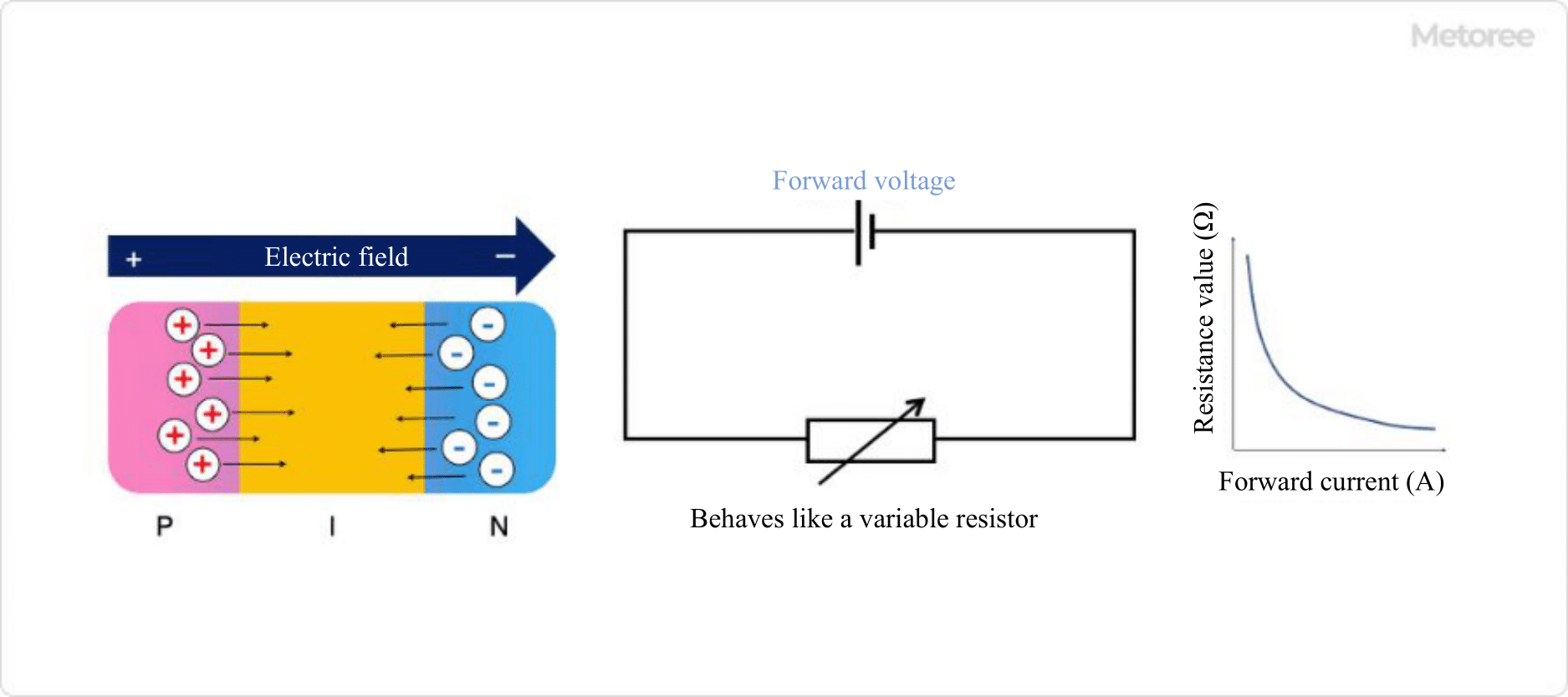
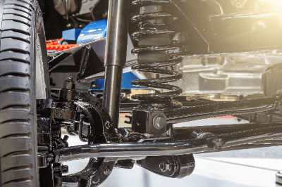
A shock absorber is a device that reduces vibrations in machinery and buildings.

In addition to suspensions, passenger cars and motorcycles use shock absorbers to reduce the impact from the ground. Springs attached to shock absorbers, absorb the shock and provide a comfortable ride.

If shock absorbers fail due to aging, it is very dangerous because their ability to absorb shock decreases, making it difficult for the brakes to work. It may also make it difficult to turn corners.

Uses of Shock Absorbers

Shock absorbers are mainly used in vehicles.

The following are examples of applications of shock absorbers:

  • Passenger vehicles such as cars and buses
  • Motorcycles, such as motorcycles and mountain bikes
  • Rail vehicles

These vehicles are equipped with shock absorbers to absorb shocks traveling on the ground. Telescopic cylinder shock absorbers are used for passenger cars, while height-adjustable shock absorbers with variable spring positions are sometimes used for motor sports vehicles with low vehicle height.

Shock absorbers called oil dampers or seismic isolation dampers are sometimes used for vibration control of houses and other structures.

Principle of Shock Absorbers

Shock absorbers can be rotary or telescopic, and telescopic shock absorbers are often used in vehicles.

In a telescopic shock absorber, the shock absorber is built inside the spring. The cylinder receives the energy of the spring, which vibrates upon impact, and absorbs the vibration by moving slowly within the hydraulic system.

At this time, the vibration energy is converted into heat energy, which causes the shock absorber to heat up. Telescopic shock absorbers can be further classified into two types: mono-tube and twin-tube.

1. Mono-Tube

Mono-tube shock absorbers are simpler in construction than twin-tube shock absorbers. A piston moves up and down inside a partially oil-filled cylinder by means of a rod that transmits the vibration of a spring. Hydraulic pressure is applied to the piston, which dampens vibration and absorbs shock.

2. Twin-Tube

The mechanism of the twin-tube is almost the same as that of the mono-tube. An additional cylinder with an oil valve is installed outside the mono-tube cylinder, making it a stronger design than the mono-tube. Twin-tube systems are installed in many passenger cars.

Regular maintenance is necessary because oil leakage due to shock absorber deterioration affects the mileage and the rate of deterioration.

How to Select Shock Absorbers

The general procedure for selecting a shock absorber is as follows:

  • Confirm the conditions of use
  • Tentatively select a shock absorber based on the conditions
  • Calculate the total energy of the collision
  • Calculate the equivalent mass
  • Evaluate the tentatively selected product

The items that must be checked when selecting a shock absorber are the maximum mass, maximum velocity, and maximum thrust of the impacted object. Care should be taken to remember to add this to the total energy, especially if thrust is generated by free fall or cylinders.

Equivalent mass is also known as the weight effect value, and each product has its own allowable range. If it exceeds the allowable range, a high reaction force will be generated at the end of the Shock Absorber’s stroke, resulting in poor shock absorption. If the equivalent mass exceeds the allowable range described in the product catalog, another Shock Absorber should be considered.

Other Information on Shock Absorbers

Shock Absorber Life Span

Shock absorber performance deteriorates with age. As the performance of a car’s shock absorber deteriorates, the tires and brake pads will wear out faster. If the car continues to be driven as it is, the shock absorber itself may break or leak oil.

The durability of a car’s suspension is generally 100,000 km or 10 years. It is also said that the recommended replacement period for shock absorber is 80,000 km. However, the lifespan depends on the roads used and the way of driving.

Highways and mountain roads place a greater load on the car and tend to deteriorate shock absorbers more easily. Unlike tires, for which there is a correlation between mileage and rpm, shock absorbers are also characterized by the fact that it is difficult to determine a definite replacement time. Therefore, it is important to determine the timing and perform regular maintenance.

カテゴリー
category_usa

Lock-in Amplifier

What Is a Lock-in Amplifier?

Lock-in Amplifiers

A lock-in amplifier is a device that has a circuit capable of extracting a component signal with a specific frequency from an input signal.

A lock-in amplifier removes noise by multiplying a reference signal and an input signal by a mixer on the device, and extracts a signal of the desired specific frequency by a low-pass filter. A device-specific value called the time constant is set, and the larger the time constant, the smaller the fluctuation of the output signal.

Uses of Lock-In Amplifiers

Lock-in amplifiers are often used in the field of optics, especially in spectroscopic measurements. They are sometimes used in combination with microscopes. Specific uses of lock-in amplifiers include astrophysical measurements such as astronomical observations, spectroscopic measurements of thin films on the order of nanometers and other experiments in which weak signals are detected.

In measurements where the sample-derived signal is weak, such as thin films less than several hundred nanometers thick, a device that amplifies the signal and eliminates noise, such as a lock-in amplifier, is indispensable. In addition, it is often used in fluorescence microscopes, Raman spectroscopy microscopes, and probe microscopes, such as atomic force microscopes.

Principle of Lock-In Amplifiers

The operating principle of lock-in amplifiers is a circuit like signal processing that detects a signal of a desired specific frequency from an input signal by amplifying the input signal with a preamplifier, multiplying it with a reference signal with a mixer, and removing excess noise components with a low-pass filter.

Within the lock-in amplifier, the input signal is multiplied by the reference signal to produce an output expressed as the sum or difference of the frequencies of the input and reference signals. If Vi=Acos(ωit+Φ) for the input signal and Vr=Bcosωrt for the reference signal, the frequency of the output is proportional to {cos[(ωi-ωr)t+Φ]+cos[(ωi+ωr)t+Φ]}.

However, since the Lock-In Amplifier acts as a low-pass filter, the only remaining component is the signal with ωi-ωr close to 0. In other words, by passing the signal through the Lock-In Amplifier, only the input signal whose frequency is close to that of the reference signal is extracted, and random components such as noise can be removed.

A sine wave is often used as the reference signal for the lock-in amplifier. A square wave is sometimes used as a reference signal to simplify the circuit and reduce cost, but in such cases, the noise rejection performance is inferior to that of a sine wave.

Other Information on Lock-In Amplifiers

1. Time Constant and Noise of Lock-In Amplifiers

A lock-in amplifier has what is called an inherent time constant. The time constant here is a value expressed as the product of the resistance of a resistor attached to the circuit and the capacitance of a capacitor. Since the magnitude of noise in the output of a lock-in amplifier is proportional to the reciprocal of the time constant, the larger the time constant, the smaller the noise in the output signal. The magnitude of a typical time constant is about 10 milliseconds to 10 seconds, while the time constant of a device that performs digital processing is about 1000 seconds.

A lock-in amplifier is affected by the signal-to-noise ratio (signal-to-noise ratio in dB), which is a measure of the noise level of the input signal. If an amplifier with a poor noise level is used in the preceding stage, the measurement accuracy of the lock-in amplifier will deteriorate, so attention should be paid to the noise level of the input signal.

2. What Is a Chopper?

A chopper is a device that rotates blades in a fixed cycle. High-sensitivity measurement combining a lock-in amplifier and a chopper is one of the most common methods in spectroscopic measurement.

By placing it on the optical path of continuous light, light is blocked when the blade is on the optical path and light is allowed to pass through when the blade is not on the optical path, thereby converting the measured light into a signal with a constant period. In measurements of crystals with large absorption coefficients or optical waveguides with large propagation loss, the measurement light is strongly absorbed by the sample, resulting in a smaller intensity of detectable light and relatively large noise effects.

In such measurements, it is more effective to use a lock-in amplifier and a chopper together. By modulating a signal with low noise and high frequency using a chopper or modulator and demodulating it efficiently using a lock-in amplifier, a signal with low noise can be obtained at the original frequency.

3. Digital Lock-In Amplifier

Today’s lock-in amplifiers are rapidly becoming digital as their frequencies are extended. A reference signal with an excellent signal-to-noise ratio and a steep low-pass filter are essential to improve the performance of a lock-in amplifier.

By utilizing a PLL (phase-locked loop) to generate a new digital sine wave internally that matches the frequency and phase of an external reference signal, distortion and extraneous noise are suppressed, and a reference signal with excellent signal-to-noise ratio is available. Steep filter characteristics can also be achieved by using a multi-stage digital low-pass filter. With the advent of this digital lock-in amplifier, high-frequency measurements up to 600 MHz can now be realized.

カテゴリー
category_usa

Detection Switches

What Is a Detection Switch?

A detection switch is a switch used to detect the position of an object and turn it on and off or switch circuits.

They operate by detecting infrared, microwave, magnetism, light, vibration, or pressure. When a switch is used to detect contact, infrared, magnetism, light, or heat, the switch is operated by the change in electrons or resistance emitted when the built-in sensing element detects light, etc. The switch is operated by the change in electrons or resistance emitted when the built-in detection element detects light, etc.

Applications of Detection Switches

Detection switches are used in stores, residences, products, production plants, and experimental equipment. When selecting a detector switch, it is necessary to consider size, detection accuracy, noise immunity, and durability.

The following are examples of detection switches in use.

  • Automatic door systems that detect the approach of a person using infrared rays and activate the system
  • Systems in factories that detect the passage of objects and sound an alarm
  • Detection systems for IC cards and magnetic strip cards at entrance gates

Principle of Detection Switches

Among detection switches, this section explains the detection methods of switches that operate by contact, switches that operate by magnetism, switches that operate by light, and switches that operate by temperature change.

  • Contact type: In the case of contact sensing, the change in pressure due to contact is measured by the amount of change in resistance of the sensing element using a diaphragm or the like, and the switch is operated. Other methods include mechanical contact actuation by contact.
  • Magnetic type: Detects the amount of change in magnetism using a sensing element such as a reed switch, Hall element, or magnetoresistive element to drive the switch. Depending on the type of sensing element used, there are switches that do not require a power supply, switches that can respond quickly, and switches with high sensitivity.
  • Optical type: Switches are operated by detecting light using a sensing element called a photodiode. A photodiode is a sensing element that converts light into electricity.
  • Thermal type: A thermal resistive element, whose resistance changes with temperature, is used as a sensing element to operate the switch. A diaphragm or the like is used to detect the amount of resistance changed by temperature.

Types of Detection Switches

There are two types of detection switches: “contact type” and “non-contact type” as the first type of detection method.

1. contact-type detection switch

Contact-type detection switches are a method that switches the contact points by the action of a physical force. Since the sensing body directly contacts the switch to switch the circuit, there is no error in detection, but there is a disadvantage that the physical contact causes the detection switch to malfunction and deteriorate over time.

2. non-contact detection switches

Non-contact detection switches are detection switches activated by magnetism or light. Unlike contact-type switches, there is no direct contact with the sensing element, so the main body of the sensing switch has a long service life. However, they tend to be more expensive than simple contact-type detection switches.

カテゴリー
category_usa

Spindle Motors

What Is a Spindle Motor?

Spindle Motors
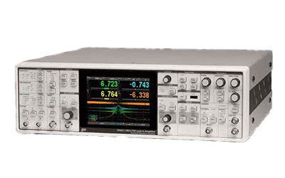
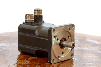
A spindle motor is a motor in which the motor part of the power source and the rotating part are integrated.

Since there is only one rotating shaft, the equipment configuration is simplified. A spindle is the rotating shaft of a rotating machine.

It is also called a spindle unit, a term used for machine tools such as lathes. Therefore, a spindle motor refers to a motor integrated with a spindle.

A typical rotation control device consisting of a motor, gears, and belts tends to be complicated to control due to the large number of parts. Spindle motors, however, make it easy to add multiple rotating shafts in parallel in a space-saving manner.

Uses of Spindle Motors

Spindle motors are widely used inside processing machines. The following are examples of spindle motor applications.

A wide range of product lineup exists, from high-torque types to products capable of high-speed rotation. It is possible to select the optimum product from a variety of spindle motors according to the application.

In recent years, spindle motors have also been used in articulated robots, where the axis of rotation of the robot arm is matched with the axis of the spindle motor. Taking advantage of their space-saving characteristics, spindle motors can also be used to drive HDD rotation.

Principle of Spindle Motors

The structure of spindle motors is often very similar to the widely used servo motors. The spindle is installed coaxially with the axis of rotation. There are two types of motors used: synchronous motors and induction motors.

1. Synchronous Motor

Synchronous motors consist of a rotor made of permanent magnets fixed to a rotating shaft and multiple circular stator units installed around the periphery of the rotor. The stator consists of electric wires wound around an iron core, and when an alternating current flows through it, it acts as an electromagnet and temporarily restrains itself.

Because the phase of the AC current changes from moment to moment, the polarity of the electromagnets also changes with time. Since the polarity of the rotor’s permanent magnet is fixed, it can rotate the rotor by alternating attraction and repulsion with the stator.

2. Induction Motor

Induction motors are motors that use a conductor rotor instead of the permanent magnet rotor of synchronous motors. A cage-shaped metal part is often used for the conductor rotor.

The principle is that a rotating magnetic field generated by the stator generates an electric current in the rotor conductor, causing electromagnetic induction action that rotates the shaft. Unlike synchronous motors, this type of motor is not suitable for fine positioning because of an error called “slippage” in the rotation phase. However, they are widely used for high output products because of their low cost and small number of parts.

Other Information on Spindle Motors

Differences Between Spindle Motors and Servo Motors

Spindle refers to the rotary shaft of industrial rotating equipment used for cutting and grinding. Therefore, the main purpose of spindle motors is cutting and grinding. Motors with ultra-high speed rotation and high torque are often used.

In contrast, servo motors are widely used in precision machinery that requires strict positioning accuracy. Assembly robots and automatic packaging equipment are examples. Driving devices such as encoders are used in motors to detect the rotational position and speed of the rotor.

This detection information is communicated with a PLC or driver to implement feedback control, enabling high-speed rotation to be controlled with high precision. Both spindle motors and servo motors of all types can be applied.

However, induction motors are often used for spindle motors and large-capacity servo motors, while synchronous motors are often used for small-capacity servo motors.