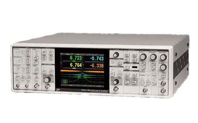
What Is a Lock-in Amplifier?
A lock-in amplifier is a device that has a circuit capable of extracting a component signal with a specific frequency from an input signal.
A lock-in amplifier removes noise by multiplying a reference signal and an input signal by a mixer on the device, and extracts a signal of the desired specific frequency by a low-pass filter. A device-specific value called the time constant is set, and the larger the time constant, the smaller the fluctuation of the output signal.
Uses of Lock-In Amplifiers
Lock-in amplifiers are often used in the field of optics, especially in spectroscopic measurements. They are sometimes used in combination with microscopes. Specific uses of lock-in amplifiers include astrophysical measurements such as astronomical observations, spectroscopic measurements of thin films on the order of nanometers and other experiments in which weak signals are detected.
In measurements where the sample-derived signal is weak, such as thin films less than several hundred nanometers thick, a device that amplifies the signal and eliminates noise, such as a lock-in amplifier, is indispensable. In addition, it is often used in fluorescence microscopes, Raman spectroscopy microscopes, and probe microscopes, such as atomic force microscopes.
Principle of Lock-In Amplifiers
The operating principle of lock-in amplifiers is a circuit like signal processing that detects a signal of a desired specific frequency from an input signal by amplifying the input signal with a preamplifier, multiplying it with a reference signal with a mixer, and removing excess noise components with a low-pass filter.
Within the lock-in amplifier, the input signal is multiplied by the reference signal to produce an output expressed as the sum or difference of the frequencies of the input and reference signals. If Vi=Acos(ωit+Φ) for the input signal and Vr=Bcosωrt for the reference signal, the frequency of the output is proportional to {cos[(ωi-ωr)t+Φ]+cos[(ωi+ωr)t+Φ]}.
However, since the Lock-In Amplifier acts as a low-pass filter, the only remaining component is the signal with ωi-ωr close to 0. In other words, by passing the signal through the Lock-In Amplifier, only the input signal whose frequency is close to that of the reference signal is extracted, and random components such as noise can be removed.
A sine wave is often used as the reference signal for the lock-in amplifier. A square wave is sometimes used as a reference signal to simplify the circuit and reduce cost, but in such cases, the noise rejection performance is inferior to that of a sine wave.
Other Information on Lock-In Amplifiers
1. Time Constant and Noise of Lock-In Amplifiers
A lock-in amplifier has what is called an inherent time constant. The time constant here is a value expressed as the product of the resistance of a resistor attached to the circuit and the capacitance of a capacitor. Since the magnitude of noise in the output of a lock-in amplifier is proportional to the reciprocal of the time constant, the larger the time constant, the smaller the noise in the output signal. The magnitude of a typical time constant is about 10 milliseconds to 10 seconds, while the time constant of a device that performs digital processing is about 1000 seconds.
A lock-in amplifier is affected by the signal-to-noise ratio (signal-to-noise ratio in dB), which is a measure of the noise level of the input signal. If an amplifier with a poor noise level is used in the preceding stage, the measurement accuracy of the lock-in amplifier will deteriorate, so attention should be paid to the noise level of the input signal.
2. What Is a Chopper?
A chopper is a device that rotates blades in a fixed cycle. High-sensitivity measurement combining a lock-in amplifier and a chopper is one of the most common methods in spectroscopic measurement.
By placing it on the optical path of continuous light, light is blocked when the blade is on the optical path and light is allowed to pass through when the blade is not on the optical path, thereby converting the measured light into a signal with a constant period. In measurements of crystals with large absorption coefficients or optical waveguides with large propagation loss, the measurement light is strongly absorbed by the sample, resulting in a smaller intensity of detectable light and relatively large noise effects.
In such measurements, it is more effective to use a lock-in amplifier and a chopper together. By modulating a signal with low noise and high frequency using a chopper or modulator and demodulating it efficiently using a lock-in amplifier, a signal with low noise can be obtained at the original frequency.
3. Digital Lock-In Amplifier
Today’s lock-in amplifiers are rapidly becoming digital as their frequencies are extended. A reference signal with an excellent signal-to-noise ratio and a steep low-pass filter are essential to improve the performance of a lock-in amplifier.
By utilizing a PLL (phase-locked loop) to generate a new digital sine wave internally that matches the frequency and phase of an external reference signal, distortion and extraneous noise are suppressed, and a reference signal with excellent signal-to-noise ratio is available. Steep filter characteristics can also be achieved by using a multi-stage digital low-pass filter. With the advent of this digital lock-in amplifier, high-frequency measurements up to 600 MHz can now be realized.