カテゴリー
category_usa

Audio Transformer

What Is an Audio Transformer?

Audio Transformers

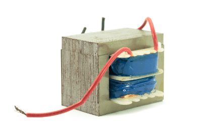
Audio transformers are transformers used to amplify sound in audio equipment.

They are generally part of the output module of an amplifier and perform the necessary conversion and filtering of the amplifier’s output signal before sending it to the speakers. Many products are available that minimize the effects of noise and other electromagnetic fields.

For this reason, they are often used to transmit micro-analog signals over long distances, such as microphone signals.

Uses of Audio Transformers

Audio transformers are used to enhance audio equipment. They are used at the input of amplifier equipment and are sometimes used to amplify audio signals. Especially in single-ended amplifiers and push-pull amplifiers, the choice of audio transformer has a significant impact on sound quality.

Selecting the appropriate transformer can improve the clarity and balance of the sound. They are also used to send the amplifier’s output signal to the speakers.

Audio transformers are placed between the power supply, output stage circuitry, and the speaker, and perform conversion and filtering of the output signal. They improve the efficiency and accuracy of the speaker and make the sound texture more realistic.

Audio transformers are sometimes used in amplifier circuits for filtering and impedance matching. They also contribute to signal stability and sound quality, especially in buffer amplifiers and microphone amplifiers.

Principle of Audio Transformers

A transformer is a device for transmitting electric power through a magnetic circuit, and power is transmitted through the magnetic coupling of two coils. Audio transformers are used to transmit audio signals. 

In audio transformers, the audio signal is input to the input coil and the transformed signal is output from the output coil. As the audio signal passes through the input coil, it generates a magnetic flux in the coil. When this magnetic flux reaches the output coil, it is converted back into an electrical signal.

In audio transformers, the magnetic properties of the components play an important role. In particular, the quality of the transformer core material and windings affects the sound quality. Additionally, transformer windings can achieve higher-quality audio signal conversion by properly designing their inductance and capacitance.

Types of Audio Transformers

There are various types of audio transformers, each of which is used for different applications depending on its characteristics. The following are examples of typical audio transformers:

1. Output Transformer

Output transformers are used in the output stage of amplifiers to send high-voltage or high-current signals to speakers. Most transformers are large and have high output power.

2. Input Transformer

These are used in the input stage of an amplifier to amplify low-level signals. They are often made of high-quality materials to ensure clear transmission of audio signals.

3. Matching Transformer

Connected between the input and output transformers, matching transformers provide proper impedance matching. They are used to improve signal transmission quality and reduce noise and distortion.

4. AC Power Transformer

AC power transformers are used to supply power to amplifiers. They are installed to remove noise and other interference from the AC power supply, improving the quality of the power supplied to the amplifier.

5. Plug-in Transformer

Plug-in transformers are used for wiring audio transformers. They are typically small and inexpensive and are used in a wide range of applications.

How to Select an Audio Transformer

When selecting an audio transformer, consider the application, impedance, quality, and size.

First, the type of audio transformer is selected based on the application. When selecting an output or input transformer, the transformer impedance must match the impedance of the amplifier’s output and input stages.

In addition, careful attention should be paid to the quality of the selection. Selecting a product that uses high-quality materials and technology will improve sound quality.

Size and shape are also influential factors. If a smaller size is required or a special shape is needed, an appropriate transformer should be selected.

Wiring Protectors

What Is a Wiring Protector?

wiring protection

Wiring protectors are products that protect various types of wiring from force and electrical action.

There is a wide range of products, many of which are tube-shaped, with snap-button closures or slits.

Among them, corrugated tubes are often used because they are strong, soft, easily bendable, and easy to remove.

Each tube is available not only for indoor use, but also for heat-resistant or cold-resistant outdoor use, depending on the material.

Uses of Wiring Protective Materials

Shape-memory braided tubing is lightweight and flexible, so it can be used as a wiring protector to flexibly bundle wires, and is used to bundle airplane wiring, concerts, and theater sound and lighting equipment.

In addition, corrugated tubing in the form of bellows with slits is widely used in automobiles, construction machinery, agricultural machinery, home appliances, and housing, especially for protecting wiring harnesses.

Grommets are used to protect wiring from damage caused by holes in panels such as wiring pullouts.

Principle of Wiring Protective Materials

Each wiring protector basically protects the wiring by covering it with a tube or similar material. Protective materials with slits are more easily inserted into the wiring. The part number is selected by comparing the inner diameter of the wire that fits the protective material with the natural inner diameter of the tube. In addition, the use of the tube will vary depending on the material of the tube. Descriptions of materials are provided below.

1. Polypropylene

Insulating and does not conduct electricity. It is often used for standard tubing because of its flexibility and resistance to cracking. It is also inexpensive and available in a wide range of sizes and colors.

2. Nylon

This material can withstand temperatures as high as 100°C and is insulating. It tends to be slightly harder and more expensive than polypropylene. It has excellent weather resistance and is preferred for outdoor use.

3. Nylon (containing rodent repellent)

This product can reduce damage caused by rodent bites when used indoors or outdoors. It is designed to cause irritation and pungency when gnawed by rats, preventing wire breakage.

4.Chlorotrifluoroethylene

It is elastic, slippery, and heat resistant up to about 150℃. It is however, expensive.

Other products with self-extinguishing properties and heat resistance up to about 180°C, such as silicon braided and glass braided tubes, are also available.

Impedance Analyzers

What Is an Impedance Analyzer?

An impedance analyzer is an analyzer of impedance (resistance).

Impedance is the ratio of voltage to current in an AC circuit and is an indicator of the resistance to current flow. Impedance is expressed as a vector quantity in the complex plane, with reactance on the imaginary axis and resistance on the real axis.

When the current is direct current, there is only a resistance component, expressed as V=IR, which is represented by Ohm’s law. There are two main types of resistance in reactance, inductive reactance for the L (inductor) component representing a coil or other winding, and capacitive reactance for the C (capacitor) component representing a capacitor. The impedance analyzer is a machine that analyzes the impedance, which is the electrical resistance including the AC component.

Uses of Impedance Analyzers

Impedance analyzers are used to analyze the details of impedance, which is electrical resistance that includes an AC component.

For example, most impedance analyzers display a graph of the analysis results on the screen of the impedance analyzer, with the horizontal axis representing frequency and the vertical axis representing the parameters (variables) that the user wants, such as voltage and current. A similar device called an LCR meter is also available.

However, an LCR meter only displays pinpoint results numerically, while an impedance analyzer can display graphs showing various parameters over a wide range of frequency bands.

Principle of Impedance Analyzers

Impedance analyzers can measure the resistance and reactance components of impedance by applying AC signals of various frequencies and measuring current, voltage, and phase differences. There are various measurement methods such as the resonance method, I-V method, and automatic balanced bridge method.

The measurement method using the automatic balanced bridge circuit is described here as a typical example. The automatic balanced bridge circuit uses a signal source, two voltmeters, and a current-to-voltage converter. The impedance of the sample can be measured by calculating the ratio of the voltage flowing through the sample to the voltage flowing through the reference resistance.

The automatic balanced bridge method can measure a wide range of frequencies below 110 MHz. The RF I-V method is used to measure impedance at higher frequencies.

The obtained data is analyzed by plotting it graphically as a Bode diagram with frequency plotted on the horizontal axis and impedance plotted on the vertical axis, or as a Cole-Cole plot with resistance plotted on the horizontal axis and reactance plotted on the vertical axis. By analyzing these equivalent circuits, it is possible to design circuits and isolate resistance components such as electrodes.

Other Information on Impedance Analyzers

1. Difference between an Impedance Analyzer and a Network Analyzer

Impedance analyzers and network analyzers are both devices that measure the impedance components of a DUT (DUT under test) by inputting signals to the DUT and comparing the signal strength and phase that appear on the output side with the input.

Impedance analyzers are used to accurately measure high impedances of 10 kΩ or higher. However, the frequency range that can be measured is limited to about 100 MHz.

Network analyzers can measure up to about 10 GHz and are suitable for measuring impedances of 10 kΩ or lower. Devices for communication equipment require measurement of characteristics up to the high-frequency range, so network analyzers are used.

2. How to Use an Impedance Analyzer

These four terminals are used for impedance measurement:

  •  Terminal for applying input current
  • Terminal for measuring input side voltage
  • Terminal for measuring output side current
  • Terminal for measuring output side voltage

The object to be measured (DUT) is placed between the input and output sides, but for more accurate measurement, a measurement jig called a fixture is used. The fixture is an important measurement jig used to hold the DUT stable, reduce extraneous noise, and prevent attenuation of signal propagation.

カテゴリー
category_usa

Industrial Sensor

Applications of Industrial Sensors

Industrial sensors are used to measure the outer diameter of steel materials and the thickness of sheet film. Because they can scan continuously at minute intervals of 0.1 second or less, they are suitable for use in manufacturing plants where the object to be measured is long and continuous and is continuously measured without being cut off in the middle.

Also, the industrial sensor can be used orthogonally to measure dimensions in the XY direction, or two or more industrial sensors can be used to measure one end face of an object that has a large cross-sectional shape.

Principle of Industrial Sensors

The principle of an industrial sensor measures the length of an object by irradiating a laser beam onto the object to be measured and using the sensor to detect the width at the point where the laser beam is blocked. It is important that the laser beam is emitted parallel to the measurement axis.

The part where the laser beam is blocked is considered an edge, and the sensor detects the width at both of these edges to enable dimensional measurement. Therefore, the configuration must be divided into a light-emitting part that emits the laser, a light-receiving part that reads the emitted laser, and a display part that displays the measured values.

The laser can be a strip or a rectangle with a width of 1.5 mm or more. The light-receiving part that reads the laser needs to continuously read the laser and the part that does not receive the laser in one section, so CCD line sensors are used in most industrial sensors.

The scanning interval for reading edges and measuring dimensions depends on the processing speed of the display unit. However, a typical product can scan at 0.1-second intervals, enabling accurate measurement even if the object to be measured swings slightly.

Other Information on Industrial Sensors

1. The Difference Between the CCD Method and the Light Intensity Change Method for the Light Receiving Part of Industrial Sensors

Industrial sensors are generally available in two types of light receiving parts: CCD type and light intensity change type. The configurations for each type are quite different.

CCD Method
The CCD method uses a CCD imaging sensor to detect parallel bands of light projected onto the photodetector; the CCD is placed in a band on the photodetector side to receive parallel light, and only where an object blocks the light, a shadow is reflected on the CCD, making it possible to measure the length of the object from that portion.

Light Intensity Change Method
In this method, a lens is placed on the receiver side, and the light focused by the lens is detected by a light-receiving element such as a photodiode. Since the amount of light concentrated on an object decreases as the object blocks the light, the length of the object is detected based on the ratio of the amount of light concentrated on the object. 

2. Error Factors of Industrial Sensors and Examples of Countermeasures

While industrial sensors have the advantage of non-contact measurement, they are subject to external disturbances. In particular, in places where vibration occurs, such as production sites, it can cause errors beyond the original measurement accuracy of the device.

In the case of CCD photodetectors, some models have a shading correction function that enables calibration correction of the linearity of the internal photodetector. In such cases, it is important to perform the calibration correction before the actual measurement.

Displacement Sensors

What Is a Displacement Sensor?

Displacement SensorsDisplacement sensors are sensing devices that measure the thickness and height of the object itself.

Contact-type sensors that measure by making contact with a probe and non-contact sensors that use lasers are available.

Uses of Displacement Sensors

Displacement sensors are widely used in industry. Displacement sensors are used to measure distances, especially in processing and conveying equipment, where the position and shape of the workpiece must be detected.

They are also useful in situations where thickness information of the object to be measured is required, such as in product appearance inspections. Although thickness can be measured with calipers, non-contact displacement sensors are used for products with complex shapes or products that are defective when touched.

Principle of Displacement Sensor

When measuring the distance to a certain object to be measured, either a diffuse-reflection or a normal-reflection laser displacement sensor is used. In either case, light from the laser light source is reflected off the surface of the object to be measured, and the distance is determined by detecting the reflected light at the photosensitive area.

The photosensitive area has a certain area width, and the photosensitive area varies depending on the angle of the reflected light. When the photosensitive area changes, a corresponding electric current is detected, and the distance is converted to a distance value based on this information.

Due to its structure, if the surface of the object to be measured is at an acute angle, the reflected light does not return to the photosensitive area and cannot be detected. This allowable tilt depends on the design of the displacement sensor, and in general, displacement sensors with the diffuse reflection method have a wider detection angle.

Types of Displacement Sensors

Displacement sensors are available in a wide range of products for different applications. The following are examples of displacement sensors.

1. Differential Transformer Displacement Sensor

The most typical sensor for detecting linear displacement by electromagnetism consists of a primary coil, two secondary coils, and an iron core between the coils; the primary coil acts as an exciter, the secondary coil as a detector, and the iron core is movable.

When high-frequency alternating current flows through the primary coil, electromagnetic induction induces a voltage in the secondary coil, causing the iron core to move. The moving iron core generates a voltage difference from a state of zero differential output, and this is the mechanism by which displacement can be measured.

The structural feature of this system is that the measured value rarely jumps. On the other hand, since it uses the magnetic field of the coil, the magnetic field characteristics may not be stable depending on the position of the iron core in the coil.

2. Linear Scale

Linear scales, also called linear encoders, are sensors used to measure positions and distances in a straight line with high accuracy. Two types of linear scales exist: inductosyn and magnescale.

Inductosyn consists of a fixed comb-shaped coil scale and a movable comb-shaped coil slider. When an alternating current is applied to the coil, a voltage is induced in the coil of the slider, and the displacement is measured from the change in phase.

Magnescale consists of a scale using magnetic tape or other magnetic recording media and a detection sensor. The position is detected by the movement of the detection sensor, and displacement is measured. 

3. Synchronization

Synchro is a rotary angle displacement sensor that consists of two rotating shafts: a transmitter and a receiver. When an alternating current flows through the primary coil wound around the shaft on the transmitter side, electromagnetic induction induces a voltage in the secondary coil on the receiver side.

At this time, the shaft of the receiver rotates by the same angle as the shaft of the transmitter, and the rotational angular displacement is measured.

4. Resolver

Resolvers are sensors that detect the angle of rotation by electromagnetic induction. It consists of a coil for excitation, two coils for detection, and an iron core. All of these coils are in series.

When an AC voltage is applied to the excitation coil, a voltage is induced in the detection coil. Since the output voltage varies with the angle of rotation, the rotational angular displacement is measured from this output signal.

How to Select a Displacement Sensor

When selecting a displacement sensor, first check whether the application is distance detection or shape information detection. For distance detection, select a product that can measure more than the surface angle of the object to be measured from among those that match the measurement range. For thickness measurement, check the detection range.

The required measurement accuracy is then confirmed, and specifications for resolution, detection accuracy, and linearity are selected. All of these factors affect measurement accuracy, and in general, the higher the accuracy, the more expensive the product.

In addition to the measurement accuracy, the installation space is also checked. If the installation space is small, a smaller sensor is recommended.

Circuit Protector

What Is a Circuit Protector?

Circuit Protectors
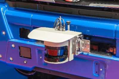
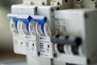
A circuit protector is a power disconnect device for instrumentation. The word “circuit” refers to an electric circuit. Therefore, the literal translation of circuit protector is “electric circuit protector,” and it is used for this purpose.

Instead of being low capacity, circuit breakers are characterized by a faster disconnection speed than general low-voltage breakers. Due to this feature, they are mostly used for protection of control circuits and instrumentation circuits. They operate before low-voltage breakers installed on the primary side to protect the upper circuits.

Uses of Circuit Protectors

Circuit protectors are used in instrumentation and control circuits. Measuring equipment for industrial applications, such as differential pressure transmitters and electromagnetic flowmeters, are called instrumentation, and the circuits used to supply power to the instrumentation and receive and transmit signals are called instrumentation circuits. Instrumentation circuits are characterized by low power consumption in spite of their high importance among industrial devices.

Circuit protectors can be used to protect the upper circuits while minimizing the effects of instrumentation circuit malfunctions. Control circuits are electrical circuits that control the power and heat sources of industrial equipment.

Large industrial motors are controlled to run and stop by electromagnetic contactors, and other drive devices. Although large motors consume oversized amounts of power, the power consumption used to control the drive device tends to be small.

However, the control circuit is of high importance because any abnormality in the control circuit will cause the industrial equipment to lose control. The use of a circuit protector minimizes the effects of a control circuit error.

Principle of Circuit Protectors

Circuit protectors in general use are divided into parts such as trip coils, contact parts, casings, and handles. The trip coil is the part that breaks the circuit by opening the contacts with the magnetic force of the electromagnetic coil in the event of an overcurrent. It is used in the disconnecting mechanism of circuit protector because it has a more immediate response than the bimetal.

The contact part is a metal part that actually conducts electricity to the circuit, and when the contact part opens, the circuit is interrupted. Copper or silver alloys are used as materials. The casing is the outer frame of the circuit protector and is made of insulating resin. It insulates the contacts from the drive spring and mounting bracket.

The handle is an interface component that allows human operation. The handle and spring turn the contacts on and off to control the conductive disconnection. Most circuit protectors are equipped with a trip-free function.

The trip-free function is a function that gives priority to overcurrent trips and opens the contacts even when the handle is locked in the “on” position. This is one of the main functions of a circuit protector and improves the reliability and safety of circuit breakage.

How to Select a Circuit Protector

Circuit protectors are used in instrumentation and control circuits; they are not often used as circuit breakers for 3-phase power motors.

The first step is to check the number of phases in the circuit. Most instrumentation and control circuits are single phase, so select a 1-phase or 2-phase circuit protector.

While a 1-phase circuit protector saves space and is more economical, it does not completely interrupt the circuit. Therefore, use the phase with 0 V to ground voltage as the common phase (common wire); if both phases do not have 0 V to ground voltage, be sure to select a 2-phase or more circuit protector.

A 3-phase circuit protector is used in circuits that indicate 3-phase voltage, such as a voltage indicator. Rarely, they are also used as circuit breakers for small 3-phase motors.

Once the number of phases has been determined, check the current rating of the equipment to be connected to the secondary side; if two or more units are connected, the total value should be used as the rated current, and a circuit breaker with a capacity greater than the rated current should be selected.

If a circuit protector is selected with less than the rated current, there is a high risk of tripping during normal use. Since control and instrumentation circuits are often of high importance and frequent tripping is uneconomical, select a circuit breaker with sufficient capacity.

Other Information on Circuit Protectors

1. Manufacturers of Circuit Protectors

Circuit protectors for industrial equipment are often manufactured by Mitsubishi Electric Corporation in Japan. Ltd. is a specialized manufacturer of FM circuit breakers, which are circuit breakers for wiring.

The company also designs and manufactures related parts such as earth leakage circuit breakers, protectors for electrical equipment protection, current limiters, various power supply devices, and, in an unusual twist, garbage disposers.

Tyco Electronics Japan also manufactures Circuit Protectors, which are sold by Asahi Giken Kogyo. Eaton Electric Japan Corp. also sells circuit protectors.

It is a wholly foreign-owned company and its birthplace is Germany, where electrical control technology was born in 1899. The former company name Muller, with over 100 years of experience since its establishment, became a member of Eaton Gr in the U.S. in 2008. Eaton Electric Japan established its Japan office in 1974, and has been providing customer support in Japan for over 45 years since then.

2. Circuit Protector Pricing

Circuit protector is available at Monotaro, an online retailer, for as low as one dollar. Many circuit breakers are made by major Japanese electronics manufacturers, such as Mitsubishi Electric and Fuji Electric, and are readily available parts unless they are special products.

カテゴリー
category_usa

Force Gauge

What Is a Force Gauge?

Force Gauges

A force gauge is a device that measures the load or tension acting on an object.

There are two types of a force gauge: the analog force gauge that does not require a power supply, and the digital force gauge that can accurately read the scale. Digital type force gauges can be connected to a PC to measure while storing data.

A digital force gauge can be held in a hand and pulled or pushed against an object to be measured, or it can be mounted on a stand for a force gauge to take a measurement.

Usage of Force Gauges

Force gauges are used in a wide range of applications including industrial machinery, mixed phase containers, food, clothing, pharmaceuticals, and sporting goods industries.

They are used to assure the quality of products and to investigate the physical properties of objects to be measured.

Depending on the intended use, the rated capacity, the corresponding physical quantity, and the durability period should be considered when selecting force gauges.

Here are some examples of force gauges applications:

  • Measurement of tensile strength in clothing buttons
  • Measurement of elasticity of bread and sponge cakes
  • Measurement of the pinching force of medical tweezers

Principles of Force Gauges

The principles of operation of force gauges are explained for the three types: analog type, digital type, and when a stand is used.

1. Analog Type Force Gauges

Analog type force gauges consist of a spring for measurement and a rack for hooking to an object to be measured or a tool for pushing against it. The force acting on the object is measured by the displacement of the spring and output by the meter. Analog force gauges are characterized by the fact that it does not require a power supply.

2. Digital Force Gauges

Digital force gauges consist of a load cell for measurement and a tool to attach to the measuring object. Force is detected by measuring the change in electrical resistance of the load cell displaced by the force of the measurement target. Some digital models are characterized by the ability to save data to a PC.

3. Force Gauges When Using a Stand

By using a stand to which force gauges can be attached, accurate elasticity and stress at break can be measured. Some models of stands are capable of a reciprocating test, and fatigue strength can also be measured.

カテゴリー
category_usa

LiDAR Sensors

What Is a LiDAR Sensor?

LiDAR

A LiDAR sensor is a device that measures the distance and shape of an object by emitting a laser beam and detecting the reflected or scattered light.

LiDAR, an acronym for light detection and ranging, is often used in time-of-flight light detection and is also known as a time-of-flight (TOF) sensor. The frequency-modulated continuous wave (FMCW) method, which utilizes the Doppler effect for advanced measurements, is another application of this remote sensing technology.

Uses of LiDAR Sensors

LiDAR sensors are crucial in automotive autonomous driving technology and smartphone image detection. They detect obstacles and vehicles nearby, aiding in the development of ADAS (Advanced Driver-Assistance Systems) to improve safety and reduce costs.

Additionally, LiDAR sensors are employed in factories alongside image processing equipment and smartphone cameras for applications such as photography focus blur, virtual reality (VR), and augmented reality (AR). The inclusion of LiDAR sensors in Apple’s iPhone 12 Pro and iPhone 12 Pro Max has significantly raised their profiles.

Principle of LiDAR Sensors

The principle of a LiDAR sensor involves using a physical method to measure the distance to an object by receiving laser light, utilizing a laser as the light source and a light-receiving element. The TOF method, the most widely used, calculates distance by measuring the time it takes for laser light to return after reflecting or scattering.

There are two laser beam irradiation methods: wide-field irradiation and scanning, which involve directing laser beams in specific directions and scanning them.

1. Wide-Field Irradiation Method

The wide-field irradiation method, akin to a TOF camera, captures the entire field of view at once with a single light beam. This method is cost-effective due to its simple optical system but can be influenced by ambient light due to reduced photon density per pixel.

2. Scanning Method

The scanning method employs a mirror to direct the laser beam, with variations such as point-scan for individual pixels and line-scan for rows. The line-scan method is preferred when high spatial resolution is not essential due to its quicker measurement time.

Other Information on LiDAR Sensors

1. Differences Between TOF and FMCW Methods

The TOF and FMCW methods differ in the physical quantities used for distance measurement. The FMCW method, which measures distance using the Doppler effect of the reflected wave, promises more advanced measurements than the simpler TOF method. Despite the challenges in coherence and cost reduction for FMCW, it is the focus of active research, especially for automated driving technology.

2. LiDAR Sensor Camera

Integrating LiDAR sensors with cameras into a single unit eliminates parallax, allowing for highly accurate, distortion-free measurements and high-resolution 3D image creation. This integration is particularly beneficial for in-vehicle sensors.

3. Demand Forecast for LiDAR Sensors

With the advancement of autonomous driving technology, led by companies like Toyota, the demand for LiDAR sensors is expected to grow significantly. Market research by the Yano Research Institute Ltd. predicts the LiDAR and laser market will reach 495.9 billion yen by 2030, with Yor Development forecasting a market size of $6 billion by 2024, indicating a rising demand in developed countries.

Laser Sensors

What Is a Laser Sensor?

Laser Sensors
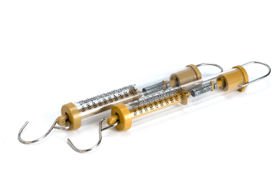
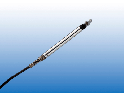
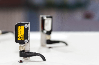
A laser sensor is a non-contact type of sensing device that uses a laser to measure the distance between the object to be measured and the sensor, as well as the thickness and height of the object itself.

Since they are commonly used sensing devices, there are a variety of measurement methods and accuracies.

User of Laser Sensors

Laser sensors can be used to measure the distance between a processing or conveying device and the object to be measured when the distance to the object needs to be accurately determined. They are also used in situations where thickness information of the object to be measured is required, such as in product appearance inspections.

Thickness measurement can be performed with contact-type calipers, but if the object has a complicated shape or is inconvenient to touch, a non-contact type laser sensor can be used for non-destructive inspection.

Principle of Laser Sensors

In principle, laser sensors allow non-contact measurement, but there are several types of methods. When measuring the distance to a certain object to be measured, either a diffuse-reflective or a normal-reflective laser sensor is used.

In both cases, light from the laser source is reflected off the surface of the object to be measured, and the distance is determined by detecting the reflected light at the photosensitive area. The photosensitive area has a certain area width, and the photosensitive area varies depending on the angle of the reflected light. When the photosensitive area changes, a corresponding electric current is detected, and this information is used to convert it into a distance value.

Due to its structure, if the light source is incident to the surface of the object to be measured that is inclined beyond a certain angle, the reflected light will not be returned to the photosensitive area and, therefore, cannot be detected. This allowable tilt depends on the design of the displacement sensor, and in general, Laser Sensors with the diffuse reflection method have a wider detection angle.

How to Select a Laser Sensor

First, check whether the application is distance detection or acquiring shape information, such as thickness and height. If it is for distance detection, select a product that can measure at or above that angle from among those that match that measurement range, assuming how much the surface of the object to be measured is inclined. For thickness measurement, check the detection range.

Then, depending on how accurate you want the measurement itself to be, select the specifications for resolution, detection accuracy, and linearity. All of these factors affect measurement accuracy, and in general, the higher the accuracy, the more expensive the product, so be careful not to over-specify.

In addition to measurement accuracy, it is also a good idea to note whether the unit itself can be installed. If there is not enough space for the mounting area, it may be necessary to select a smaller Laser Sensor.

Other Information on Laser Sensor

1. Security System With Laser Sensor

A security sensor is a system to prevent the intrusion of suspicious persons. They are utilized in all kinds of places, such as condominiums, offices, and factories, and they are designed to sound an alarm when an intruder touches the sensor. Laser Sensors are currently widely used as security sensors.

There are two types of laser sensors: horizontal detection type and vertical detection type.

Horizontal Detection Type
The laser beam is emitted horizontally at 180 °C and covers a wide area. This type of monitoring system is suitable for open areas such as outdoors and detects moving objects. The monitoring range can be set to define areas to be excluded in advance.

Vertical Detection Type
This is a security sensor in which a laser beam is emitted vertically, covering a surface perpendicular to a wall or ceiling. This type of monitoring system is suitable for localized areas such as a passageway or in front of a door and detects objects that pass in front of the surface on which the sensor is working. The height of the object to be detected can also be set. 

2. Disadvantages of Laser Sensor

Laser Sensors are convenient non-contact sensors that use light rays, but they may malfunction under some conditions.

Unevenness of the Surface of the Object to Be Detected
Laser sensors with a small spot may malfunction due to fluctuations in the amount of light received due to reflections caused by the unevenness of the surface of the object to be detected. If the surface of the object to be detected is uneven, use a sensor with a large spot.

Vibration
Vibration applied to the laser sensor may cause the optical axis to shift, resulting in a malfunction. Review the installation of the laser sensor and fix it with screws or auxiliary fittings, and install it as close to the object to be detected as possible to minimize the effects of optical axis misalignment.

Pulsed Light
Pulse lighting is a lighting method that repeatedly turns on and off. Since the light is turned on at a high frequency, it appears to the human eye as if the light is continuously turned on, although it is actually blinking.

Most laser sensors use pulsed light emitting lasers, which may malfunction against surrounding LEDs that pulse light as well as themselves. If there is a pulsing light nearby, it is important to install a shield between the sensor and the light receiving part or adjust the angle of the light receiving part so that the light does not hit the sensor.

Ball Screws

What Is a Ball Screw?

Ball Screws
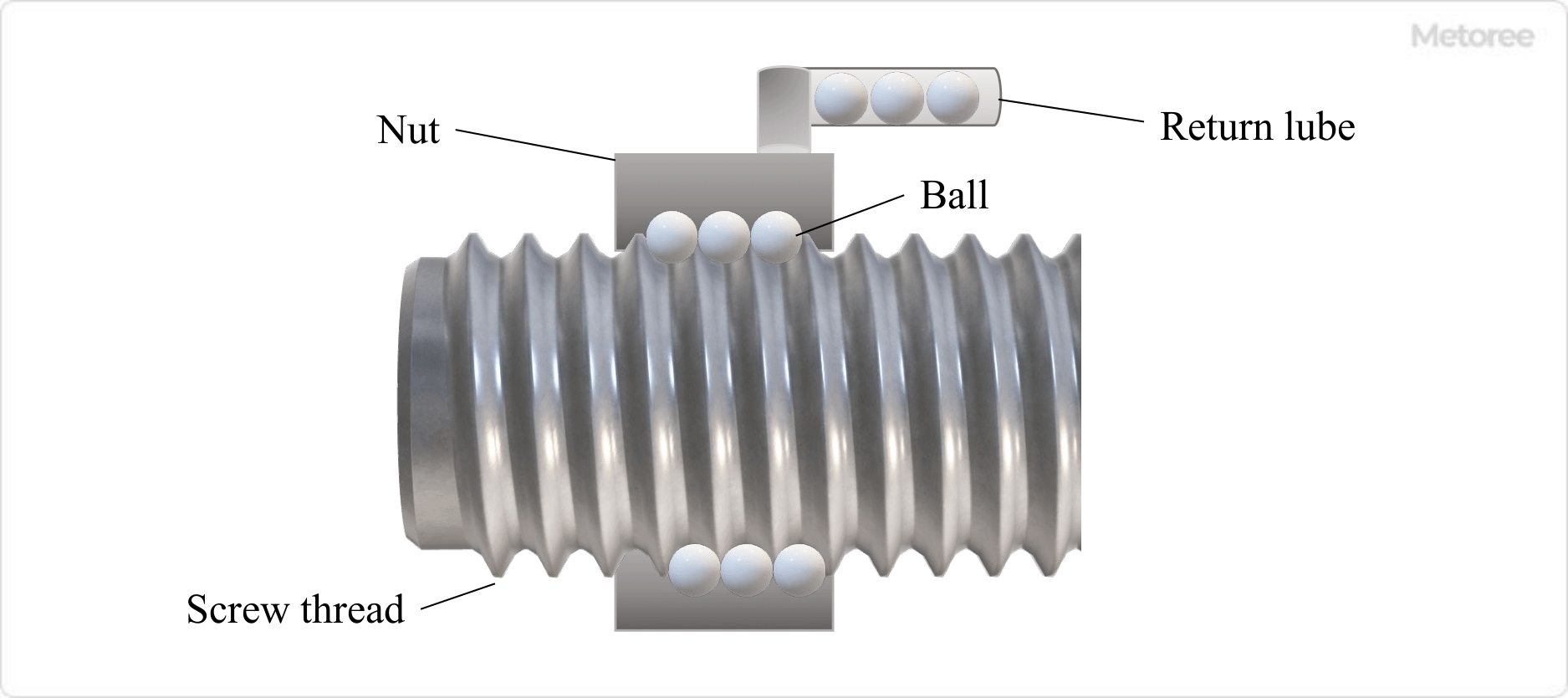
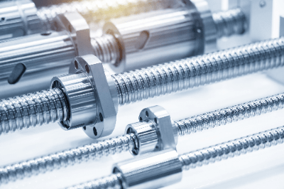
A ball screw is a type of feed screw that converts rotational motion into linear motion to move the position of a component. The screw shaft and nut are actuated by a ball. As the screw shaft and nut rotate relative to each other, the balls roll in an endless cycle. The sliding resistance between the screw and nut is much lower than that of conventional trapezoidal screws.

The precision grade of the screw and ball allows for precise motion, resulting in high positioning accuracy. They are used in automotive steering devices and precision machine tools.

Uses of Ball Screws

Ball screws are machine elements that convert the rotational motion of a motor, etc., into linear motion. Major applications include transportation and positioning of products and parts, semiconductor manufacturing equipment, industrial robots, and machine tools. Since the amount of travel (lead) per revolution of a ball screw can be precisely reproduced, high positioning accuracy can be achieved by combining it with a stepping motor.

In NC-controlled machine tools, ball screws are used to configure the feed mechanism and obtain precision positioning accuracy. Ball Screws are also used in food machinery, medical equipment, robots, injection molding machines, printing equipment, amusement equipment, automobiles, trains, aircraft, semiconductor manufacturing equipment, and inspection equipment.

Principle of Ball Screws

Ball-Screws_1

Ball screws are machine element parts consisting of a screw shaft, nut, and ball, which convert rotational motion into linear motion or linear motion into rotational motion. This component uses tribology technology that allows a ball to be placed between the screw shaft and nut and to roll lightly. It converts sliding contact motion on the screw surface into rolling contact motion. Balls need to circulate infinitely, so circulating parts are required.

There are several types of recirculation systems, such as return tube type, end deflector type, end cap type, and piece type, as well as return plate type, and their applications are classified according to size and precision. When using ball screws, a guide rail is required to guide the nut. Guide rails bear vertical loads and moment loads other than the axial load applied to the nut.

The threaded shaft is made to move with high accuracy by combining the length of the lead, which is the amount of movement per nut revolution, with the number of threaded strips. The ball is pressurized to eliminate any nut backlash, and high positioning accuracy can be obtained without uneven rotation of the screw shaft or nut.

Other Information on Ball Screws

1. Characteristics of Ball Screws

Ball screws are capable of converting the rotational motion of a machine into a linear motion. Conversely, it can also convert linear motion into rotational motion. The torque to drive the screw shaft rotation can be reduced to 1/3 or less compared to that of an ordinary screw. Therefore, the motor that drives the Ball Screw can be made smaller and lighter.

The difference between starting frictional torque and kinetic frictional torque is small, and a stick-slip phenomenon can be avoided, enabling high-precision machine control. Nuts can be preloaded by using two nuts or by using balls with a larger diameter in advance. Backlash is eliminated and rigidity is increased, resulting in better controllability.

The wear life and rolling fatigue life of ball screws can be predicted by calculation, thus increasing operational reliability. The coefficient of friction at the contact surface between the screw and nut is about 0.1 to 0.2 for a sliding screw, whereas it is 0.002 to 0.004 for a Ball Screw. Therefore, the transmission efficiency is high and over 90%.

Since dimensions and accuracy are internationally standardized and mass-produced in dedicated factories, they are easy to use and cost-effective. On the other hand, ball screws have the disadvantage of being vulnerable to impact. Since the sliding parts are in point contact, they are prone to leave dents and other marks when subjected to impact. In addition, foreign matter entering the sliding parts may cause malfunctions or failures. When used as a slide shaft of a machine tool, it is necessary to cover it with a cover, etc., to prevent chips from getting into it.

2. Manufacturing Method of Ball Screws

Ball Screws can be classified into “rolling” and “grinding” depending on the method of production.

Rolling Ball Screw
In this method, a round bar is pressed against a tool called a rolling die while rotating to form a threaded groove by plastic deformation. Compared to grinding, the accuracy grade tends to be lower.

Ground Ball Screw
This method uses a machine tool called a thread grinder to form the thread groove by grinding. Since cylindrical grinding is performed after heat treatment, the surface is smoother than that of rolling. This method is used when high-precision machine control is required, such as for slide axes of small machine tools for precision instruments.