カテゴリー
category_usa

Evaluation Board

What Is an Evaluation Board?

Evaluation Boards

An evaluation board is an electronic board that contains ICs, circuits with specific functions, and input/output terminals.

They are also called reference boards. There are CPU evaluation boards by semiconductor manufacturers and microcontroller development boards (target boards) by microcontroller manufacturers.

Usage of Evaluation Boards

Evaluation boards are used to check the performance of mounted ICs, circuit compatibility, hardware and software development, and other purposes. It is necessary to select an evaluation board equipped with ICs and electronic components suitable for the intended use.

Examples of evaluation board uses are as follows:

  • Equipment manufacturer (evaluation)
    To evaluate the performance of mounted ICs and circuits and to check compatibility.
  • Equipment manufacturer (development)
    To develop new products and software in a short time and at a low cost.
  • Educational institutions, students, and the public
    For learning about electronics, electric circuits, programming, etc.

A wide variety of evaluation boards are available from various semiconductor manufacturers. Typical evaluation targets are as follows:

  • Automotive systems.
  • Video cameras.
  • Industrial robots.
  • Terrestrial/satellite communications.
  • Mobile communication terminals.
  • Aerospace.

Our evaluation boards are used for a wide range of products, from those close to familiar home appliances to those related to robots and satellites.

Principle of Evaluation Boards

The principle of operation is that when power is supplied, the microcontroller operates according to the program written in the memory of the microcontroller. The program can be rewritten arbitrarily, and the source code of the program created on a PC is written into the memory area of the microcontroller using software called a writer.

The hardware used to support the debugging process is an emulator. The emulator is connected to the Evaluation Board.

Evaluation Board Configuration

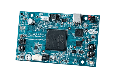
In most cases, an evaluation board consists of IC chips, communication devices, sensors, input/output terminals, etc., on a single printed circuit board. There are various types of evaluation boards depending on the components mounted on them, but microcontroller evaluation boards sold by microcontroller manufacturers are widely used in general.

Microcontroller evaluation boards are used to evaluate and experiment with the functions and circuit characteristics of the microcontrollers on which they are mounted.

1. Microcontroller

A microcontroller is an LSI that writes programs and combines circuits to perform arbitrary operations. It consists of a CPU that performs various processes and flash memory or SRAM for writing programs. 

2. Power Supply IC

An IC that generates the voltage required for a microcontroller to operate from a power supply voltage of 100 VAC. 

3. Clock

An oscillator with a specific frequency that operates the microcontroller. It is sometimes built into the microcontroller. 

4. Communication Device

A USB terminal or LAN for communication with an external PC for programming. 

5. Input/Output Terminals

USB pins for communication/power supply and input/output (I/O) pins for sending data to external interfaces.

Debugging functions include LEDs and a reset button for visual confirmation of the microcontroller status, a switch for switching operations, a sensor for measuring external information, and a 7-segment display for displaying collected data.

Other Information on the Evaluation Board

1. ICE (In-Circuit Emulator)

It can take on the functions of a CPU and can be attached to a board under development in place of a CPU to enable verification of program operation. Since there is no microcontroller on the target board, the ICE itself has an emulation chip and memory, and the target board is responsible for the operation of peripheral circuits. Advanced debugging functions such as real-time trace can be used.

Generally, a sample program for operating a microcontroller Evaluation Board is included.

2. How to Use an Evaluation Board

Evaluation boards are often used by connecting them to a PC for evaluation. The interface is typically USB, RS232C, or other terminals that the PC is equipped with.

The power supply for the board may come with an AC adapter that can be plugged into an ordinary household 100 V outlet. Or, it may be a cable that connects to a power supply unit such as a regulated power supply instead of an AC adapter.

The environment on the PC for evaluation is typically provided by the manufacturer of the evaluation board, using a software package specific to that evaluation board. However, the manufacturer or other party that receives the delivery may prepare its own software for evaluation.

In addition, since waveform measurement is frequently performed using measurement devices such as oscilloscopes and logistic analyzers, some evaluation boards may have terminals for connecting such devices in advance.

The Price of Evaluation Boards

Prices vary widely depending on the semiconductor manufacturer and the purpose of the board.

Note that when a manufacturer orders a full custom-made board for the development of its own products, the cost will depend on the quotation from the semiconductor manufacturer.

Control Relays

What Is a Control Relay?

Control Relays
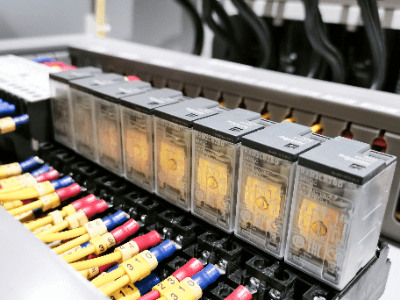
A control relay is a component that receives an electrical signal and outputs a digital signal to control a machine.

The name “control relay” is derived from the image of a baton relay, in which one input originates and affects another output.

Uses of Control Relays

Control relays are one of the most widely used components in industry and everyday life. The following are examples of control relay applications:

  • Control of automatic conveying equipment
  • Inside PLCs (Programmable Logic Controllers)
  • Inside personal computers
  • Inside home appliances such as air conditioners and automatic vacuum cleaners
  • Inside transport vehicles such as automobiles and motorcycles

Mainly used to pass input signals from sensors or push buttons to another device. Because they are used in places where control is being performed, they are used not only in industrial equipment but also in electrical appliances.

If the control system is complex, reproducing it with control relays requires several hundred points and is complicated, so PLCs and PCs are used to output calculations. However, if only a few relays are used, it is cheaper and easier to use electromagnetic relays for control.

Principle of Control Relay

There are two types of control relay, one with a contact point and the other without a contact point.

1. With-Contact Relays

Contact relays are relays that mechanically operate their contacts to output a contact signal. They are also called mechanical relays because of their operating principle. It consists of electromagnetic coils and contacts.

When the relay receives an input voltage signal, the internal electromagnetic coil is excited. The excited electromagnetic coil acts as an electromagnet and operates the movable contact, which moves together with the movable iron strip. The movable contact makes contact or pulls away from the fixed contact and outputs an electrical contact signal.

When the input voltage is removed, the contacts return to their positions by being pushed back by an internal return spring. The electromagnetic coil consists of copper wire wound around an iron core and coated with varnish for insulation.

In addition, silver alloys or gold are used on the contacts to reduce electrical resistance. They are generally protected by a casing to prevent easy human contact. 

2. Contactless Relay

A contactless relay is a component that uses a semiconductor to output a contact signal without physically operating the contact. Because of their operating principle, they are also called solid-state relays. The main component of a solid-state relay is a photocoupler.

First, when a voltage is applied to the input terminal, the LED inside the photocoupler is excited, and the LED generates light that is directed to an internal light-receiving element. The light-receiving element uses a phototransistor that conducts by light and thus outputs a contact signal by the light from the LED.

The characteristic of a contactless relay is that there is no mechanical contact, as in the case of a relay with a contact point, so there is no metal wear due to opening and closing operations. The transmission speed is also high, making it suitable for high-speed and high-frequency opening and closing. Other features include good insulation, no need for noise suppression, easy miniaturization, and no operating noise.

However, a drawback is that semiconductor elements are quickly damaged when voltages and currents exceeding their ratings are applied. They are vulnerable to heat and require adequate heat dissipation measures. They are also more expensive than contact relays.

Types of Control Relays

Control relays have the following three types of contacts:

1. A-Contact

The A-contact is a contact that is open when no signal is input to the input terminal and conducts when a signal is input. It is also called a normally open contact or a make contact. It is the most common type of contact that provides signal isolation only.

2. B-Contact

The B-contact is a contact that conducts when no signal is input to the input terminal and opens when a signal is input. It is also called a normally closed contact or a break contact.

It is characterized by the opposite action of the A-contact and can invert and output the input signal. It is often used in interlock circuits and fault interrupting circuits. 

3. C-Contact (Transfer Contact)

The C-contact is a three-terminal contact that combines an A-contact and a B-contact. It has three terminals: a common terminal, an A-contact terminal, and a B-contact terminal. When no signal is input to the input terminal, the common-b contact terminal is conducting and the common-a contact terminal is open.

When a signal is input to the input terminal, the common terminal-b contact terminal is open and the common A-contact terminal is conducting. It is used for circuits that switch between forward and reverse rotation. Another feature of the C-contact is that it is applicable only to contact relays.

カテゴリー
category_usa

DC Servomotor

What Is a DC Servo Motor?

DCサーボモーター

A DC Servomotor is a servomotor that operates on DC.

DC Servomotors are used in precision equipment, etc. Since DC Servomotors are controlled by detecting the motor’s speed and position, they are generally integrated with a motor and a sensor that detects speed and position, such as an encoder or resolver. The motor is controlled by a sensor that detects the speed and position of the motor.

To rotate a DC motor, current supplied to the motor must be passed to the rotating shaft by a component called a brush, which wears out due to wear and tear on the brush, requiring periodic maintenance.

Uses of DC Servo Motors

217_DC-Servomotors_DCサーボモーター-1.png

Figure 1. Uses of DC servo motors

DC servo motors are widely used in industrial robots that require precise control. Compared to general-purpose motors, DC servo motors respond more quickly to signals from robot controllers of industrial robots to output rotation speed and torque, and function as actuators for precise movement of robot arms and other parts.

DC servo motors are also used for the steering angle drive of radio-controlled vehicles, XYZ axis drive of machine tools, positioning drive of precision equipment, etc. It is important to select a DC servo motor appropriately according to the level of output and torque capacity, accuracy, and response speed required by the equipment to be used.

Principle of DC Servo Motor

217_DC-Servomotors_DCサーボモーター-2.png

Figure 2. Principle of DC servo motors

A DC servo motor consists of a “motor,” an “encoder,” and a “controller.” It is composed of a permanent magnet, an iron core (rotor) divided into two or more parts, coils wound around each iron core, electrodes, and brushes that pass current through the coils.

The principle of operation of a DC servo motor is explained separately for the motor and other functions.

1. Motor

The motor is made to rotate by the Lorentz force generated from two sources: the current flowing in the coil and the magnetic field from the permanent magnet, which causes the iron core to rotate. When applying current to the coils, direct current from the outside is passed through brushes to the iron core and then transmitted to the coils. Since the current is passed directly to the coil, the Lorentz force can be quickly controlled and the response speed is fast.

2. Other Functions

DC servo motors use command signals transmitted from an external controller to rotate the motor to achieve a commanded target value. The encoder attached to the motor sends speed and position information to the controller, which performs feedback control based on the position and speed information from the encoder in response to commands sent from the controller so that the motor’s rotation speed and rotation position approach the target values.

Control of DC Servo Motor

217_DC-Servomotors_DCサーボモーター-3.png

Figure 3. Control of DC servo motors

DC servo motors can be controlled in the following three ways

1. Position Control

DC servo motors are equipped with an encoder, a sensor that detects rotation angle and position and feeds back the detected rotation speed and position to the controller. If a position deviation from the command position is detected, a position correction command is issued by applying a gain to the amount of deviation to enable highly accurate control that moves the motor to the desired position and then stops the motor.

2. Speed Control

The simplest way to control the speed of a DC motor is to vary the voltage applied to the motor. In the case of a DC servo motor, a variable resistor is used to control the speed of the motor.

For DC servo motors, instead of a variable resistor, the voltage applied to the motor is controlled via an H-bridge composed of power semiconductors such as IGBTs and FETs that are incorporated in the servo amplifier.

On the other hand, the speed control of AC motors requires changing not only the voltage applied to the motor but also the drive frequency, whereas DC motors are widely used in small motors for speed control because they only change the voltage.

3. Torque Control

Torque control of the DC Servomotor is based on the proportional relationship between current and torque. Therefore, the current is controlled to maintain the torque at a constant value by detecting the current from the voltage value of the current sensor or current shunt resistor and feeding back the current command.

Other Information on DC Servomotor

Types of Servo Motors

Servomotors are constructed to be more durable than ordinary motors to operate repeatedly even in harsh environments and can be broadly classified into two types: DC Servomotors and AC Servomotors.

1. DC Servo Motor
DC Servomotor is a servomotor driven by a DC power supply. DC Servomotor is used in a wide variety of applications because it is easier to control rotation and more efficient than AC Servomotor, and its simple mechanical structure makes it inexpensive. However, the disadvantage of DC servomotors is that they have mechanical wear parts called “brushes” that require periodic replacement and maintenance.

2. AC Servo Motor
AC Servomotors are servo motors driven by an AC power source. Compared to DC motors, AC Servomotors are more complicated to control, but they are used in equipment in almost all industrial fields due to their high practicality, such as the progress in control technology and the trend toward smaller and lighter robots.

There are two types of AC motors: synchronous (SM) motors that use permanent magnets and induction (IM) motors that do not use permanent magnets, but currently synchronous motors are mainly used.

Sound Level Meters

What Are Sound Level Meters?

Sound Level Meters
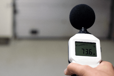
Sound level meters are devices that measure environmental noise, and noise emitted by machinery.

In measuring noise level, it is necessary to consider how people hear the sound, rather than simply measuring the volume. Therefore, the ‘noise level’ calculated by weighting the sound pressure of loud or unpleasant sound is used to measure the degree of noise.

There are two types of sound level meters, the ordinary sound level meters and the precision sound level meters, depending on the accuracy of noise measurement.

Uses of Sound Level Meters

Sound level meters are mainly used in industrial applications.

They are used to measure machine noise at construction sites and factories. The permissible limit of noise is set by law, and it is necessary to confirm that the noise standard is met during construction work or when new machinery is introduced.

In addition, when constructing a house, the noise level inside the house must be kept below the standard value. Therefore, sound level meters are used to measure the noise emitted from surrounding roads and trains before construction.

Principle of Sound Level Meters

Sound level meters consist of a microphone, amplifying amplifier, frequency weighting unit, noise level calculation unit, and display unit.

The principle of sound level meters can be divided into the following three steps:

1. Sound Acquisition at the Measurement Location

The role of the microphone is to pick up the surrounding sound and convert it into an electrical signal. The microphone uses a diaphragm to measure the frequency by the vibration period of the diaphragm and the sound pressure by the vibration width. The electrical signal generated by the microphone is then amplified by an amplifying amplifier.

Sound level meters are classified into two types according to the measurement accuracy of the microphone: Sound level meters and precision sound level meters.

2. Frequency Weighting

The frequency of the electrical signal amplified by the frequency weighting section is weighted according to the frequencies that are easy for people to hear.

3. Noise Level Calculation

The role of the noise level calculation section is to calculate the noise level using the weighted frequencies and sound pressure. The calculation is performed using the equal loudness curve.

How to Select Sound Level Meters

A wide variety of sound level meters are available in a wide price range from several thousand yen to several hundred thousand yen. When using a sound level meter, it is necessary to select one according to the application.

1. Selection of Precision Sound Level Meters

Sound level meters are selected when highly reliable data is required, such as in university research or in the evaluation and development of acoustic equipment.

2. Selection of Sound Level Meters

Sound level meters are suitable for measuring the environmental noise of factories and residences, although they are not required to be accurate enough to be submitted to public organizations.

3. Selection of Simplified Sound Level Meters

Sound level meters are the best choice if you want to check the noise level as a rough guide.

Although it is inferior to the former in terms of performance such as accuracy and frequency band, it can be purchased at a price starting from several thousand yen, and anyone can easily measure the noise level.

4. Selection of Frequency Response

When selecting sound level meters , it is necessary to consider the frequency response. There are two types of frequency response, “A-response” and “C-response.

The “A-weighted” frequency response is a weighting of frequencies according to the human auditory sensitivity. It is suitable for measuring daily life noise. Basically, all products are based on the A-weighted frequency response.

The “C characteristic” is easy to detect in any frequency band. If you want to measure motor driving noise accurately, you should select the product with C characteristic, which are less affected by frequency response.

Other Information on Sound Level Meters

How to Use Sound Level Meters

The most important thing to keep in mind when using sound level meters is the effect of reflected sound. Sound level meters should be placed as far away from walls and other objects as possible when measuring sound, because sound reflects when it strikes an object. Ideally, the distance should be at least 3.5m.

Sound level meters should be mounted on a tripod or something similar, with the microphone facing the sound source. If the sound level meters are held by the person taking the measurement, he/she should keep the sound level meters as far away from his/her body as possible to avoid picking up the reflected sound from the body.

LCR Meters

What Is an LCR Meter?

LCR Meters
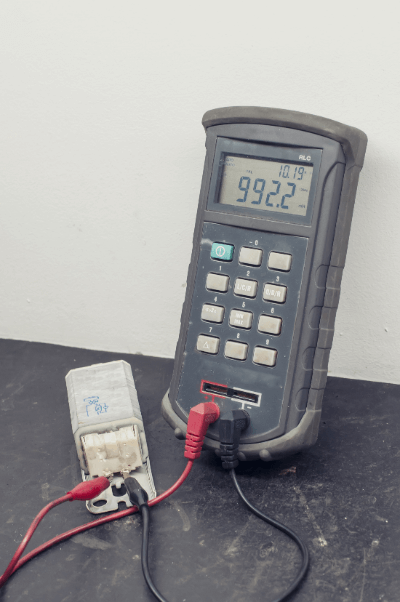
An LCR meter is a device for measuring impedance, where LCR is the symbol for L (inductance), C (capacitance), and R (resistance). Together, these three are called impedance, and an LCR Meter refers to a measuring instrument that measures impedance.

Meaning of LCR

Each component of L, C, and R has an electrical characteristic. The electrical components representing each are the coil, capacitor, and electrical resistance.

L component

The L component is called inductance. It is said that it was named L from the initial letter of Lenz’s law, which is a law concerning electromagnetic induction, but there are various theories. The unit is the Henry (H).

When the current flowing through a coil changes, it has the property of generating power in the direction that prevents the change. A circuit with a high L component will be insensitive to current changes. While it is resistant to steep noise currents, when used in AC circuits, the power factor is delayed, resulting in lower efficiency.

C Component

The C component is called capacitance. It is derived from a capacitor. The C component indicates the capacity to store electric charge, which is the source of electricity. The unit is farad (F).

A capacitor plays the opposite role of a coil in a circuit. Therefore, a circuit with a high C-component will cause a steep change in the current. In AC circuits, it advances the power factor, but there is a risk of amplifying noise currents. In DC control circuits, it plays the role of amplifying and smoothing the voltage.

R Component

The R component is called resistance. It literally means electrical resistance. The unit is ohm (Ω).

When electrical resistance is high, it is difficult for the current to flow in both AC and DC circuits. On the other hand, the maximum current at the time of a breakdown is also reduced.

Uses of LCR Meters

LCR meters are often used in the industrial field in the development and testing of electronic equipment. Specifically, they are used to test the performance of power and electronic components, such as capacitors and coils. In everyday life, LCR meters are used mainly in the medical field. A specific example is a body fat percentage measuring instrument. By measuring the impedance of the human body, body fat percentage and water content can be measured.

For the above reasons, LCR meters are also useful in medical research; they are not expensive devices like CT or NMR and have the advantage of being low cost and easy to install.

Principle of LCR Meters

Impedance measurements with an LCR meter are made by applying an alternating current to an object. The basic principle is to apply an AC voltage, measure the current and phase difference, and calculate the impedance.

The LCR meter consists of an oscillator, a vector voltmeter, and a current-to-voltage converter in a configuration called an automatic balanced bridge. This is the same configuration as an inverting amplifier circuit using an operational amplifier. The impedance calculation is done by digital conversion using an AD converter.

The most important component of the LCR meter is the vector voltmeter, which uses the lock-in amplifier principle to generate a reference signal synchronized with the input signal to detect amplitude and phase difference.

LCR meter based on an automatic balanced bridge is suitable for low-frequency measurements not exceeding 100 kHz; in the high-frequency range above 100 kHz, the effect of the impedance of the component itself, called characteristic impedance, becomes significant.

Mechanical Seals

What Is a Mechanical Seal?

Mechanical Seals
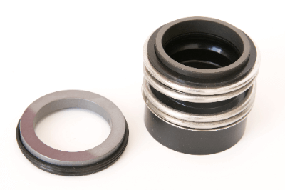
Mechanical seals reduce leakage of liquids from rotating shafts. Specifically, mechanical seals are used on the rotating shafts of machinery with rotating mechanisms, such as pumps and compressors, to prevent leakage of liquids such as water and oil from the rotating shaft.

Uses of Mechanical Seals

Mechanical seals use liquids and are widely used in industrial machinery, such as automobiles and industrial plants with rotating mechanisms, as well as in residential facilities.

Since each liquid has different characteristics, it is important to select the materials and mechanisms used in mechanical seals properly, according to the liquid. With proper selection, the mechanical seal can prevent leakage of hazardous liquids and help prevent environmental problems, while contributing to energy savings and improved equipment safety through efficient rotation.

Principle of Mechanical Seals

The basic structure of a mechanical seal consists of a rotating ring that rotates in the direction of the axis of rotation of the rotating part of the machine and a fixed ring that does not rotate. The ring-shaped “sealing” on the rotating ring is pressed against the “floating seat” on the fixed ring to slide, forming a gap between these sliding surfaces that prevents leakage of liquid.

Because of this structure and principle, some types of mechanical seal can prevent leakage of hazardous liquids under high rotation and high pressure.

Types of Mechanical Seals

There are various types of mechanical seals, and their characteristics vary depending on the sealing characteristics of the rotating ring, mounting position, and installation method. The most common types are unbalanced, balanced, rotating, stationary, inside, and outside types.

1. Unbalanced and Balanced Types

Unbalanced and balanced types are classified according to the sealing characteristics of the rotating ring. The factor that determines the pressure by the liquid is the pressure-sensitive area (A1) on the liquid side of the sealing of the rotating ring.

If the relationship between the pressure-receiving area (A1) and the sliding area (A2) is A1 > A2, the liquid pressure directly affects the sliding surface pressure. On the other hand, when A1 < A2, the pressure from the liquid is reduced.

The ratio of A1 to A2, A1/A2, is called the balance ratio (B.V.). The unbalanced type is affected strongly by the liquid pressure when B.V. > 1, while the balanced type is affected weakly by the pressure when B.V. ≤ 1.

2. Rotary Type and Stationary Type

The rotating type is a mechanism in which the sealing rotates in synchronization with the shaft, while the stationary type is a mechanism in which the sealing is fixed and does not rotate. The rotary type can be smaller than the stationary type, but the sealing is easily deformed when rotating at high speeds, which may lead to defects.

3. Inside Type and Outside Type

The inside type is a mechanism in which the leaking liquid travels from the outside to the inside, while the outside type is a mechanism in which the leaking liquid travels from the inside to the outside. The inside type is characterized by improved sealing because the liquid is affected by centrifugal force.

The outside type, on the other hand, has the advantage of being less susceptible to corrosion because it can be constructed so that the liquid has less contact with the Mechanical Seal.

Other Information on Mechanical Seals

1. Comparison of Mechanical Seal and Gland Packing

In addition to mechanical seals, gland packings are also useful in preventing liquid leakage from rotating parts of rotating machines. Therefore, we will explain the features, advantages and disadvantages of Mechanical Seal and Gland Packing.

Mechanical Seal

  • Leakage volume: Minute
  • Structure: Complex
  • Cost: Initial (at time of installation) = large/ Running = small
  • Life span: Relatively long

Gland Packing

  • Leakage: Some leakage required for use
  • Structure: Simple
  • Cost: Initial = small/ Running = large (periodic replacement is necessary, consider the time required for retightening)
  • Life span: Relatively short

Depending on the fluid used, mechanical seals and gland packings are used, but gland packings are generally used when there is no danger of leakage, such as water. On the other hand, mechanical seals are generally used when there is no danger of leakage from hazardous materials.

Gland packing is often used for equipment that uses powder in addition to fluid. However, consideration should be given when using mechanical seals for equipment that contains foreign matter in the fluid, such as wastewater, or viscous liquids, such as slurry.

If these fluids are mixed between sliding surfaces or adhered to the sliding surfaces, there is a high possibility that the sliding surfaces will be scratched and leakage will occur. In addition, if they get into and adhere to the springs that are used to press seals and mechanical seals together, the spring tracking ability may be impaired, leading to leakage in some cases.

2. Life of a Mechanical Seal

The life of a mechanical seal depends greatly on the specifications of the machine. The fluid used, machine operating hours, number of operations, and fluid temperature are the main factors that determine the service life. Basically, the approximate service life is tentatively determined based on the past installation experience and set as a cyclic replacement, but generally, the service life is 2 years.

For those that do not have a set replacement cycle, the timing for replacement depends on the importance of the equipment, but if the amount of visual leakage increases, it is time to replace the seal. Mechanical Seals provide a non-contact seal.

Therefore, they can be used maintenance-free as long as the springs that keep the sliding surfaces even and the packings that prevent fluid intrusion do not wear out. However, consumables must be replaced periodically to prevent leakage as they deteriorate over time.

カテゴリー
category_usa

Limit Switch

What Is a Limit Switch?

Limit Switches

Limit Switches are switches that are activated by the movement of machine parts or the presence of objects. As part of a control system, they are used to detect safety interlocks or objects passing through a specific position to automatically start or stop a machine, limit the range of motion of a machine, or detect its position.

Limit Switches are microswitches built into a metal or plastic case with an enclosed case to protect them from external forces, water, oil, gases, and dust in the operating environment. The contact is turned on and off by the movement of an actuator (mechanical sensing part).

Actuators include plunger type (direct-acting type), rotary lever, fork-lock lever, flexible rod, etc., and are available in a variety of shapes according to the application and operating environment.

Limit Switch Applications

Limit Switches are used to turn on or off an electric circuit based on the result of detecting the position of an object.

In automation systems for automatic control of factory production lines and the like, Limit Switches are used to detect the movement and position of machines. For example, Limit Switches are installed in the detection position and turn on at the abnormal operation position to alarm and stop the machine operation.

Another familiar example is an elevator cage (a conveyor that carries people and luggage up and down). When the cage reaches a certain position on the floor where it stops, the limit switch activates to stop the motor and the cage comes to a stop.
Limit switches are thus used in a variety of applications in automatic control systems.

Principle of Limit Switches

A basic Limit Switch consists of a body, head, microswitch, plunger, rotating shaft (rotating lever and fork lock bar only), and actuator.

The principle of Limit Switch is explained below for a rotary lever-type actuator.

1) The object to be detected moves, and toward the detection position.

2) The actuator is pushed by the object to be detected and rotates.

3) The rotary shaft fixed to the actuator rotates.

4) The cam on the rotary shaft pushes the plunger.

5) The movable contact attached to the end of the plunger moves.

6) The movable contact touches the stationary contact, and the electrical circuit is turned on.

How to Select a Limit Switch

There are many types and specifications of Limit Switches, and the following is a basic guide to selecting the right one:

1) Selection by operating environment

  • General type
    This type is for indoor or outdoor use in a general environment. The ambient temperature range is from -10 to 80°C.
  • Environment-resistant type
    This type is for use in the following special environments:
    High or low temperatures in the environment where the switch is used.
    Limit Switches are exposed to chemicals, oil, water droplets, or dust.
  • Spatter-resistant type
    Exposure to welding spatter.
  • Long life type
    Usage requires high durability.
  • Explosion-proof type
    Need to use explosion-proof type in hazardous area where it is used

2) Selection by actuator type

Select an actuator type that is suitable for the intended use. The following are typical examples, though several other types of actuators are available.

  • Plunger type (direct-acting type)
  • Rotating lever
  • Fork lock lever
  • Flexible rod

3) Selection by characteristics

  • Movement to operation (PT).
    The “movement” here indicates the angle or distance until the contact turns on or off.

For rotary levers and fork lock levers, the mounting position of the Limit Switch and the angle of the actuator must be set so that the angle at which the detected object rotates the actuator is greater than the movement (angle) to the operation.

In the case of plunger type and flexible rod type, the limit switch mounting position and actuator position must be set so that the distance that the detected object pushes the actuator is greater than the movement (distance) to the operation.

Note that the movement of the detected object must be kept within the actuator’s motion limit position (TTP).

  • Ratings
    Limit Switch ratings are specified for each model and are listed in the catalog and instruction manual. It is necessary to select a Limit Switch with a rating that is appropriate for the power supply used in the electrical circuit.

Limit Switch Failures and Countermeasures

Limit Switch failures may be caused by age-related deterioration due to mechanical life or wear, but the majority of failures are said to be caused by the way the switch is used. These include poor positioning of the dog or actuator and poor sealing.

Poor installation of Limit Switches is another cause of failure. If a switch installed to limit the range of motion of a machine is actuated multiple times, the position of the switch will gradually shift, and the switch may stop operating due to insufficient push-in. As a countermeasure, some switches come with a setting position indicator attached to the switch itself. If the switch is programmed to be pushed in to a preset position in advance, it will operate normally even if the switch is slightly out of position.

Care must also be taken in the design of the detectable object used to actuate the Limit Switch. The cut angle of the object to be detected should be 45 degrees or less; if it exceeds 45 degrees, the force applied to the lever shaft will be excessive depending on the moving speed of the object to be detected, which may cause a malfunction. If the moving speed is high, it is also effective to make the lever parallel to the cut surface of the object to be detected.

Also, if there is a steep step in the dog, a strong shock may be applied when the switch returns to the reference position. The ON/OFF switching of the switch should be designed to be as smooth as possible.

There are two types of plunger type switches: one seals the plunger part with an O-ring or rubber diaphragm and the other covers it with a rubber cap.

In the former type, the sealing rubber is not exposed to the outside, so it is resistant to hot foreign materials such as machine tool chips. However, it has a weak point that fine particles such as sand, chips, and dust can get caught in the sliding plunger surface.

The latter type has superior sealing performance because sand, chips, and other particles and dust do not become entrapped. However, hot foreign objects such as machine tool chips may melt or tear the rubber cap, making it necessary to select the right type depending on cost, application, and location.

When Limit Switches are operated, air is compressed and sucked by the piston motion of the plunger. Therefore, if the plunger is kept pushed in for a long time, the internal pressure in the Limit Switch becomes the same as atmospheric pressure, and the plunger may return slowly due to resistance from the atmospheric pressure when the plunger returns.

In addition, the accumulation of oil or dust on the plunger or on the sealing portion of the rotary shaft can also impede the operation of the Limit Switch, resulting in poor operation of the Limit Switch.

Temperature Controllers

What Is a Temperature Controller?

Temperature Controllers
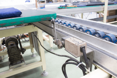
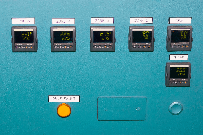
A temperature controller is a device that controls temperature by comparing the measured temperature with the set temperature.

It takes in the temperature detected by sensors such as thermocouples and thermistors, compares it with the set temperature, and outputs an electrical signal. The output signal is then used to control heaters and cooling devices to maintain the set temperature. In the home, temperature controllers are used in water heaters and air conditioners, and in industrial applications, they are often used to keep outdoor storage tanks warm.

Uses of Temperature Controllers

Temperature controllers are used to regulate and control the temperature of liquids and gases.

In industrial applications, they are often used to control process temperatures. Automatic control using temperature controllers minimizes the use of steam and electricity, contributing to energy conservation.

Also, for use in general household products, temperature regulators are used in water temperature controllers for tropical fish, water heaters, and air-cooling equipment such as air conditioners and refrigerators.

Principle of Temperature Controllers

Temperature controllers are mainly used to control heaters and cooling systems by comparing and calculating the measured and set temperatures. For a system whose temperature is to be controlled, the system generally consists of a temperature measurement sensor, temperature controller, and heating/cooling equipment.

The temperature measuring sensor measures the temperature of the object to be controlled. Resistance temperature sensors and thermistors are used. A temperature controller is an electronic device for control. It controls output by feeding back temperature. Air conditioners and heaters are used for heating and cooling equipment. Air conditioners use a compressor to compress refrigerant and can both heat and cool.

Temperature Controller Control Method

There are two types of temperature controller calculation outputs: continuous control and ON-OFF control.

1. Continuous Control

PID control is a control method that calculates input signals using proportional, integral, and derivative (abbreviation of Proportional, Integral, Derivative) elements.

In severe processes where overshoot cannot be tolerated, fine adjustments are made with differential control. Proportional control, integral control, and derivative control are abbreviated as P control, I control, and D control using the initial letters of the alphabet.

  • P Control
    Control is proportional to the deviation between the input value of the temperature measurement sensor and the temperature setpoint.
  • I control
    I control eliminates the deviation between the input value of the temperature measurement sensor and the temperature setpoint.
  • D control
    Controls used to fine-tune the difference in temperature change due to external factors. 

2. ON-OFF Control

ON-OFF control compares the measured temperature with the set temperature and turns the chiller on and off. Compared to continuous control, ON-OFF control is simpler and can be introduced at a lower cost.

Other Information on Temperature Controller

1. Thermostat and Temperature Controller

Thermostats are simple temperature controllers that have been around for a long time. It uses the expansion and contraction of a metal or liquid due to temperature to control temperature by turning contacts or valves on and off. They are often used to regulate the cooling water to radiators in automobiles and other vehicles, and to control the temperature of electric kettles. Thermostats are available in metal and liquid expansion types.

  • Metal Type Thermostats
    Metal type thermostats use a temperature sensor called a bimetal. This is a plate made of two different metals with different thermal expansion coefficients and uses the expansion and deformation caused by heat as an electrical contact point.
  • Liquid expansion thermostats
    Liquid expansion thermostats use the force of expansion and contraction of a liquid enclosed in a container as an electrical contact point. Liquid expansion thermostats are characterized by their ability to increase electrical capacity. Both types of thermostats do not require a power supply for control.

2. Temperature Controller and Heater

Temperature controllers control temperatures above ambient (room) temperature by issuing control commands to heaters (heating devices). Temperature controllers have a fixed controllable power capacity, so when a large-capacity heating device is used, a separate drive device such as an electromagnetic switch must be provided.

To control temperatures below ambient (room) temperature, a chiller or other cooling device is used. Temperature controllers, heaters, and chillers must have the appropriate specifications and capacities for the intended use. A temperature sensor is also required for temperature control. 

3. Indicating Controller and Temperature Controller

A temperature controller is a type of indicating controller. Indicating controllers control not only temperature but also humidity, flow rate, pressure, and many other factors. Both indicating controllers and temperature controllers are only arithmetic devices, and sensors and chillers are required separately.

カテゴリー
category_usa

Press Unit

What Is a Press Unit?

Press units, specifically servo presses, utilize a servo motor for numerical control to precisely manage the presser’s movement. This technology enables detailed control over the presser’s speed and frequency, offering significant improvements over traditional mechanical presses powered by hydraulic or pneumatic systems.

Uses of Press Units

Servo presses are versatile, supporting a range of applications such as press fitting, caulking, distortion correction, punching, forming, heat welding, and powder forming. They are particularly beneficial in automotive manufacturing for producing complex and lightweight components like doors and hoods.

Principle of Press Units

Servo press units employ servo motors for applying pressure, facilitating precise and complex slide movements. This system constantly monitors and adjusts its performance (e.g., speed, torque) to match predefined parameters. Unlike conventional presses, servo presses can vary their speed, allowing for nuanced operations like slow pressurization when contacting materials, thereby enhancing efficiency and accuracy. Additionally, their CNC capability enables easy integration with external systems and complex programming for advanced tasks.

Other Information on Press Units

Advantages of Press Units

Press units offer several benefits compared to mechanical presses:

  • Improved Formability: They enable the forming of materials previously challenging to press, such as high-tensile steel, stainless steel, and aluminum alloys, by optimizing slide motion to minimize wrinkles and cracks.
  • Controlled Springback: The ability to adjust press actions helps suppress springback in high-tensile steel plates.
  • Higher Precision: By constantly monitoring and adjusting the bottom dead center, servo presses maintain part accuracy despite thermal expansion or environmental temperature changes.
  • Extended Die Life: The precise control over pressing speed extends the life of dies by reducing wear.
  • Prevention of Lubricant Loss: Adding vibratory motion to the slide helps maintain lubrication effectiveness by enhancing lubricant penetration into material-die gaps.
  • Process Reduction: Complex parts requiring multiple conventional press operations can now be formed in fewer steps, reducing equipment and maintenance costs while improving precision.

Operational Amplifier

What Is an Operational Amplifier?

operational amplifier

An operational amplifier is an integrated circuit with two input terminals and one output terminal that can amplify an input electrical signal and output it.

It is also called an op amplifier. By designing the circuit elements connected to an operational amplifier, it can not only amplify but also provide arithmetic functions such as addition, subtraction, and time integration of input voltages.

Today, analog amplification circuits that take advantage of these features are widely used.

Applications of Op-Amps

A wide variety of circuits use op-amps, including:

  • Sensor amplifiers
  • Voltage follower circuits
  • Differential amplifiers
  • Additive amplification circuits
  • Integral circuits
  • Differentiation Circuit
  • Linear Detection Circuits
  • Logarithmic Amplifier Circuit
  • Phase Oscillator Circuit
  • Active Filter

1. Sensor Amplifier

Op-amps are used in the field of sensor amplifiers to amplify various small signals output from microphones, optical sensors, pressure sensors, etc., to a signal level that can be handled by an A/D converter. In order to avoid the influence of noise, differential amplifiers or bandpass filters are used to remove noise outside the frequency band of the signal.

2. Voltage Follower

Op-amps are also used as voltage followers. A high impedance signal source is vulnerable to noise and cable lengths cannot be extended. However, if an op-amp is placed near the signal source as a voltage follower, the signal can be sent out with the op-amp’s low output impedance. The use of op-amps allows for longer cables to reduce the effects of noise.

Principle of Op-Amps

Operational Amplifier consists of two input terminals and one output terminal and has the following ideal characteristics:

  • Open loop gain: infinite
  • Input current: 0A
  • Output impedance: 0Ω

In practice, the open-loop gain is more than 90 dB, the input current is several nA to 1 μA, and the output impedance is 0.1 Ω to several Ω. In principle, the above assumptions can be made.

In addition, the two input terminals of the op-amp have the following functions:

  • Inverting Input Terminal
    This is a terminal where the phase of the input signal is inverted by 180° and output, and is indicated by “-” in the circuit symbol.
  • Non-Inverting Input Terminal
    This terminal produces an output in phase with the input signal and is indicated by a “+” in the circuit symbol.

Types of Operational Amplifiers

Op-amps can be classified in terms of “elements,” “power supply configuration,” and “characteristics”.

1. Classification by Element

The following three types of op-amps are classified according to the elements that make up the circuit:

  • Operational amplifiers consisting only of bipolar transistors
    There are many types of operational amplifiers, ranging from high-performance types with excellent characteristics to general-purpose types.
  • Op-amps using FETs as input terminals
    Although basically composed of bipolar transistors, the first stage of the input circuit is a differential type source follower using J-FETs, resulting in a high input impedance and large slew rate characteristics.
  • CMOS-based op-amp
    Although the withstand voltage is relatively low, the input bias current is at an extremely low level and current consumption is low. Another advantage is the wide input/output dynamic range and the ability to handle large amplitude signals. However, it cannot handle high frequency signals.

2. Classification by Power Supply Configuration

Operational Amplifier can be classified into the following two types according to its power supply configuration:

  • Dual power supply type
    Operational Amplifier that requires both positive and negative power supply voltages relative to the ground level.
  • Single power supply type
    Operational Amplifier that operates with only positive or negative power supply voltage

3. Classification by Characteristics

Op-amps are supplied with different characteristics that are particularly important for different applications. Below are some examples of op-amps. The appropriate device must be selected based on the required specifications.

  • Wide bandwidth
  • Low noise
  • High precision
  • Rail to Rail operation
  • Low bias current
  • Low current consumption
  • High output current

How to Use Op Amps

Op amps have error factors unique to analog circuits. In addition, deviations from the ideal characteristics described in the section “Principles of Op Amps” may adversely affect circuit operation. Therefore, measures to avoid them are necessary. Specific measures are described below:

  • The power supply to the op amp should output a stable voltage with low noise.
  • Install noise-absorbing capacitors near the power supply terminals.
    Keep a distance from digital processing circuits or place the op-amp in a shielded case.
  • Install in an environment with minimal temperature fluctuation.
  • If accurate amplification and frequency characteristics are required, the design should take into account the accuracy of the feedback circuit elements and temperature characteristics.

Other precautions are listed below, but please refer to specialized literature or materials provided by op amp manufacturers for individual measures.

  • Cancellation of offset voltage
  • Preventing outgoing signals
  • Ensuring dynamic range
  • Removal of bias current effects
  • Ensuring current supply capability
  • Protection against excessive input signals

Other Information on Op Amps

Amplifier Circuit Basics

Since op-amps have extremely high open-loop gain, the various functions described in the previous section can be realized by properly setting the feedback circuit from the output terminal to the input terminal. The following two basic amplification circuits using op-amps are explained here as actual examples.

1. Inverting Amplifier
The signal Vi is connected to the inverting input terminal via a resistor Ri, and the inverting input terminal and output terminal are connected by a resistor Rf. The non-inverting input terminal is connected directly to ground. The output signal Vo obtained with this configuration is (-Rf/Ri) × Vi.” The “-” indicates that the phase is inverted. 

2. non-inverting amplifier
The signal Vi is directly connected to the non-inverting input terminal. The inverting input terminal is grounded via Ri and connected to the output terminal via Rf. The output signal Vo obtained with this configuration is (Rf/Ri) × Vi.