What Is a Limit Switch?
Limit Switches are switches that are activated by the movement of machine parts or the presence of objects. As part of a control system, they are used to detect safety interlocks or objects passing through a specific position to automatically start or stop a machine, limit the range of motion of a machine, or detect its position.
Limit Switches are microswitches built into a metal or plastic case with an enclosed case to protect them from external forces, water, oil, gases, and dust in the operating environment. The contact is turned on and off by the movement of an actuator (mechanical sensing part).
Actuators include plunger type (direct-acting type), rotary lever, fork-lock lever, flexible rod, etc., and are available in a variety of shapes according to the application and operating environment.
Limit Switch Applications
Limit Switches are used to turn on or off an electric circuit based on the result of detecting the position of an object.
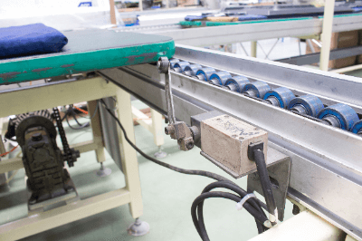
In automation systems for automatic control of factory production lines and the like, Limit Switches are used to detect the movement and position of machines. For example, Limit Switches are installed in the detection position and turn on at the abnormal operation position to alarm and stop the machine operation.
Another familiar example is an elevator cage (a conveyor that carries people and luggage up and down). When the cage reaches a certain position on the floor where it stops, the limit switch activates to stop the motor and the cage comes to a stop.
Limit switches are thus used in a variety of applications in automatic control systems.
Principle of Limit Switches
A basic Limit Switch consists of a body, head, microswitch, plunger, rotating shaft (rotating lever and fork lock bar only), and actuator.
The principle of Limit Switch is explained below for a rotary lever-type actuator.
1) The object to be detected moves, and toward the detection position.
2) The actuator is pushed by the object to be detected and rotates.
3) The rotary shaft fixed to the actuator rotates.
4) The cam on the rotary shaft pushes the plunger.
5) The movable contact attached to the end of the plunger moves.
6) The movable contact touches the stationary contact, and the electrical circuit is turned on.
How to Select a Limit Switch
There are many types and specifications of Limit Switches, and the following is a basic guide to selecting the right one:
1) Selection by operating environment
- General type
This type is for indoor or outdoor use in a general environment. The ambient temperature range is from -10 to 80°C. - Environment-resistant type
This type is for use in the following special environments:
High or low temperatures in the environment where the switch is used.
Limit Switches are exposed to chemicals, oil, water droplets, or dust. - Spatter-resistant type
Exposure to welding spatter. - Long life type
Usage requires high durability. - Explosion-proof type
Need to use explosion-proof type in hazardous area where it is used
2) Selection by actuator type
Select an actuator type that is suitable for the intended use. The following are typical examples, though several other types of actuators are available.
- Plunger type (direct-acting type)
- Rotating lever
- Fork lock lever
- Flexible rod
3) Selection by characteristics
- Movement to operation (PT).
The “movement” here indicates the angle or distance until the contact turns on or off.
For rotary levers and fork lock levers, the mounting position of the Limit Switch and the angle of the actuator must be set so that the angle at which the detected object rotates the actuator is greater than the movement (angle) to the operation.
In the case of plunger type and flexible rod type, the limit switch mounting position and actuator position must be set so that the distance that the detected object pushes the actuator is greater than the movement (distance) to the operation.
Note that the movement of the detected object must be kept within the actuator’s motion limit position (TTP).
- Ratings
Limit Switch ratings are specified for each model and are listed in the catalog and instruction manual. It is necessary to select a Limit Switch with a rating that is appropriate for the power supply used in the electrical circuit.
Limit Switch Failures and Countermeasures
Limit Switch failures may be caused by age-related deterioration due to mechanical life or wear, but the majority of failures are said to be caused by the way the switch is used. These include poor positioning of the dog or actuator and poor sealing.
Poor installation of Limit Switches is another cause of failure. If a switch installed to limit the range of motion of a machine is actuated multiple times, the position of the switch will gradually shift, and the switch may stop operating due to insufficient push-in. As a countermeasure, some switches come with a setting position indicator attached to the switch itself. If the switch is programmed to be pushed in to a preset position in advance, it will operate normally even if the switch is slightly out of position.
Care must also be taken in the design of the detectable object used to actuate the Limit Switch. The cut angle of the object to be detected should be 45 degrees or less; if it exceeds 45 degrees, the force applied to the lever shaft will be excessive depending on the moving speed of the object to be detected, which may cause a malfunction. If the moving speed is high, it is also effective to make the lever parallel to the cut surface of the object to be detected.
Also, if there is a steep step in the dog, a strong shock may be applied when the switch returns to the reference position. The ON/OFF switching of the switch should be designed to be as smooth as possible.
There are two types of plunger type switches: one seals the plunger part with an O-ring or rubber diaphragm and the other covers it with a rubber cap.
In the former type, the sealing rubber is not exposed to the outside, so it is resistant to hot foreign materials such as machine tool chips. However, it has a weak point that fine particles such as sand, chips, and dust can get caught in the sliding plunger surface.
The latter type has superior sealing performance because sand, chips, and other particles and dust do not become entrapped. However, hot foreign objects such as machine tool chips may melt or tear the rubber cap, making it necessary to select the right type depending on cost, application, and location.
When Limit Switches are operated, air is compressed and sucked by the piston motion of the plunger. Therefore, if the plunger is kept pushed in for a long time, the internal pressure in the Limit Switch becomes the same as atmospheric pressure, and the plunger may return slowly due to resistance from the atmospheric pressure when the plunger returns.
In addition, the accumulation of oil or dust on the plunger or on the sealing portion of the rotary shaft can also impede the operation of the Limit Switch, resulting in poor operation of the Limit Switch.