What Is an Operational Amplifier?
An operational amplifier is an integrated circuit with two input terminals and one output terminal that can amplify an input electrical signal and output it.
It is also called an op amplifier. By designing the circuit elements connected to an operational amplifier, it can not only amplify but also provide arithmetic functions such as addition, subtraction, and time integration of input voltages.
Today, analog amplification circuits that take advantage of these features are widely used.
Applications of Op-Amps
A wide variety of circuits use op-amps, including:
- Sensor amplifiers
- Voltage follower circuits
- Differential amplifiers
- Additive amplification circuits
- Integral circuits
- Differentiation Circuit
- Linear Detection Circuits
- Logarithmic Amplifier Circuit
- Phase Oscillator Circuit
- Active Filter
1. Sensor Amplifier
Op-amps are used in the field of sensor amplifiers to amplify various small signals output from microphones, optical sensors, pressure sensors, etc., to a signal level that can be handled by an A/D converter. In order to avoid the influence of noise, differential amplifiers or bandpass filters are used to remove noise outside the frequency band of the signal.
2. Voltage Follower
Op-amps are also used as voltage followers. A high impedance signal source is vulnerable to noise and cable lengths cannot be extended. However, if an op-amp is placed near the signal source as a voltage follower, the signal can be sent out with the op-amp’s low output impedance. The use of op-amps allows for longer cables to reduce the effects of noise.
Principle of Op-Amps
Operational Amplifier consists of two input terminals and one output terminal and has the following ideal characteristics:
- Open loop gain: infinite
- Input current: 0A
- Output impedance: 0Ω
In practice, the open-loop gain is more than 90 dB, the input current is several nA to 1 μA, and the output impedance is 0.1 Ω to several Ω. In principle, the above assumptions can be made.
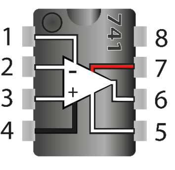
In addition, the two input terminals of the op-amp have the following functions:
- Inverting Input Terminal
This is a terminal where the phase of the input signal is inverted by 180° and output, and is indicated by “-” in the circuit symbol. - Non-Inverting Input Terminal
This terminal produces an output in phase with the input signal and is indicated by a “+” in the circuit symbol.
Types of Operational Amplifiers
Op-amps can be classified in terms of “elements,” “power supply configuration,” and “characteristics”.
1. Classification by Element
The following three types of op-amps are classified according to the elements that make up the circuit:
- Operational amplifiers consisting only of bipolar transistors
There are many types of operational amplifiers, ranging from high-performance types with excellent characteristics to general-purpose types. - Op-amps using FETs as input terminals
Although basically composed of bipolar transistors, the first stage of the input circuit is a differential type source follower using J-FETs, resulting in a high input impedance and large slew rate characteristics. - CMOS-based op-amp
Although the withstand voltage is relatively low, the input bias current is at an extremely low level and current consumption is low. Another advantage is the wide input/output dynamic range and the ability to handle large amplitude signals. However, it cannot handle high frequency signals.
2. Classification by Power Supply Configuration
Operational Amplifier can be classified into the following two types according to its power supply configuration:
- Dual power supply type
Operational Amplifier that requires both positive and negative power supply voltages relative to the ground level. - Single power supply type
Operational Amplifier that operates with only positive or negative power supply voltage
3. Classification by Characteristics
Op-amps are supplied with different characteristics that are particularly important for different applications. Below are some examples of op-amps. The appropriate device must be selected based on the required specifications.
- Wide bandwidth
- Low noise
- High precision
- Rail to Rail operation
- Low bias current
- Low current consumption
- High output current
How to Use Op Amps
Op amps have error factors unique to analog circuits. In addition, deviations from the ideal characteristics described in the section “Principles of Op Amps” may adversely affect circuit operation. Therefore, measures to avoid them are necessary. Specific measures are described below:
- The power supply to the op amp should output a stable voltage with low noise.
- Install noise-absorbing capacitors near the power supply terminals.
Keep a distance from digital processing circuits or place the op-amp in a shielded case. - Install in an environment with minimal temperature fluctuation.
- If accurate amplification and frequency characteristics are required, the design should take into account the accuracy of the feedback circuit elements and temperature characteristics.
Other precautions are listed below, but please refer to specialized literature or materials provided by op amp manufacturers for individual measures.
- Cancellation of offset voltage
- Preventing outgoing signals
- Ensuring dynamic range
- Removal of bias current effects
- Ensuring current supply capability
- Protection against excessive input signals
Other Information on Op Amps
Amplifier Circuit Basics
Since op-amps have extremely high open-loop gain, the various functions described in the previous section can be realized by properly setting the feedback circuit from the output terminal to the input terminal. The following two basic amplification circuits using op-amps are explained here as actual examples.
1. Inverting Amplifier
The signal Vi is connected to the inverting input terminal via a resistor Ri, and the inverting input terminal and output terminal are connected by a resistor Rf. The non-inverting input terminal is connected directly to ground. The output signal Vo obtained with this configuration is (-Rf/Ri) × Vi.” The “-” indicates that the phase is inverted.
2. non-inverting amplifier
The signal Vi is directly connected to the non-inverting input terminal. The inverting input terminal is grounded via Ri and connected to the output terminal via Rf. The output signal Vo obtained with this configuration is (Rf/Ri) × Vi.