カテゴリー
category_usa

Actuator

What Is an Actuator?

Actuators

An actuator is a drive device that converts various types of input energy into physical motion.

In addition to electricity, the energy input to an actuator can be pneumatic, hydraulic, electromagnetic, steam, heat, etc. By using the energy converted by an actuator, it is possible to control the movement associated with the movement of objects.

Applications of Actuators

Actuators are used in a wide variety of applications, either as devices for simple motions such as extending, bending, and turning or to generate power continuously, such as motors and engines.

Depending on the energy input, actuators are generally classified into three main categories

  • Electric Actuators: Industrial robots and transport equipment that require high-precision positioning.
  • Hydraulic Actuators: Machine tools and construction equipment that require high thrust
  • Pneumatic Actuators: General industrial and food production equipment requiring clean and simple structures

Principles of Actuators

Actuators can be broadly classified into the following principles

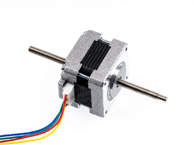
1. Electric Actuators

Electric actuators are driving devices consisting of ball screws, linear guides, servomotors, etc., and are used to transport production equipment.

Electric actuators include servomotors that use electricity as energy, electromagnetic actuators that use magnetic force from electromagnets as energy, and piezoelectric actuators that use piezoelectric elements that deform when voltage is applied.

2. Hydraulic Actuator

Hydraulic actuators use Pascal’s principle to generate fluid power, so they can provide large power even though they are small.

3. Pneumatic Actuator

Pneumatic actuators use pneumatic pressure as the power source, whereas hydraulic actuators require high loads, high pressure, and heavy equipment, so they are used as a safe method with low loads and little risk of fire.

Other Information on Actuators

1. Distinction Between Hydraulic and Electric Actuators

Actuator propulsion energy is mainly used at a power density of about 1k (W/kg), with hydraulic energy control used for higher power applications and electric energy control used for lower power applications.

Electric actuators have also been actively improving their power with technological innovations in recent years, but the power has improved significantly only in the field of brushless DC motors for small to medium actuator applications, while AC servomotors for large applications have not seen a significant increase in power since the early 2000s. AC servomotors for large-size applications have not seen a significant increase in power since the early 2000s.

Therefore, especially in the field of machine tools and construction machinery in factories that require large power densities of 10k(W/kg), hydraulic actuators are the sole domain of these applications, and electric-controlled actuators are not used in this field. However, it is also true that hydraulic energy control is desired to be electrically controlled if possible in this field from the viewpoints of running costs such as oil changes and maintenance, as well as environmental considerations.

2. Hybrid Actuator With Hydraulic and Electric Control

One of the recent technological trends is the development of hybrid actuators that combine hydraulic and electric control. Hydraulic control has generally been based on Pascal’s principle, but the problems with this type of actuator are that it requires piping equipment for oil circulation to control the flow rate of the servo valve of the working oil, which makes the equipment large, and that the working oil deteriorates due to the rise in exhaust heat temperature of the machine, which requires periodic oil changes and maintenance costs. This also caused high maintenance costs due to the deterioration of the working oil caused by the rise in the machine’s exhaust heat temperature.

The latest hybrid actuator with hydraulic and electric control enables final control of actuator output based on the drive speed of the electric servomotor rather than servo valve flow control, eliminating the need for extensive piping, and enabling highly efficient output control to suppress the rise in working oil temperature. This also reduces maintenance costs for oil changes and is suitable for environmental considerations.

カテゴリー
category_usa

Dielectric Withstand Tester

What Is a Dielectric Withstand Tester?

A dielectric withstand tester, also known as a withstand voltage tester or dielectric strength tester, is a device used to test the insulation of electric products or components against high voltages. This tester is crucial for verifying that the insulation can prevent electrical breakdown, protect users from electrocution, or prevent fire hazards.

Safety laws specify required withstand voltages for devices to mitigate such risks. Unlike insulation resistance testers, which measure insulation performance quantitatively, dielectric withstand testers qualitatively assess the presence of dielectric breakdown by applying voltages high enough to potentially cause failure.

Uses of Dielectric Withstand Testers

Dielectric withstand testers are integral to safety standards globally, ensuring that electrical products do not suffer from dielectric breakdown. They are employed alongside insulation resistance testers and protective continuity tests in the final quality assurance stages to confirm the absence of electrical shock or leakage risks.

Principle of Dielectric Withstand Testers

Dielectric withstand testers are utilized for various tests, including:

1. AC/DC Withstand Voltage Test

A high voltage is applied for a specific period to detect even minimal current leakage, confirming the product’s safety and quality. The test involves applying voltages 10 to 20 times higher than normal operational levels to identify any sudden increases in current indicating dielectric breakdown.

2. Insulation Resistance Test

Measures the DC electrical resistance by applying up to 1,000 V DC, commonly performed during maintenance and inspections outside the manufacturing process.

3. Protective Continuity Test

Tests the product’s grounding by applying a large current between the ground post and the chassis.

4. Leakage Current Test

Simulates human electrocution scenarios by measuring leakage current through a circuit mimicking human body impedance.

Other Information on Dielectric Withstand Testers

1. Inspection and Calibration

Before use, a start-up inspection of the dielectric withstand tester is necessary to prevent injuries. Regular calibration is also essential to ensure accurate measurements. Calibration should be conducted by knowledgeable professionals every six months to several years, depending on the manufacturer’s recommendation.

2. Rental Considerations

When renting a dielectric withstand tester, it’s important to consider the required voltage, whether you’ll be testing with DC or AC, and whether digital displays are available to reduce the risk of misreading. Select a tester that meets your specific needs without unnecessary advanced features to avoid extra costs.

カテゴリー
category_usa

Noise Filter

What Is a Noise Filter?

Noise Filters
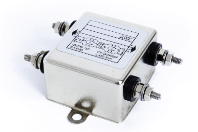
A noise filter is an electronic component used to remove noise from a power supply or signal.

It is used in many electric and electronic circuits. When the current value in a communicating cable changes, a magnetic field is generated in the surrounding area. This magnetic field generates noise (abnormal signals) in the surrounding cable.

Noise filters can be installed to prevent the generation of noise. Note that using a device without noise filtering may cause malfunctions or failures.

Uses of Noise Filters

Noise filters are widely used in acoustic and industrial equipment.

The following are examples of noise filter applications:

  • Prevention of noise in speakers
  • Prevention of noise inside radio equipment
  • Power supply lines of PLCs, PCs, and servers
  • Inverter power circuits and thyristor power circuits

Noise filters are mainly used for receiving equipment that want to avoid noise and for output equipment that generates noise. Speakers and radios are devices that you want to eliminate the effects of noise, and noise filters are attached to communication lines. In this case, noise is a source of noise.

Computers such as PLCs also want to avoid malfunctions caused by noise, so noise filters are sometimes attached to power supply lines and so on. On the other hand, inverters and thyristors are devices that generate noise.

Since current and voltage changes in the secondary side circuit may be steep, noise filters are used to remove generated noise by smoothing it out. When smoothing the generated current, a reactor is generally used.

Principle of Noise Filters

Noise is transmitted in two main ways: radiation noise, which is radiated directly into space from inside electronic equipment, and conducted noise, which is transmitted through power supply lines and electronic circuit wiring and causes interference to other electronic equipment. It is generated as noise, for example, when radio waves of different wavelengths are introduced into radio waves of various wavelengths.

To prevent this noise, a filter (low-pass filter) is used to cut high-frequency signals if the main cause of the noise is high frequency. On the other hand, if the noise is low-frequency, a filter that cuts low-frequency signals (high-pass filter) is used.

Inductors and capacitors are the most common types of filters that act as low-pass filters. An inductor has a low impedance for low-frequency signals and a high impedance for high-frequency signals. Therefore, inserting an inductor in series in a circuit, allows low-frequency signal components to pass through more easily, while allowing high-frequency components to pass through less easily.

Capacitors, on the other hand, have the opposite characteristics of inductors. Combining a capacitor and an inductor makes a noise filter that cuts low and high frequencies.

How to Select a Noise Filter

Two important factors in selecting a noise filter are the rated voltage and the rated current.

1. Rated Voltage

Use a voltage lower than the rated voltage (maximum operating voltage) specified for each product. Some manufacturers take voltage fluctuations into account and may allow the use of a voltage higher than the rated voltage.

2. Rated Current

As with voltage, each product has its own upper limit for current. In particular, current characteristics tend to change depending on the ambient temperature, so it is necessary to check the environment in which the product will be used in advance.

As the ambient temperature rises, the allowable load current gradually decreases. Although a current in excess of the allowable current will not cause a serious problem for a short period of time, repeated current flow may cause a failure. In addition, DC power supplies, etc., may generate inrush currents, and noise filters should be selected by considering the current value and duration of the inrush current.

Other Information on Noise Filters

Precautions for Using Noise Filters

Ground wiring is also important for noise filters. The ground wiring should be as thick and short as possible. If the ground wire is long, an inductance component will act on it, which may degrade the attenuation characteristics.

It is also important not to tie input/output wires together or wire them close together. If the input/output wiring is close together, high-frequency noise components will bypass the filter and the desired filtering effect will not be achieved.

カテゴリー
category_usa

Motion Controller

What Is a Motion Controller?

Motion Controllers

A motion controller is a device that controls the motion of equipment driven by servomotors or other devices.

The user programs the motion to be realized in advance, and the motion controller executes it to control the motion of the equipment.

Uses of Motion Controllers

Motion controllers are used to control equipment driven by servomotors or linear motors. Therefore, they are applied to industrial robots and machine tools.

Specific applications are as follows:

  • For control of cooperative robots
  • For control of packaging machines for general consumables
  • For control of commercial printing machines
  • For control of high-speed press machines
  • For control of automatic assembly robots

Principle of Motion Controllers

The principle of motion controllers differs depending on the output method.

Typical output methods are as follows:

1. Common Pulse Method

The common pulse method controls a motor with a rotation direction signal and a pulse driving command. The rotation direction signal controls forward and reverse rotation direction, and the pulse driving signal drives the motor.

2. 2-Way Pulse Method

The 2-directional pulse system is a system that controls the motor with two commands: an FWD pulse operation command and an REV pulse operation command. The motor is driven forward by an FWD pulse operation command and reversed by an REV pulse operation command.

3. Phase Difference Input Method

The phase difference input method determines the direction of rotation based on the phase difference between two pulse signals. Forward rotation is made when the reference pulse signal advances  90° and reverse rotation is made when the reference pulse signal lags 90°.

How to Select a Motion Controllers

Interpolation control is important when selecting a motion controller. Interpolation control is a method of synchronized control between multiple axes. There are two types of motion controllers: direct interpolation and circular interpolation.

1. Linear Interpolation

Linear interpolation is a control in which two motors are controlled simultaneously to move linearly to the desired position. The CPU performs calculations and control so that the motion moves in a straight line in a diagonal direction, rather than moving horizontally and then vertically. Since linear interpolation enables a linear move in the diagonal direction, the time required for positioning can be shortened.

2. Circular Interpolation

Circular interpolation is a control method in which the CPU calculates the movement to draw a circular arc when two motors are controlled simultaneously. Since the movement path is not linear, it takes longer to reach the target position than with linear interpolation. However, by using arc interpolation, it is possible to avoid obstacles on the route.

Other Information About the Motion Controllers

1. Features of Motion Controllers and PLCs

Motion controllers are similar to PLCs in that they automatically control equipment with user-custom programs. Motion controllers are unique in that they are better suited to control servo systems.

Motion controllers are often used for motion control instead of PLCs. One advantage of motion controllers is that they are suited for controlling multiple axes and synchronization when the total number of axes is large.

While PLCs are limited in the number of axes that can be controlled by a single PLC, motion controllers can control far more axes than that. For this reason, motion controllers are used in industrial machine tools and robots that require precise, multi-axis control.

2. Motion Controller and PLC Programming

The principle of PLCs and motion controllers differs in the method of processing in the CPU: PLCs are multitasking controllers that read all lines of the program each time they are executed and execute all lines at once. Therefore, the time required to read all lines of the program is the rate-limiting factor, and not enough computing time is available to perform complex control operations.

Motion controllers differ from PLCs in that the program is read and executed one line at a time. Therefore, compared to PLCs, the arithmetic processing required for one task is shorter, enabling high-speed processing.

In addition, the processing time of a single line of a motion controller is not affected by the increase in program capacity. Therefore, motion controllers can process complex systems such as servo motors at higher speeds.

カテゴリー
category_usa

Heater

What Is a Heater?

Heaters
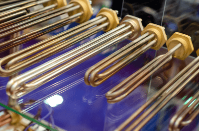
A heater is a general term for any device that generates heat.

The type that generates radiant heat by burning fuel is inexpensive and is widely used in home appliances. They are also indispensable devices for processing and assembly in industry.

Uses of Heaters

Heaters are used in a wide range of applications, from household appliances to industry. The following are examples of heater applications.

1. Heaters for Panels

In cold regions with sub-zero temperatures, the internal parts of control panels often experience dew condensation or freezing. Heaters for control panels may be used to maintain a constant internal temperature. Space heaters are also synonymous and are often installed inside generators and other equipment. 

2. Piping Heaters

These heaters are used to prevent freezing of water pipes, etc. They are also called anti-freeze heaters, anti-freeze belts, or trace heaters. Tape heaters and belt heaters are mainly used. 

3. Industrial Heaters

These heaters are used to heat raw materials and products for industrial purposes. The principles used vary, and non-contact heaters such as induction heating and dielectric heating are also used.

Applications vary and include bearing heaters for bearing mounting and dismounting of rotating equipment. Extruders and molding machines use cast-in heaters, for example.

4. Household Heaters

These heaters are used in homes for heating and other purposes. Typical examples are air conditioners and fan heaters. Ceramic heaters are sometimes used. Microwave ovens and toasters used for cooking are also heaters.

Principles of Heaters

Heaters heat objects according to various principles.

The following are examples of the heating principles of heaters:

1. Resistance Heating

Resistance heating is a method of generating Joule heat by passing an electric current through a resistance. Nichrome wire is used as the heating element. The heating element is placed in a metal sheath, such as a pipe, and the space between the sheath and the pipe is often filled with an insulator.

2. Induction Heating

Induction heating is a method of heating an object by generating and changing magnetic flux with a coil, thereby generating eddy currents. Typical applications include induction heaters for cooking. Although non-contact heating is possible, the object to be heated is mainly a conductive material.

3. Dielectric Heating

This is a method of heating by applying a high-frequency voltage, which shakes molecules and generates frictional heat. Microwave ovens are an example of dielectric heating. It is a non-contact heating method used to heat non-conductive materials.

4. Heat Pump

A heat pump heats by exchanging heat with a heat source and typical examples are air conditioners and water heaters. Air conditioners, for example, add heat to a room by heating the indoor heat exchanger with condensation heat from a compressed refrigerant.

Types of Heaters

There are various types of heaters, classified by the cause of heat generation and application. They are also classified by the method of heat conduction. Heating methods based on resistance heating include convection, conduction, and radiation.

1. Convection Heaters

This method directly heats the air and convects it. There are some disadvantages, such as dryness and dust caused by the warm air. However, it is characterized by the fact that it warms up quickly. Oil fan heaters and ceramic fan heaters are available.

2. Conduction Heaters

This is a method in which heat is transferred by direct contact. Only the part in contact can be warmed. It is characterized by lower power consumption than the convection method. Hot carpets and electric blankets are examples.

3. Radiant Heaters

This method heats by emitting infrared rays and heat, which are electromagnetic waves. It is characterized by a warmth that comes from the air and is quiet. Carbon heaters and oil heaters are available.

Other Information on Heaters

Energy-Saving Technology for Heaters

Effective use of heaters by reducing their energy consumption leads to energy savings. Generally, energy-saving techniques are used by using heat shielding sheets and insulation materials to keep heat outside. In some cases, temperature control by means of voltage control, etc., contributes to energy conservation.

Advanced temperature control also contributes to improved working environments and product processing accuracy. When the heating target is a liquid, such as water or oil, temperature control is required according to the characteristics of the liquid and the target temperature. When heating solids, temperature control is an important factor in quality.

カテゴリー
category_usa

Ferrite

What Is a Ferrite?

Ferrites

A Ferrite is a ceramic composed mainly of iron oxide and is used as a magnetic material.

Because it is ceramic, its electrical resistance is higher than that of metallic magnetic materials and is characterized by excellent corrosion and chemical resistance.

Uses of Ferrites

Ferrites are mainly used as a magnet called ferrites magnet. Because it is inexpensive and can be mass-produced, its use fields are diverse, including home appliances, game consoles, and personal computers.

Ferrites are also used as the core of transformers and as a material to block electromagnetic waves in radio wave anechoic boxes and anechoic chambers. Ferrite particles are also used as carriers to carry toner in laser printers, etc. Ferrites are a magnetic material that permeates our daily lives.

Types of Ferrites

There are three types of ferrites as follows.

1. Spinel-Type Ferrites

Spinel-type ferrites are ferrites whose main component is Fe2O4. In the past (because its main component was iron oxide) it had to be heat-treated at a temperature of 800°C or higher to be produced.

In recent years, it has become possible to produce it at temperatures as low as 100°C by conducting the reaction in an alkaline solution. Spinel-type ferrites exhibit soft magnetic properties when mixed with additives such as manganese, cobalt, nickel, copper, and zinc.

2. Hexagonal Ferrites

Hexagonal ferrites are ferrites with the chemical formula M-Fe12O19 (M: Ba, Sr, Pb, etc.). It is hard ferrites that exhibit complex magnetism when barium or strontium is added.

3. Garnet-Type Ferrites

Garnet-type ferrites are ferrites with the same type of crystal structure as natural pomegranate stone and have the chemical formula Mg3Al2Si3O12. Garnet-type ferrites are soft ferrites that exhibit the same mild magnetic properties as spinel-type ferrites.

Other Information on Ferrites

1. Properties of Ferrites

  • Hard Ferrites: Hard ferrites have ferromagnetic properties that become magnetic once a strong magnetic field is applied and then remain magnetic.
  • Soft Ferrites: Soft ferrites have weak magnetic properties that develop magnetization when a magnetic field is applied and cease to be magnetic when the field is removed. It is characterized by its high magnetic permeability and is used in the cores of coils and transformers.

2. Mechanism of Noise Reduction by Ferrites

Ferrites are also used as a noise-reducing component. For example, EMI (Electromagnetic Interface) is a significant problem in high-speed communication signals such as USB, etc. EMI (Electromagnetic Interference) is not limited to communication lines but refers to unwanted electromagnetic noise emitted by electrical equipment.

In terms of EMI certification and quality assurance, electrical equipment is classified as Class A or Class B, and appropriate EMI countermeasures are required for each product. Usually, EMI countermeasures are taken at the time of circuit and pattern design, but ferrites may be used in the later stages of design and when development time is limited.

By wrapping the ferrites around the noise-generating harness, the impedance of the cable changes according to the magnetization of the ferrites, and as a result, the noise current can be reduced. However, reducing noise current means that high-frequency components are reduced. In other words, the ferrites function as a simple low-pass filter.

Thus, it is essential to keep in mind that reducing high-frequency components leads to signal distortion, which may cause waveform accentuation and, eventually, signal quality degradation. The noise reduction characteristics of ferrites are determined by their impedance, which varies depending on the ferrite’s material, size, and number of turns.

When the ferrite material is the same and when the exact size is used, the impedance generally increases with the number of turns N in the harness. Although the increase in impedance results in more powerful noise suppression, the number of turns should be selected according to the frequency band to be suppressed.

The cross-sectional area also affects the impedance, and as a rule,  ferrites with a smaller inner diameter and a larger outer diameter have a higher impedance. A wide range of ferrites are available as high-frequency countermeasure components. It is important to understand the characteristics of each and use ferrites with the appropriate characteristics for the frequency band to be counteracted.

カテゴリー
category_usa

Emulator

What Is an Emulator?

An emulator is a tool, either in software or hardware form, that replicates the functionality of another system. This replication allows the host system to run software or use peripheral devices designed for the emulated system.

Uses of Emulators

Software emulators enable applications designed for one operating system, such as Android OS, to run on a different operating system, like Windows OS. Hardware emulators, on the other hand, are often used in the development and debugging of software for devices with microcontrollers.

Principle of Emulators

The core principle behind emulation lies in the conversion of high-level or visual programming languages into machine language (binary code), which can be processed by hardware. All digital technology, including hardware circuits and peripheral devices, operates on binary logic. Thus, both software and hardware execute operations using 0s and 1s, albeit through different mechanisms.

Types of Emulators

1. Software Emulator

Software emulators allow applications developed for one platform to run on another, such as running Android applications on Windows OS. While they facilitate cross-platform compatibility, they may result in reduced operation speed due to the additional layer of emulation.

This category also includes browser emulators that enable web pages designed for one browser to be displayed in another, potentially affecting performance due to the emulator’s processing.

2. Hardware Emulator

The in-circuit emulator (ICE) is a prominent example used in microcontroller software development. It emulates the functionality of a microcontroller, providing terminals for external status monitoring, connection to external memory, and setting breakpoints for debugging purposes.

3. Other Hardware Emulators

Hardware emulators also facilitate the use of software on obsolete or malfunctioning computers, extending the life of legacy systems and applications.

Other Information on Emulators

1. Tips for Using ICE

Effective use of ICE requires programs that operate hardware components directly. While higher-level languages offer simplicity, C programming is preferred for microcontroller ROM due to its smaller code footprint and closer proximity to assembler language, enhancing real-time performance and hardware control.

2. Mixed Hardware/Software Emulator

A hybrid emulator, combining hardware and software elements, can emulate a complete computer system. This allows for the development and debugging of new operating systems on a simulated platform.

カテゴリー
category_usa

Ferrite Core

What Is a Ferrite Core?

Ferrite Cores
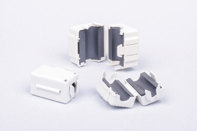
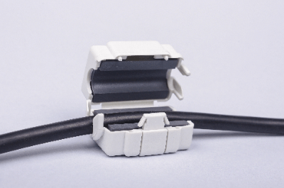
A ferrite core is a ceramic magnetic material called ferrite, which is mainly composed of iron, and is processed according to the application.

The use of ferrite as a magnetic core can block high-frequency currents, and is therefore effective as a noise suppressor. Ferrites are classified into different systems according to their composition, but Ni-Zn ferrites are mainly used for noise reduction.

The reasons for this are that the Ni-Zn type does not require insulation processing and has excellent high-frequency characteristics. Noise can be eliminated by passing a cable through a ring-shaped ferrite core.

Uses of Ferrite Cores

Ferrite cores are used for noise reduction in electronic equipment. The noise-reducing effect of ferrite cores is not limited to noise entering the cable from the outside, but can also eliminate noise generated by the cable itself.

Ferrite cores are simple, inexpensive noise suppression components and are characterized by their easy handling. Therefore, noise suppression can be implemented without the need for design changes to the board or circuitry. Therefore, they can be used as an experimental method before finalizing the final specifications or as an emergency noise suppression measure.

Principle of Ferrite Cores

There are two main principles by which ferrite cores can eliminate noise: First, they act as a filter to cut high-frequency frequencies and eliminate noise caused by high-frequency currents.

When electricity flows through the hole in the ferrite core, the cable becomes an inductor, and the impedance of the cable changes according to the magnetization of the ferrite core. At this time, the impedance becomes higher in the high-frequency band, enabling attenuation of high-frequency currents that are noise components.

319_Ferrite-Cores_フェライトコア-1.png

Figure 1. Ferrite Core Noise Removal

Second, hysteresis loss allows noise current to be dissipated as thermal energy. When an inductor is configured by a ferrite core and an alternating current flows through it, the generated magnetic field fluctuates in direction and magnitude with time in a certain period.

The magnetization of the ferrite core making one cycle is called a hysteresis loop, and the loss of energy that occurs during this process is called hysteresis loss.

How to Select a Ferrite Core

When selecting a ferrite core, there are some things to keep in mind.

1. When Cutting Noise in the High-Frequency Band Above 150 Mhz as a Rough Guide

  • The inner diameter of the ferrite core should match the cable, and the outer diameter should be as large as possible and the length should be as long as possible.
  • Use the cable without turning
  • Obtain good impedance characteristics due to the shape factor of the ferrite core

2. When Used to Cut Noise in the Sea Frequency Range Lower Than 150MHZ or as a Noise Suppressor for Cables in Equipment

  • Select a type of ferrite core with a larger inner diameter and shorter length
  • Use cable with turns
  • Obtain good impedance characteristics depending on the number of turns

Other Information on Ferrite Cores

1. Ferrite Core Material

A soft magnetic material called soft ferrite is used for ferrite cores. Oxides of transition metals such as nickel, iron, zinc, and copper are the main raw materials. Since the permeability of soft ferrite can be changed by its composition, the impedance can be tuned by the ratio of the main raw materials.

Impedance has two components, namely reactance and resistance. The material composition of a ferrite core for noise rejection contains a large amount of resistance component. Therefore, noise rejection is more effective in dissipating the energy of noise current as heat due to hysteresis loss than in filtering to cut high frequencies.

2. Noise Rejection Performance of Ferrite Cores

The noise rejection performance of a ferrite core is evaluated by its impedance. Impedance is determined by material properties, shape factor, and number of turns.

The material properties are determined by the composition of the soft ferrite. The shape factor is the cross-sectional area of the ferrite core divided by the average magnetic path length. Therefore, a ferrite core with a large cross-sectional area and a small inner diameter performs better. For better noise rejection, wrapping the cable around the ferrite core multiple times is also effective.

However, when a conductor is wound more than once, the beginning and end of the winding are close to each other, creating stray capacitance between them. Since this stray capacitance reduces the effectiveness of countermeasures against high-frequency components, it is necessary to wind the cable while keeping an eye on the frequency band for which noise reduction is desired.

カテゴリー
category_usa

Terminal Block

What Is a Terminal Block?

Terminal Blocks

A terminal block is a row of terminals that connect external wiring to internal circuits. They are used in distribution boards and power distribution boards.

Electric wires are treated with crimp terminals and fixed to the terminal block. Screw-fastening and screwless types are available for terminal blocks.

Two-stage types and oil-and chemical-resistant types are also available. Voltage and continuity can be measured on the terminal block using a tester.

Uses of Terminal Blocks

Terminal blocks are used to connect circuits inside the panel to external wiring. Terminal blocks are used in distribution boards, switchboards, breakers, noise filters, aerospace, relays, air conditioning controls, and more.

Depending on the application, there are many types of terminal blocks to choose from. For example, for interface use, there are dedicated interface terminal blocks that are compact and convenient with many terminals. In addition, terminal blocks for grounding, fuses, and other applications are available.

Principle of Terminal Blocks

Terminal blocks are divided into conductive boards and components such as plastic girders.

Conductive boards are made of conductive materials and are used to conduct electric current between wires. The plastic frame is the part that insulates the electric circuit to prevent ground faults.

Crimp terminals are used to connect the conductive plate to the wires. Although crimp terminals alone may be used, it is safer to protect them from electric shock with marked tubes or insulating caps.

The crimp terminal is clamped under the screw attached to the conductive plate. The current can flow through the conductive plate. Generally, do not fasten more than three wires to a single screw. The purpose is to prevent increased contact resistance.

Do not allow wires to ride on top of equipment or fixtures to avoid electric shock or ground fault. Before use, check the specifications of the terminal blocks to ensure that the current and voltage are within the allowed range.

Screwless types are convenient because they do not require terminals and can be used by stripping the wires and inserting them directly into the terminal blocks.

Resin mounts are available in thermoplastic and thermosetting resins, which differ in heat and chemical resistance. Screws and conductive plates are made of copper, stainless steel, chrome plating, or other conductive metals, and many products are RoHS compliant.

Types of Terminal Blocks

Apart from the classification of connection methods, there are convenient terminal blocks with various functions.

1. Common Terminal Blocks

Standard terminal blocks, in which each terminal connection is connected internally, are mainly used for power distribution. 10-circuit, 20-circuit, plug-in type, screw connection, and other types are available and are selected according to the specifications of the equipment.

2. Connector Terminal Blocks

Connector terminal blocks are used to convert connectors of various standards into terminals. Connectors are connected to terminal blocks, and wires are connected to the terminals corresponding to the connector pins without soldering.

Many connectors can be used, and products compatible with various connectors such as D-Sub, MIL, and FCN are available. Terminal connections are also available with screw connections, plug-in types, etc.

Connector terminal blocks are often used for IO connections to PLCs; I/O can be input/output to PLCs by connecting the IO connector of the PLC to the connector terminal blocks with a cable and wiring I/O to the terminal blocks, thereby reducing wiring person-hours.

カテゴリー
category_usa

Automotive connector

What Is an Automotive Connector?

Automotive Connectors
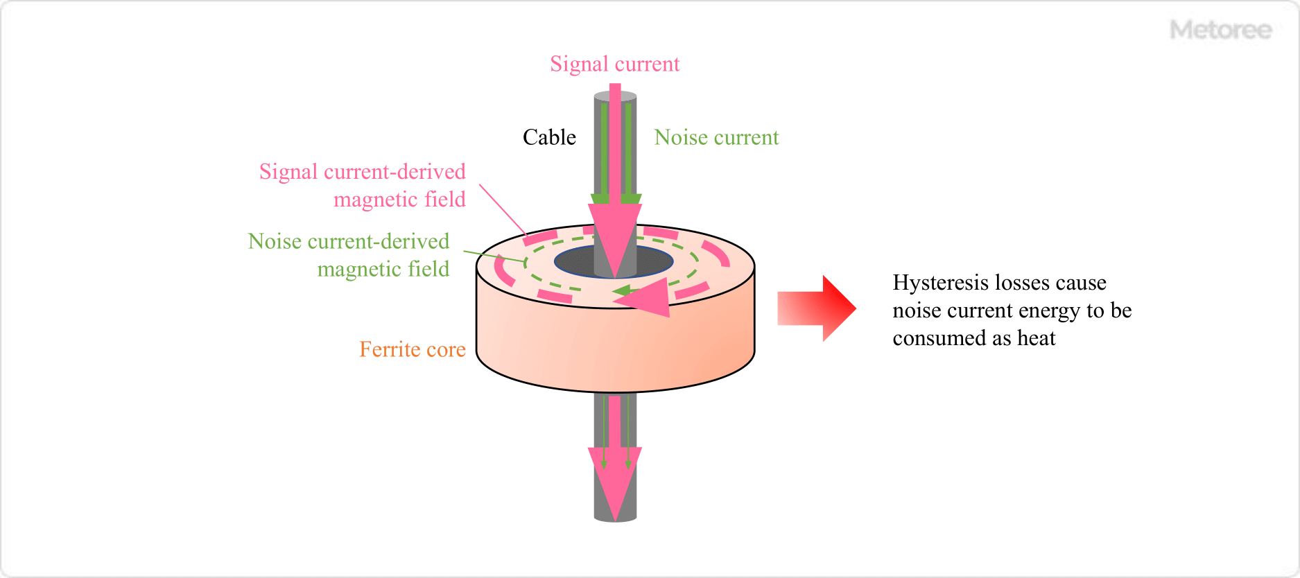
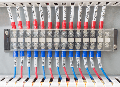
Automotive connectors are components used exclusively in automobiles to connect automotive wiring.

As automobiles become more sophisticated with advanced communication functions and higher performance, the number of electronic circuits and components increases, and many types of in-vehicle connectors are being developed. In addition, electric vehicles are now being sold, and special connectors are being used for charging and discharging.

There are many types of in-vehicle connectors that can be adapted to the sensors and environments of humidity, temperature, vibration, and water installed in automobiles. There is a lineup from minute signals in the wiring to be connected to high power applications.

Uses of Automotive Connectors

Since connectors used for wiring in automobiles in general are called automotive connectors, there are many types of connectors, including harness connectors, FPC connectors, board-to-board connectors, and coaxial connectors. The intended use differs depending on the type.

  • Harness Connectors
    Safety systems, high voltage, waterproof, advanced driving systems, etc.
  • FPC Connectors
    Advanced driving systems, multimedia
  • Board-To-Board Connectors
    Advanced driving systems, ECUs
  • Coaxial Connectors
    Advanced driving systems, multimedia, ECUs

Principles of Automotive Connectors

Since automotive connectors serve to connect wires together, their structure is basically the same as that of general connectors. Connectors are divided into two main parts. The contacts, which electrically connect the wires to each other, and the housing, which is an insulator that incorporates the contacts.

In the case of automotive connectors, many connectors are equipped with a mechanical lock to prevent poor contact or disconnection due to vibration. When the plug is pushed in, a clicking sound is heard, and the connector is securely locked. Other connectors have a structure that allows secondary engagement with a housing lance and retainer to prevent the contact part from falling out.

In addition, products with materials and structures suitable for the environment of the location where in-vehicle connectors are used are used. For example, connectors for charging and discharging electric vehicles are designed to provide adequate waterproof protection, and the outer plastic of such connectors is made of a weather-resistant and strong enough plastic to prevent deterioration and impact damage.

Other Information on Automotive Connectors

Applications of Automotive Connectors

1. Automotive Waterproof Connectors
Waterproof connectors are used in places where waterproofing or dustproofing is required. Specifically, they are used around the engine compartment where water and oil are generated, around floor mats where water from wet shoes can seep in, and in places where water may enter during rainy weather. Compared to ordinary connectors, the structure is significantly different, and waterproofing measures range from external measures as water-repellent treatment of the case to a single terminal inside the connector.

A seal ring is used on the terminal inside the connector to fill the gap that occurs during mating, preventing water, oil, and dust from entering from the outside. In addition, the part where the wire connects to the terminal is fitted with a rubber plug that is tightened to provide environmental resistance as well as resistance to external forces, such as pulling.

Connectors used around engines have a structure that can withstand high temperatures and vibration in addition to waterproofing. Due to their complex structure and high environmental resistance, automotive waterproof connectors are much more expensive to produce than normal automotive connectors, with a difference of several, to dozens of times the cost.

2. Automotive Connectors for Safety Components
Automotive connectors are sometimes used for components that require strict management from a safety standpoint, such as airbags, collision detection sensors, and ECUs (electronic control units). Since airbags directly affect human lives, high reliability is required, and in addition to waterproofing, measures are taken to prevent under-insertion and un-mating when mating connectors.

A double mating structure with two parts, a retainer and a front cap, prevents unmating. The retainer and front cap cannot be installed unless the connector is securely mated. This prevents insufficient insertion during mating.

In addition, measures are also taken to prevent incorrect mating by the operator during the assembly process. The shape and color of the connector are significantly different from those of standard connectors, making it possible to identify errors at a glance. The color of connectors used for airbags, an important safety component, tends to be yellow.

3. Onboard Connectors Used for High-Voltage Components
Connectors such as those used for charging and discharging electric vehicles require high voltages to shorten the time required for charging and discharging. When used for high-voltage components, they require higher safety performance than ordinary connectors, including measures to prevent electric shock and ignition due to a rise in the generated temperature.

In addition, since it is assumed that consumers will be able to charge the batteries themselves, robustness and light weight are required. Standards have been established to ensure that these safety features do not vary, and by complying with the standards, connectors from any manufacturer can be used, as long as they are compatible across manufacturers as long as they comply with the same standards.

4. In-Vehicle Connectors for Use in Advanced Driving Systems
In-vehicle connectors used for advanced driving systems need to be able to monitor the location of surrounding vehicles, people, motorcycles, and other objects while moving, so they must have high-speed communication performance to prevent communication loss.

In addition, many types of communication can take place in a car, such as smart phone signals, TV reception, etc. Therefore, noise immunity performance is required to prevent malfunctions caused by these communications and to prevent malfunctions in the surrounding communications. To improve high-speed communication performance and noise immunity, shielded components are indispensable to protect signal lines.