カテゴリー
category_usa

SAW Filter

What Is a SAW Filter?

A SAW (surface acoustic wave) filter is a device designed to selectively pass or block electrical signals at specific frequencies. It utilizes mechanical vibrations of surface acoustic waves on a piezoelectric element to achieve steep frequency selectivity. These waves, traveling across the surface of the medium, rapidly attenuate as they move deeper, enabling precise filtering.

Electrical signals input into a SAW filter are converted into mechanical vibrations by the piezoelectric element, which then selectively filters and outputs the desired frequency back as an electrical signal.

Uses of SAW Filters

SAW filters are commonly found in duplexers for wireless communication devices like smartphones, TV tuners, and wireless LANs. Their low loss, excellent cutoff characteristics, affordability, and compact, thin profiles make them essential for mobile device functionality. As mobile devices use an increasing number of communication frequency bands, SAW filters play a crucial role in band selection and wireless communication technology.

Principle of SAW Filters

SAW filters operate by converting high-frequency electrical signals into mechanical vibrations across a piezoelectric substrate with comb-shaped electrodes. These vibrations, resonating through the electrodes, generate surface waves that propagate back to detection electrodes, where they’re converted back into electrical signals. The filter’s performance is influenced by the piezoelectric material’s properties and the electrode structure, as the propagation speed of surface waves varies with the material used.

Other Information on SAW Filters

1. The SAW Filter Market

The SAW filter market is expanding to meet the increasing demands of smartphone transmission capabilities, with innovations in carrier aggregation and MIMO technologies. The need for filters in FDD modulation schemes, which transmit and receive simultaneously, is growing, especially for high-end models requiring global availability. Japanese manufacturers are notably prominent in the SAW filter market.

2. Difference from BAW Filters

While SAW filters utilize surface acoustic waves on piezoelectric substrates, BAW (bulk acoustic wave) filters operate differently, employing either FBAR (film bulk acoustic resonators) or SMR (solidly mounted resonators) principles. SAW filters are cost-effective for frequencies up to 2 GHz, whereas BAW filters, more complex and expensive, offer higher Q and sharper filter characteristics for higher frequency bands.

3. SAW Filters and 5G

In the 5G era, especially for the 3-6 GHz band, BAW filters become crucial due to their ability to handle steep and high Q-value filter characteristics required for coexistence with WiFi and addressing increased losses at higher frequencies. U.S. manufacturers like Broadcom and Qorvo lead in the BAW filter market.

カテゴリー
category_usa

Fuse Holder

What Is a Fuse Holder?

Fuse Holders

A fuse holder is a device used to attach a fuse to an electrical circuit.

It consists of a clamp for fixing and a terminal for connection to the electric circuit. They are designed to allow easy replacement of fuses.

Fuses are used to prevent equipment failure due to overcurrent. Fuses are suitable for different materials and blending conditions, and are selected according to the situation.

Uses of Fuse Holders

Fuse holders are widely used to improve the protection of electrical circuits. The following are examples of fuse holder applications:

  • Televisions and other home appliances.
  • Household or industrial lighting fixtures.
  • Automotive audio and ETC in-vehicle devices.

Many home appliances also use fuse holders, which ensure safety by blowing a fuse to protect the electrical circuit in the event of a malfunction. Fuse holders are also widely used in automotive products to protect the vehicle’s electrical circuits, often in LED lights and high-precision electronic circuit boards.

Principle of Fuse Holders

The principle of fuse holders is closely related to that of fuses. Fuses are in a low resistance state to energize a circuit under normal conditions. However, if the current becomes abnormally high, thermal expansion of the fuse can cause it to blow, interrupting the circuit.

Fuse holders are devices used to secure these fuses to the circuit. It has a clamp for attaching the fuse and a terminal for connecting the electrical circuit.

The fuse is inserted into the fuse holder connected to the circuit. There are a variety of fuse holders available, and the size is selected according to the size of the fuse.

Types of Fuse Holders

There are various types of fuse holders for different situations. The following are examples of fuse holder types:

1. Panel Mount

Panel-mount fuse holders are used by attaching them to the panel. The panel-mount-type is generally fixed to the panel by drilling holes, and the fuse inserted. There are various types of panel-mounted fuse holders available, including those with mounting screws and those that are secured to the panel with clips.

2. In-Line Fuses

These fuse holders are used directly in electrical circuits. There are a variety of line-ups, such as types that inserts a fuse and types that can be turned on and off like a switch. Inline types also offer a variety of connection methods such as through-holes and wire leads.

3. Through-Hole

This is a fuse holder with a hole-shaped fuse holder terminal. Since the fuse is installed through a through-hole, the contact area between the fuse and fuse holder is large. Therefore, it has the advantage of low contact resistance and high reliability.

4. Clip Type

This type of fuse holder uses a clip to hold the fuse in place. Instead of inserting the fuse, the clip is opened and the fuse is inserted between the clip and the fuse. The advantage is that the fuse can be easily removed and replaced.

5. Fuse Box

A box-shaped fuse holder for storing fuses. The box for storing fuses and the terminals that connect the fuses to the electrical circuit are integrated. Because they are dustproof and waterproof, they are suitable for outdoor use.

How to Select a Fuse Holder

When selecting a fuse holder, consider the size, type, current rating, and connection method.

1. Size

First, you must select a fuse holder that matches the size of your fuse. Since fuse holders are used to mount fuses, size matching is essential.

2. Type

It is also necessary to select appropriate products from a wide variety of types. Select the correct fuse holder for each type of fuse. If the fuse and holder are mismatched, they cannot be properly introduced into the electrical circuit.

3. Current Rating

Next, select the rated current, choose the appropriate fuse for the current, and install it in the fuse holder.

4. Connection Method

Depending on the type of wiring to be connected to the terminal part of the fuse holder, select a fuse holder with an appropriate connection method.

カテゴリー
category_usa

Linear Motion System

What Is a Linear Motion System?

Linear Motion Guides

A linear motion system is a mechanical element that guides parts by reducing friction in linear motion.

To reduce friction, metal balls are generally used. Some use rollers or high-performance engineering plastics. The balls roll between the conveyor platform and the straight rail and move on the rail while supporting the weight. The balls can circulate on the conveyor table.

Linear motion systems allow smooth movement with little force. The precision-machined guide rails and balls have a little rattle, and the rotation of the balls is accurately transmitted to the transfer table, resulting in high positioning accuracy. Since the linear motion system have no propulsive force, it is used with ball screws, cylinders, or other mechanisms to move the transfer table in any direction.

Uses of Linear Motion Systems

Linear motion systems are used where precise linear motion is required. They are used in machine tool tables, conveying equipment, inspection machines, robots, etc. They are also used in wood processing machines, construction machinery, and automated machinery. Rolling of linear motion parts improves machine performance, such as higher precision, higher speed, and labor-saving in mechatronics equipment.

Its use is expanding to include liquid crystal manufacturing lines, railcars, welfare vehicles, medical equipment, seismic isolation and vibration control devices for high-rise buildings and housing, amusement equipment, drones, and printers. When precise linear motion is required, two guide rails are used. The mounting surface of the linear motion systems must be precisely machined.

Principle of Linear Motion Systems

Linear motion systems consists of a guide rail, a carriage block, balls, ball retainers, and return caps. The guide rail is attached to the structural member, and the conveyor block moves on the guide rail with the rolling motion of the balls.

The rolling surface of the guide rail has a groove with a radius similar to the ball’s diameter. Contact between the rolling surface and the balls is reduced from point contact to surface contact, greatly improving the allowable load and life. The structure of multiple rows of strips to support the ball enables accuracy to be maintained even under severe operating conditions, such as moment loads during rapid acceleration/deceleration and long continuous operation.

It is necessary to prevent unevenness in operation due to changes in the distance between the balls caused by their rolling during operation. Therefore, retainers are provided to keep the distance between the balls constant during operation. Linear motion systems are classified according to the accuracy of the balls and guide rails.

The higher the accuracy grade, the more restricted the operating environment, so it is necessary to calculate the load and consider the rated life before use. Some guide rails have offset gothic arch grooves in which the balls roll. They have the advantage of high static load capacity.

Types of Linear Motion Systems

There are two types of linear motion systems, the miniature type and the medium/heavy load type.

1. Miniature Type

This type consists of two rows of balls that contact the guideway raceway at four points. This type is used in situations where no particularly heavy load is applied. 

2. Medium to Heavy Load Type

This type consists of four rows of balls that make contact with the guideway raceway at two points. This type is used for machine tools that perform heavy-duty cutting. The allowable load is increased by providing a groove for the balls to roll on the guideway.

3. Other Types

Some types do not use balls. Rollers, high-performance enplanes, oil-less metal, etc., are used for sliding parts. Compared to the ball type, this type has a larger load capacity and is more resistant to dust and other foreign matter. The disadvantage is the high frictional force.

Furthermore, in addition to straight rails, there are other types, such as cross guides and R guides. If high rigidity is not required, there is a compact, lightweight, and low-cost precision ball slide made by precision forming a stainless steel sheet into a U-shape and integrating the raceway portion and mounting surface.

Other Information on Linear Motion Systems

Features of Linear Motion Systems

Circulating ball-type linear motion systems are characterized by high rigidity, long life, high accuracy, quiet and smooth operation, and excellent vibration characteristics. Sliding-type linear motion systems that do not use balls are up to about 40% less expensive than ball-type linear motion systems. They are maintenance-free, lubricant-free, resistant to dust and moisture, have excellent corrosion resistance, are hygienic, have low noise, are lightweight, and have other advantages. 

カテゴリー
category_usa

Infrared LED

What Is an Infrared LED?

An infrared LED, or IR-LED or Ir-LED, is a light-emitting diode that produces infrared light. The term “IR” stands for “Infrared,” indicating light with a wavelength longer than visible red light. LEDs emit light when voltage is applied, making infrared LEDs capable of emitting near-infrared light within the 700 to 1,500 nm wavelength range.

Infrared light, characterized by its high transparency and minimal obstruction by obstacles, is invisible to the human eye. This makes it ideal for signal transmission/reception and as a light source for various sensors. Despite the availability of other infrared light sources, such as lasers, infrared LEDs are distinct for their mass production capability, longevity, resistance to shock, and cost-effectiveness.

Uses of Infrared LEDs

Infrared LEDs find applications across daily life and specialized fields, including:

  • Remote controls for TVs and air conditioners
  • Security camera lighting
  • LiDAR and TOF camera light sources
  • Moisture measurement in samples
  • Night vision camera lighting
  • Distance measurement devices for golf
  • Smartphone and cellphone communication

Among the most common applications are remote controls for TVs and air conditioners, chosen for their ability to operate undetected by humans without adverse health effects. Additionally, “LiDAR” (Light Detection And Ranging) employs infrared LEDs for distance sensing, crucial for the development of autonomous driving technologies.

Principle of Infrared LEDs

The fundamental principle of LED light emission, applicable across all wavelengths, involves the p-n junction of semiconductors. Upon application of an electric field, holes migrate through the p-type semiconductor, while electrons move through the n-type semiconductor. The energy gap between the electrons and holes facilitates their collision upon perturbation, resulting in light and heat production. By varying the semiconductor composition, the emission wavelength can be tailored. Aluminum gallium arsenide (AlGaAs) is commonly used for near-infrared wavelengths, although infrared LEDs typically exhibit lower efficiency compared to their visible light counterparts.

Other Information on Infrared LEDs

1. Infrared LED Lights

Commercially available infrared LED lights cater to various applications, including night vision. Floodlights illuminate outdoor areas at night, employing multiple high-output infrared LEDs. Similarly, infrared LED flashlights, lightweight and sometimes featuring adjustable light quantities, support night activities. Compact night vision lights, designed for photography, ensure even lighting with a single high-output LED, boasting portability with lightweight designs and AA battery operation.

2. Infrared LED Tape

Infrared LED tape, designed for night vision camera auxiliary lighting, integrates infrared LEDs at regular intervals. Its adhesive backing facilitates easy application, with types available for confined spaces measuring 3 mm or thinner, offering versatility in use.

カテゴリー
category_usa

Insulated Gate Bipolar Transistor (IGBT)

What Is IGBT?

Insulated Gate Bipolar Transistors (IGBT)

IGBT is an insulated gate bipolar transistor. The name is shortened to IGBT. 

An equivalent circuit can be considered a composite transistor circuit configuration with an N-channel MOSFET at the input and a PNP-type bipolar transistor at the output. On the other hand, since the structure can be said to have a MOSFET in the base of the bipolar transistor section, it can generate a very large output current for a small current.

It is a high-performance semiconductor with a higher breakdown voltage and lower loss than the MOSFET that serves as the base. IGBT was developed in Japan in the 1980s, and its structure at that time was called a punch-through type.

In recent years, as wafer processes have progressed, IGBT devices have become smaller and less expensive, and non-punch-through and field-stop IGBT devices are now being manufactured.

Uses of IGBTs

IGBTs are commonly used in variable-speed drives and power converters due to their high speed under high-power operating conditions.

They are also used extensively in inverter circuits for induction cooktops, washing machines, and air conditioners, as well as in the power control of large home appliances such as printers. With the recent trend towards energy conservation, the use of IGBTs, which can reduce power loss, is further expanding.

Principle of IGBTs

IGBTs have the structure of a MOSFET at the input and a bipolar transistor at the output, as explained at the beginning of this article, and have characteristics that are a combination of the features of each.

Because of the two types of carriers, its switching speed is slower than that of a MOSFET but faster than that of a bipolar transistor, and its withstand voltage is improved over that of a MOSFET. When voltage is applied from the gate, which is the input part of the terminal, current flows from the MOSFET and conducts to the P-type semiconductor, which in turn amplifies a small amount of current, as is the nature of bipolar transistors, allowing a large current to flow between the emitter and collector.

In addition, conductivity modulation occurs as in a bipolar transistor so that on-resistance can be lowered and current density can be increased. Since a constant voltage drop occurs between the collector and emitter, losses can be lower than with MOSFETs when the current is high.

Other Information on IGBTs

1. About Inverter Circuits Applying IGBTs

An inverter circuit is a DC-to-AC conversion circuit used in pairs with an AC-to-DC converter circuit. IGBTs are used in this inverter circuit to output AC with a different voltage and frequency.

IGBTs are switched to adjust the on/off interval and pulse width. By generating and shaping different pulse waves, the pulse wave is made closer to a sine wave. This is called pulse width modulation, and IGBTs are often used here.

The functions of home appliances are controlled by changing the speed of the motor through frequency conversion by pulse width modulation. IGBTs are widely used in home appliances such as air conditioners, refrigerators, industrial motors, and computer power supplies. 

2. Difference between IGBTs and MOSFETs

IGBTs are often described as a combination of MOSFETs and BJTs (bipolar junction transistors), but they have some drawbacks when compared to MOSFETs. IGBTs have a rising voltage that has an offset due to their configuration, especially in the low-current range. In general, MOSFET devices have lower Vds than IGBTs, especially in the low current range.

IGBTs are mainly focused on the medium to the high current range, so they exhibit lower on-resistance than MOSFETs in this range. Still, for applications where efficiency in the low power range is essential, MOSFETs have better characteristics. = 2V, MOSFETs are superior in efficiency, while IGBTs are superior at higher voltages.

3. About IGBT Modules

IGBTs are complex devices, and it takes a lot of effort to assemble them so that their operation can be controlled from scratch. Therefore, IGBT modules that combine signal processing, amplification, protection circuits, parasitic diodes, and other components of the control part into a composite module are widely commercialized.

Since IGBTs are transistors that are prone to breakdown if their SOA (Safety Operation Area) or absolute maximum ratings are exceeded, some of them have built-in protection circuits. IGBTs were developed to achieve both withstand voltage and switching speed and have been improved over the years. In this power device area, power semiconductor devices using new compound semiconductor materials such as SiC and GaN have recently begun to be introduced.

These next-generation power semiconductor devices enable faster-switching operations than IGBTs and have superior breakdown voltages, so research and development of these devices have been increasingly active in recent years. However, there are still issues to be cleared, such as cost and supply, and they are not expected to replace the entire current IGBTs market area. 

カテゴリー
category_usa

Clamp-On Meter

What Is a Clamp-On Meter?

Clamp-On Meters

A clamp-on meter is an instrument that measures the current flowing in a circuit.

Ordinary ammeters must be built into the current circuit, and the circuit must be stopped once. On the other hand, a Clamp-on meter can measure current by simply clamping the wire section from the outside. The work can be done quickly and safely without the need to interrupt the circuit.

Uses of Clamp-On Meters

Clamp-on meters are used in situations where the value of the current flowing in a circuit needs to be determined simply. The following are examples of use.

  • Pre-checking and post-checking of current flow during electrical work
  • Checking the energized part of an electric circuit to investigate the cause of a breakdown
  • Checking the operating status of electric equipment

Another feature of clamp-on meters is that they can be used without power interruption. It can be applied to equipment in continuous operation.

Principle of Clamp-On Meters

Clamp-on meters do not measure the current but measure the magnetic field generated by the current and output it as a current equivalent value.

The clamp part of the clamp-on meters has a magnetic core that detects the magnetic field and converts it to a current value. Since the polarity of the magnetic field differs between AC and DC, the principle is different.

Among the various measurement methods, the Hall element method can detect both DC and AC. In this method, a Hall element is built into the magnetic core to measure the magnetic field of the circuit under test as a voltage, which is converted to a current value via a built-in amplifier.

How to Select Clamp-On Meters

Current circuits include both DC and AC circuits. It is important to select an appropriate clamp-on meter according to the current component of the circuit you wish to measure and the accuracy at which you wish to measure.

If you do not require great accuracy, a Hall element-type clamp-on meter that can handle both DC and AC circuits is a safe choice. However, it is assumed that the clamp may not clamp well, depending on the installation position of the circuit.

For AC, select a Rogowski-type clamp-on meter without a core, which allows measurement while bending the clamping section.

Other Information on Clamp-On Meters

1. How to Measure Leakage Current

Leakage current is an essential inspection item in the maintenance of electrical equipment because it can cause electric shock. A leakage current clamp-on meter is used to measure leakage current.
The leakage current is a very small current, and the leakage current clamp-on meters are equipped with a sensitive current transformer. Permalloy, which has high magnetic permeability and is suitable for detecting minute currents, is used for the current transformer.

Leakage current is measured in two ways: “measurement of zero-phase current” and “measurement of earth line current.”

Measurement of Zero-Phase Current
In the measurement of zero-phase current, all phases are clamped together. The clamp-on meters detect the magnetic field caused by the current and convert it into a current value, but the magnetic fields caused by the current flowing against the load cancel each other out. However, if there is a leakage current, the magnetic fields become unbalanced, and a current value is displayed on the clamp-on meters. By reading this current value, the magnitude of the leakage current can be measured.

Measuring Ground Wire Current
Electrical equipment is grounded with a ground wire. In the event of leakage current, the leakage current flows through the ground wire to the earth, so the current value can be measured by directly clamping the ground wire.

2. Accuracy of Clamp-On Meters

There are two types of AC measurement methods: “average value type” and “effective value type”.

Average value type
In the average value type, the current value for a half cycle of AC is averaged, and the average value is multiplied by the waveform factor to obtain the measurement value.

RMS value type
In the RMS value type, the current value is periodically sampled and measured, and the RMS value is obtained by performing the RMS operation on the measured value.

In current measurement, if the current to be measured is a sinusoidal wave, the value is the same regardless of the measurement method. However, if the current to be measured is a distorted wave, the harmonic component prevents the average value type clamp-on meters from obtaining the correct RMS value.

On the other hand, RMS value-indicating clamp-on meters can be measured without any loss of measurement accuracy if the sampling frequency is sufficiently high. As described above, if the current to be measured contains distortion waves, RMS-type clamp-on meters should be used. However, inexpensive clamp-on meters are of the moving coil type of the average value type.

カテゴリー
category_usa

Visual Inspection System

What Is a Visual Inspection System?

A visual inspection system can inspect the appearance of mass-produced goods. For a large number of manufactured products, the introduction of equipment can improve productivity and reduce prices rather than human inspection.

The system inspects and instantly determines the appearance of foreign matter, dirt, burrs, cracks, breaks, and chips on the surface of manufactured parts and products. Processes for visual inspection include inspection at the manufacturing stage, after surface treatment, and after product assembly. Inspection by the equipment requires clearly defined standards, and a dot gauge is used to determine whether a product has passed or failed.

Uses of Visual Inspection Systems

The visual inspection systems are used in many areas of the manufacturing industry. Food packaging, bottles, electronic devices, medical devices, molded sheets, and many other industries produce so much that they could not keep up with production without visual inspection systems. Improvements in camera and image processing technology have made it possible to determine even the smallest foreign objects, scratches, and defects.

Specifically, it can detect differences in the shape of electronic components, rust, corrosion, and dents in bearings, as well as burrs, cracks, and deformation in bolts and screws. It can also detect burns, dents, and even scratches on food containers.

Principle of Visual Inspection Systems

The image processing inspection method is the most commonly used method for visual inspection. It consists of an image sensor such as a camera, an image processor, and software. The object is illuminated evenly and brightly, and a lens captures the image for inspection.

The system records the shading of each pixel in the image of many passed products in advance. The mean value and standard deviation of the difference in density are determined by dividing the image into certain sections, and the values are compared with the pixel value of the inspected object for each section. If the density differs significantly from that of the past product, it is judged as a flaw or foreign matter. The dimensional criteria for scratches and foreign matter are registered to determine whether the product has passed or failed the inspection. Differential or projection processing may be performed to prevent false positives.

In the case of circumferential objects, polar coordinate transformation processing is used to compare densities and make a judgment.

Image sensors are highly versatile and enable comprehensive inspection, but the initial cost of the equipment itself is pretty high. In addition, it is essential to optimize the software according to the shape of the object and the visual inspection criteria, which can be time-consuming.

カテゴリー
category_usa

High Voltage Probe

What Is a High Voltage Probe?

High Voltage Probes

High voltage probes are passive probes capable of measuring high voltages.

In high voltage measurements that exceed several hundred volts, standard voltage probes will break down and cannot be used. General-purpose probes have difficulty handling high frequencies and high voltages. In contrast, high voltage probes can measure voltages as high as several thousand to several tens of thousands of volts and are passive probes dedicated to high voltages.

High voltage probes are used, for example, when measuring voltage waveforms by connecting them to an oscilloscope or other dedicated measuring instrument. When measuring large voltages at high frequencies, the probes quickly heat up, so care must be taken to avoid burns or electric shock.

Uses of High Voltage Probes

High voltage probes are used to measure waveforms of high voltages of several hundred volts or more, and are often used to measure signals in motor drivers, switching power supplies, inverters, and converters that use power devices such as IGBTs (insulated gate bipolar transistors).

They are also often used in DC circuits and other situations where high voltage loads are possible. Other applications include measuring the anode voltage of cathode ray tubes as well as safety inspections of photovoltaic power generation equipment such as mega solar power plants without interrupting the grid, and measurements of high-voltage electrical systems used in hybrid and electric vehicles.

When selecting a probe, consider the frequency bandwidth, input resistance, input capacitance, operating voltage range, and compatible oscilloscope model.

Principle of High Voltage Probes

High voltage probes measure high voltages by dividing them by the ratio between the internal resistance of the oscilloscope or other measurement device and the probe’s magnification resistance. When measuring high voltages, a high voltage probe with an attenuation ratio of 100:1 or 1,000:1 is used.

The probe is used to physically and electrically connect the test point, or signal source, to the oscilloscope. The maximum allowable voltage of the voltage probe must be checked for rating due to its tendency to decrease with increasing frequency.

Specifically, the probe is placed between the input terminal and the oscilloscope input section, and the waveform passing through it is measured. When measuring high-frequency signals, the input capacitance becomes a load and affects the signal. However, by connecting through a probe with a high attenuation ratio, a more accurate waveform can be measured.

Structure of a High Voltage Probe

The construction of high-voltage probes varies depending on the voltage range to be measured. Products with a DC voltage of about 25KV sold by oscilloscope manufacturers can be handled by the user in the same way as general probes.

A high voltage probe consists of a probe body, a matching box, and a cable connecting them. The inside of the probe is filled with insulating oil or gas to enhance withstand voltage performance. The input resistance of the probe body depends on the attenuation of the attenuator, but a large value of 100 to 1,500MΩ is used.

The matching box performs phase compensation, and the adjustment procedure is more complicated than for ordinary passive probes because of the large attenuation of the attenuator and the use of long cables. In some cases, manufacturers of high voltage probes ship them adjusted and forbid the user to adjust them.

Other Information on High Voltage Probes

1. Safety Precautions for High Voltage Probes

Since high-voltage probes handle high voltages, various safety measures are taken, such as the following:

  • Long cables (3m to 10m) are available so that the system under test can be measured from a distance because of the high voltages.
  • Probes designed for hand-held operation are equipped with a large guard ring to prevent discharge to the human body. In addition, the probe body, which is designed to be fixed, has a terminal for grounding the probe itself.
  • Handling precautions are also important. For example, when measuring high-frequency voltages, the higher the frequency, the lower the allowable voltage of the probe, so the manufacturer’s characteristic diagram must be fully understood. Also, if the ground terminal of the probe is disconnected, high voltage will be applied to the input terminal and the enclosure, which is dangerous.

2. Isolation Probe

An isolated probe is one in which only the probe is floating. It is electrically isolated from the oscilloscope body.

There are two ways to isolate the probe: one is to use a transformer to separate the probe tip from the oscilloscope, and the other is to convert the electrical signals received at the probe tip to photoelectric signals, transmit them through an optical fiber, and return them to the original signals at the receiver side. In both cases, there is no electrical continuity between the probe and oscilloscope. They are insulated from each other, but the signal detected by the probe is transmitted to the oscilloscope side.

Because of this configuration, even though the oscilloscope itself is properly grounded, it has no effect on the signal of the circuit under test that is applied between the tip of the isolated probe and the ground lead. Thus, even if the circuit under test has a very high common-mode voltage, the isolation probe can be used to measure only the differential voltage between the tip and ground lead.

カテゴリー
category_usa

Optical Probes

What Is an Optical Probe?

An optical probe is an advanced device that improves upon traditional electrolytic probes by excluding metal elements from the sensor part. They leverage electro-optical effects for precise measurements and evaluations. Key features include their non-invasive nature, which does not disturb electric fields or pick up noise. The sensor head is small, operates without a power supply, and can measure a wide range of information such as frequency, phase, and intensity. Moreover, they function without interference, even in the presence of surrounding metal.

Uses of Optical Probes

Optical probes find applications in devices like controllers, oscilloscopes, and endoscopes. They are versatile in measuring various data for investigation and analysis purposes through optical means. Applications include, but are not limited to:

1. Specific Absorption Rate (SAR) Measurement

SAR quantifies the energy absorbed by the human body when exposed to electromagnetic waves above 100 kHz. Measurements, based on standards, are performed on a phantom mirroring the human body’s electrical characteristics. This is crucial for assessing energy absorption in the body from proximity use of small wireless devices like smartphones.

2. Plasma Measurement

Optical probes are instrumental in measuring plasma, which forms by applying a strong electric field to a gas of charged particles. They enable local electric field measurements within the plasma.

3. Magnetic Resonance Imaging (MRI)

They are also used in MRI to measure human exposure to electromagnetic fields, ensuring accurate measurements under strong magnetic fields. Other applications include measuring pulsed and ultra-strong electric fields in EMC design and simulation model verification.

Principles of Optical Probes

1. The Pockels Effect

Optical probes incorporate EO crystals utilizing the Pockels effect, where the material’s refractive index changes with an external voltage, affecting the polarization rate. In the absence of an electric field, light maintains its polarization upon reflection from an EO crystal. However, the applied electric field alters the crystal’s refractive index, changing the incident light’s polarization state. An analyzer measuring the polarized light’s intensity provides a signal proportional to the electric field intensity.

2. Impact on the Electric Field to Be Measured

Unlike dipole antennas, optical probes use crystals in their sensors, thus not disturbing the measured electric field. Dipole antennas, which consist of two straight conductors and are made of metal, can scatter radio waves, causing disturbances. Optical probes avoid this issue, ensuring undisturbed electric field measurements.

Composition of Optical Probes

The optical probe’s tip comprises the EO crystal, optical fiber, ferrule, collimator lens, and dielectric reflective film. This assembly facilitates precise and noise-immune measurements.

1. EO Crystal

Typically 1 mm square, the EO crystal’s compact size allows for the measurement of minute areas, a significant advantage over the longer antenna lengths of field probes that use dipole antennas.

2. Optical Fiber

Connected to the EO crystal through a collimator lens and ferrule, the optical fiber ensures signal transmission without noise interference. It enables the conversion of voltage signals into optical signals for long-distance, frequency-independent transmission.

3. Dielectric Reflective Film

Attached to the EO crystal’s tip, this film reflects the linearly polarized light injected into the crystal. A photodiode converts the reflected light into an electrical signal, which is then amplified. The electrical signal’s output is proportional to the polarization change, allowing the calculation of the electric field’s intensity and phase with spectrum analyzers or similar instruments.

カテゴリー
category_usa

Current Probe

What Is a Current Probe?

Current Probes

A current probe is a probe for measuring current directly on an oscilloscope.

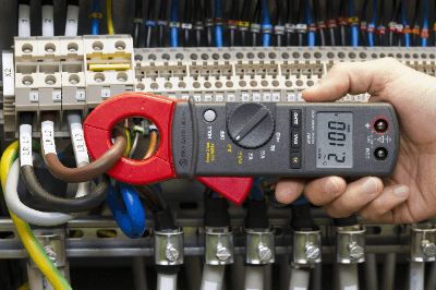
The current waveform is observed by clamping the cable with the head where the current to be measured flows. A clamp meter is an instrument designed to measure the current flowing through a cable without cutting the cable.

The major advantage is that the current can be measured while lighting and equipment are operating as usual, since there is no need to disconnect the cable each time a measurement is made. Like clamp meters, current probes can also observe current waveforms without disconnecting cables.

Uses of Current Probes

Current probes are used to observe current waveforms using an oscilloscope. Applications include current measurement in industrial and electronic equipment. Specifically, there are various applications such as current measurement of inverter equipment, load current of motors, measurement of switching power supplies, and evaluation of LED lighting drive circuits.

Various models are available for high current, low current, and high speed current, depending on the magnitude of the current and the application. There are also current probes for both DC and AC currents, and AC-only current probes that can measure only AC currents.

Principle of Current Probes

Current probes use the magnetic flux generated when current flows through a power cable, so unlike inserting an ammeter, measurement can be made without disconnecting the circuit under test. The head of the current probe (the part that clamps the cable) is made of a high permeability magnetic material (iron-based material such as Permalloy), similar to the core of a transformer, to trap the magnetic flux generated by the cable.

However, the method of magnetic flux detection differs between AC-only current probes and dual-use AC/DC current probes.

1. AC-Only Current Probe

A transformer is capable of converting AC applied to the primary into a voltage or current on the secondary side according to the turn ratio. In a current probe, when a cable carrying AC current is placed in the space enclosed by the core, it acts like the primary winding of a transformer.

The core is wound with a coil that corresponds to the secondary winding, and the value of the current flowing in the cable can be determined from the voltage that appears at both ends of the coil in response to changes in the magnetic flux in the core. This method is mainly used in current probes dedicated to alternating current.

However, since there is no magnetic flux change in direct current, no voltage appears in the secondary winding. Therefore, the above method using the transformer principle cannot be used.

2. Dual-Use AC/DC Current Probe

The AC-DC dual-use type, which can also measure DC current, uses a head with a Hall element embedded inside the core. The Hall element outputs a voltage corresponding to the magnetic flux density due to the Hall effect for both DC and AC, and when this voltage is input to the oscilloscope terminals, the current value (waveform) is drawn on the display.

Other Information About the Current Probe

1. Adjusting the Current Probe

The following two items should be adjusted before using the current probe.

Offset Cancellation
However, a DC offset is unavoidable because a Hall element is used for current detection, and its output is amplified by a DC amplifier and connected to the input terminal of the oscilloscope. Therefore, it is necessary to cancel it for accurate measurement.

The procedure is as follows:

  1. Perform degaussing to eliminate the residual magnetism of the core at the tip of the probe.
  2. Use the offset voltage adjustment function to adjust the oscilloscope display so that it reads 0A.
  3. After this adjustment, attach the current probe to the circuit under test. However, if the measurement is continued for a long time, the DC offset will gradually fluctuate and the 0A position will change, so the above procedure must be repeated from time to time.

Skew Adjustment
When observing current and voltage waveforms simultaneously using current and voltage probes, such as a power measurement in a power circuit, it is necessary to adjust the phase of the signal waveforms, so-called skew adjustment, because the delay time of signals arriving at the oscilloscope body is different for each probe. Adjustment devices, such as power measurement de-skew fixtures, are available and can be used to adjust the phase between probes.

2. What Is Measured With AC Current Probes?

As mentioned above, AC current probes use the transformer principle to detect the current flowing in the circuit under test, but the waveform is observed to be small at low frequency currents. In particular, low-speed pulse signals cause waveform distortion due to sag.

Therefore, when measuring low-frequency signals, including DC, it is important to select a dual-use AC/DC current probe.

3. Frequency Characteristics of Current Probes

The magnitude of current that can be handled by a current probe depends on its frequency, and the higher the frequency, the lower the current that can be measured. This is because the higher the frequency, the more heat is generated in the core and the transformer.

The model of probe to be used should be selected based on the frequency of the current to be measured.

4. Effect of Insertion Impedance

Attaching a current probe to the circuit under test involves inserting a small impedance into the circuit under test. The effect of this impedance on the circuit is so small that it can usually be ignored.

However, if the line through which the current flows is wound around the core multiple times in order to measure a small current, the aforementioned impedance becomes twice as large as the number of times it is wound, thus increasing the likelihood that it will affect the circuit under test.