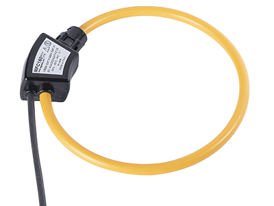
What Is a Current Probe?

A current probe is a probe for measuring current directly on an oscilloscope.
The current waveform is observed by clamping the cable with the head where the current to be measured flows. A clamp meter is an instrument designed to measure the current flowing through a cable without cutting the cable.
The major advantage is that the current can be measured while lighting and equipment are operating as usual, since there is no need to disconnect the cable each time a measurement is made. Like clamp meters, current probes can also observe current waveforms without disconnecting cables.
Uses of Current Probes
Current probes are used to observe current waveforms using an oscilloscope. Applications include current measurement in industrial and electronic equipment. Specifically, there are various applications such as current measurement of inverter equipment, load current of motors, measurement of switching power supplies, and evaluation of LED lighting drive circuits.
Various models are available for high current, low current, and high speed current, depending on the magnitude of the current and the application. There are also current probes for both DC and AC currents, and AC-only current probes that can measure only AC currents.
Principle of Current Probes
Current probes use the magnetic flux generated when current flows through a power cable, so unlike inserting an ammeter, measurement can be made without disconnecting the circuit under test. The head of the current probe (the part that clamps the cable) is made of a high permeability magnetic material (iron-based material such as Permalloy), similar to the core of a transformer, to trap the magnetic flux generated by the cable.
However, the method of magnetic flux detection differs between AC-only current probes and dual-use AC/DC current probes.
1. AC-Only Current Probe
A transformer is capable of converting AC applied to the primary into a voltage or current on the secondary side according to the turn ratio. In a current probe, when a cable carrying AC current is placed in the space enclosed by the core, it acts like the primary winding of a transformer.
The core is wound with a coil that corresponds to the secondary winding, and the value of the current flowing in the cable can be determined from the voltage that appears at both ends of the coil in response to changes in the magnetic flux in the core. This method is mainly used in current probes dedicated to alternating current.
However, since there is no magnetic flux change in direct current, no voltage appears in the secondary winding. Therefore, the above method using the transformer principle cannot be used.
2. Dual-Use AC/DC Current Probe
The AC-DC dual-use type, which can also measure DC current, uses a head with a Hall element embedded inside the core. The Hall element outputs a voltage corresponding to the magnetic flux density due to the Hall effect for both DC and AC, and when this voltage is input to the oscilloscope terminals, the current value (waveform) is drawn on the display.
Other Information About the Current Probe
1. Adjusting the Current Probe
The following two items should be adjusted before using the current probe.
Offset Cancellation
However, a DC offset is unavoidable because a Hall element is used for current detection, and its output is amplified by a DC amplifier and connected to the input terminal of the oscilloscope. Therefore, it is necessary to cancel it for accurate measurement.
The procedure is as follows:
- Perform degaussing to eliminate the residual magnetism of the core at the tip of the probe.
- Use the offset voltage adjustment function to adjust the oscilloscope display so that it reads 0A.
- After this adjustment, attach the current probe to the circuit under test. However, if the measurement is continued for a long time, the DC offset will gradually fluctuate and the 0A position will change, so the above procedure must be repeated from time to time.
Skew Adjustment
When observing current and voltage waveforms simultaneously using current and voltage probes, such as a power measurement in a power circuit, it is necessary to adjust the phase of the signal waveforms, so-called skew adjustment, because the delay time of signals arriving at the oscilloscope body is different for each probe. Adjustment devices, such as power measurement de-skew fixtures, are available and can be used to adjust the phase between probes.
2. What Is Measured With AC Current Probes?
As mentioned above, AC current probes use the transformer principle to detect the current flowing in the circuit under test, but the waveform is observed to be small at low frequency currents. In particular, low-speed pulse signals cause waveform distortion due to sag.
Therefore, when measuring low-frequency signals, including DC, it is important to select a dual-use AC/DC current probe.
3. Frequency Characteristics of Current Probes
The magnitude of current that can be handled by a current probe depends on its frequency, and the higher the frequency, the lower the current that can be measured. This is because the higher the frequency, the more heat is generated in the core and the transformer.
The model of probe to be used should be selected based on the frequency of the current to be measured.
4. Effect of Insertion Impedance
Attaching a current probe to the circuit under test involves inserting a small impedance into the circuit under test. The effect of this impedance on the circuit is so small that it can usually be ignored.
However, if the line through which the current flows is wound around the core multiple times in order to measure a small current, the aforementioned impedance becomes twice as large as the number of times it is wound, thus increasing the likelihood that it will affect the circuit under test.