カテゴリー
category_usa

Power Module

What Is a Power Module?

A power module is a product that integrates power-related circuits into a single module package by combining multiple power semiconductors.

By integrating the necessary functions in an IC (semiconductor integrated circuit) and optimizing the low-power design, power modules are used in a wide range of fields, including industrial equipment used in factories, large white goods, automobiles, railroads, and new energy sources. This technology is used in a wide range of fields, including industrial equipment used in factories, large white goods, automobiles, railways, and new energy.

The market for power modules is still growing rapidly.

Uses of Power Modules

The most familiar application of power modules is the inverters installed in air conditioners, refrigerators, washing machines, and so on. These inverters can control the speed of motors by converting their frequency.

By freely changing the number of motor revolutions, it is possible to reduce wasteful movement and contribute to energy conservation. In contrast, air conditioners without inverters can only turn the motor on and off, which leads to the repetition of extreme movements such as running and stopping the air conditioner, resulting in wasteful power consumption.

Inverters are used to control the speed of motors and are also used in electric vehicles such as HEVs and EVs. It is important that the vehicle’s drive not only turns on and off but also detects and controls the spinning of the tires.

Without this control, the vehicle will slip. In snowy regions, power must be applied to the tires safely and efficiently, and very fine control of motor power is important and indispensable, especially in EVs and HEVs.

Principle of Power Modules

A power module consists of multiple power transistors optimized for its required power supply application, together with a bias drive circuit, and modularized together with peripheral components to improve withstand voltage and switching speed and efficiency during power operation. In addition, the package and substrate are characterized by their heat dissipation and other features that make them easy to use.

Among the power semiconductors widely used in power modules, power transistors have the widest range of applications. The situation is such that technological development is being actively pursued mainly by semiconductor and materials manufacturers. Among power transistors, there are several semiconductor devices listed below.

1. Bipolar Transistor

Bipolar transistors have a simple structure and can handle large amounts of power. However, they have the disadvantages of slow switching speed and high power consumption. In recent years they are no longer the mainstay of power module applications.

2. Power MOSFET

Power MOSFETs (FETs: Field Effect Transistors) have the advantage of the fastest switching speeds and low power consumption. However, they also have the disadvantage of not being able to handle large amounts of power.

3. IGBT

Developed in the 1980s, Insulated Gate Bipolar Transistors (IGBTs) can handle large amounts of power. Compared to MOSFETs, IGBTs are capable of switching that is not too much inferior to MOSFETs. The circuit configuration is a combination of a MOSFET and a BJT (Bipolar Junction Transistor).

Other Information on Power Modules

1. Trends in Next-Generation Power Modules

SiC-MOSFETs have recently been attracting attention as devices for next-generation power modules, because SiC substrates have higher bandgap energy and higher breakdown voltage than Si substrates.

IGBTs can handle high power even with Si substrates, but their bipolar structure makes it difficult to increase the switching speed. SiC-MOSFETs, which are high-power devices with fast switching speed, are currently being considered for next-generation power modules.

The weakness of SiC substrates in mass production has been overcome by the emergence of substrate manufacturers capable of handling 6-inch substrates, which is a result of technological innovation.

2. Power Modules in EVs

The voltage of lithium-ion batteries in EVs is related to the charging time, so we are aiming to shorten the charging time by high-speed charging. To improve the efficiency of the power train, which is equivalent to the engine of an EV, we are working to reduce the current 400V level. In order to improve the efficiency of the powertrain, which corresponds to the engine of an EV, further increase in voltage, from the current 400V to, for example, 800V, is required.

In order to handle high voltage and high controllability of in-vehicle motors, it is important to switch the AC current generated by the inverter circuit at high speed, and power devices and power modules are used here.

カテゴリー
category_usa

Curve Tracers

What Is a Curve Tracer?

A curve tracer is a device that displays the relationship between the voltage applied to a semiconductor device and the current flowing through it.

It is called a curve tracer because it traces a graph (curve) of the voltage-current characteristic and displays it on a display. In semiconductor devices, the relationship between the applied voltage and the flowing current is non-linear and not proportional, like a resistor.

Therefore, measuring the voltage vs. current characteristics of semiconductors and electronic devices requires procedures such as changing the voltage, measuring the current value, and plotting the results on a sheet of paper. With a curve tracer, however, the voltage-current characteristic can be directly displayed on a display.

Uses of Curve Tracers

Curve tracers are used to measure the characteristics of semiconductor devices during development, to inspect devices in manufacturing departments, and to verify the operation of circuits using semiconductors. The main measurement targets are semiconductor devices such as diodes, bipolar transistors, and FETs.

In semiconductors, the voltage applied to the target device is gradually varied and the current flowing at that time is measured. On the other hand, the display of the curve tracer shows the voltage value on the X-axis and the current value on the Y-axis, thus depicting the relationship between the voltage and the current value as a graph.

Optional power supplies are available for high voltage application and high current flow, and the equipment is ready to accommodate a variety of devices.

Principle of Curve Tracers

1. Measurement of Diodes

If the measurement object is a diode, connect a power supply for driving the device between the anode and cathode, set the maximum and minimum applied voltage values Vmax and Vmin, and the power supply will automatically sweep the voltage between them at a frequency of 50Hz to 60Hz. It also measures the current value flowing through the diode at this time.

The horizontal sweep circuit of the CRT uses the voltage of the power supply for driving the semiconductor device as the input signal, while the vertical sweep circuit uses the current flowing through the diode as the input signal, so that the current characteristic (V-I characteristic) against the applied voltage is drawn on the CRT.

2. Transistor Measurement

For bipolar transistor/FET measurements, a current/voltage source using a step generator is connected to the base/gate electrodes. The device drive power supply is connected between the emitter/source and collector/drain, and the maximum and minimum values of the applied voltage, Vmax and Vmin, are set.

For Bipolar Transistors
If the base current is varied stepwise with a step generator and the voltage between emitter and collector and collector current at that time is displayed on the CRT, the static characteristic curve of the transistor is drawn.

In the Case of FET
When the gate voltage is varied stepwise with a step generator, a static characteristic curve of a FET is drawn, showing the relationship between the voltage between source and drain and the drain current.

Curve tracers are designed based on the assumption that a CRT is used for the display. However, since CRTs are rarely produced anymore, the conventional type of curve tracer has disappeared.

Instead, a curve tracer that draws characteristic curves on a display by importing voltage-current characteristic data into a PC is now commercially available.

Structure of a Curve Tracer

A curve tracer consists of a power supply for driving devices, a step generator for controlling transistor base current and FET gate voltage, a CRT and its horizontal sweep and vertical sweep circuits, etc.

Other Information on Curve Tracer

Semiconductor Parameter Analyzer

Curve tracer is a very effective measuring instrument for understanding the basic characteristics of semiconductors, and was a basic measuring instrument utilized in all processes from research and development to product inspection, especially by device manufacturers. They are also used in user acceptance testing of semiconductor devices, and although several Japanese manufacturers used to produce them, all but a few have now withdrawn from the market.

On the other hand, curve tracers, which were developed for solar panel evaluation, are now being sold. In addition, semiconductor parameter analyzers have replaced curve tracers.

These are equipped with multiple voltage and current sources, and the voltage and current are controlled by a controller (PC) to measure the characteristics of semiconductors.

カテゴリー
category_usa

Backplane

What Is a Backplane?

A backplane is a circuit board used in electronic equipment such as computers and telecommunications equipment to connect boards and cards.

It is typically mounted on the back of a device to transmit power and signals to inserted cards and modules. A backplane also consists of brackets for securing boards, sockets for supplying power, and connectors for transmitting signals.

Backplanes are essential to the performance of electronic devices. They support the board, reduce the effects of board vibration and heat, and improve reliability.

Uses of Backplanes

1. Servers and Network Equipment

Backplanes are used in hardware such as servers, network switches, and routers. These devices require many components to process data in parallel at high speed. The backplane efficiently transfers data between these components to maximize system performance.

2. Data Storage System

Backplanes are commonly used in data storage systems to process and store large amounts of data at high speed. These include RAID arrays and storage area networks (SANs).

3. Industrial Computers

Backplanes are also common in computer systems used in manufacturing, energy, transportation, and other industries. Ruggedness and reliability are important in these systems, and backplanes are used to meet these requirements.

4. Test Equipment

Test equipment is used to measure the performance and quality of electronic equipment. Test equipment uses backplanes to connect multiple test cards to accommodate a wide variety of measurement items and conditions.

Principle of Backplanes

To understand the basic workings of a backplane, it is important to understand how it connects hardware components and transfers data.

1. Component Connections

A backplane essentially consists of one or more printed circuit boards. These boards are equipped with slots or ports for connecting the various components of a computer system.

These slots essentially correspond to a specific type of component (e.g., CPU, RAM, hard drive, etc.). Components are physically connected to these slots and communicate with other components through the backplane.

2. Data Transfer

One of the primary functions of a backplane is to allow data transfer between components. This is done through electronic circuits located on the board. Each component uses these circuits to send and receive data.

Depending on the backplane design and component type, data can be transferred in parallel (multiple bits are transferred simultaneously) or in serial (one bit at a time).

3. Plug and Play

Some backplanes offer plug-and-play capability to facilitate the addition or replacement of components. This means that a new component can simply be physically plugged into a slot and the system will automatically recognize its presence and enable it to operate properly.

Together, backplanes allow the components of a system to work together efficiently and share data. Backplanes are critical to the performance and scalability of a computer system.

Types of Backplanes

Backplanes come in a variety of standards and forms.

1. Classification by Standard

Backplane standards include PICMG, ISA, PCI, among others. PICMG is a standard developed by the PCI Industrial Computer Manufacturers Group that supports PCI and PCI Express. ISA (Industry Standard Architecture) is a standard which was adopted for early IBM PCs and other products.

PCI (Peripheral Component Interconnect) is the standard which enables high-speed data transfer.
These standards are sometimes, but not always, compatible. The backplane and the cards or boards to be connected must support the same standard.

2. Classification by Form

There are two forms of backplanes: active and passive. Active backplanes contain chips that buffer signals between slots and can accommodate complex systems.

Passive backplanes do not have any features that drive the circuitry, but have arbitration circuitry on the card or board side. Active backplanes are more likely to fail than passive backplanes.

カテゴリー
category_usa

Switching AC Adapters

What Is a Switching AC Adapter?

Switching AC AdaptersA switching AC adapter is an adapter for converting alternating current (AC) power to direct current (DC) power for information equipment, etc., using the switching method, which is the current mainstream method of AC adapters.

Before the introduction of switching AC adapters, linear AC adapters converted power to low voltage through an iron core (transformer), regulated the AC with diodes, and then used capacitors and other circuits to conduct the electricity to the device being used. On the other hand, unlike the linear method, the switching AC adapter converts AC electricity into high-frequency DC from the start and does not use an iron core (transformer).

The feature of switching AC adapters is that they use switching transistors to perform high-speed voltage conversion, and electricity can flow to the side of the device being used. Since heavy and large transformers are not used, the parts are smaller and lighter, and high power supply efficiency is realized.

Uses of Switching AC Adapters

Switching AC adapters are mainly used in power cables for PCs. Other applications include information communication terminals such as tablets, medical equipment, and audio equipment. Since the power conversion circuit can be separated from the main device, it increases the possibilities of how the device can be used and stored.

And switching AC adapters can be switched on and off without the use of a transformer, making them smaller and lighter. It is also possible to use domestic products overseas, where outlet shapes and power supply/voltage differ by using a converter or transformer.

Since they enable safe, high-precision device operation and are sufficiently resistant to shock and vibration, these days they are being used in a wide range of electronic equipment.

Principle of Switching AC Adapters

Switching AC adapters use a highly efficient switching method, represented by pulse modulation, to convert the desired DC power source in a relatively high-frequency pulse state. This system uses semiconductor devices, such as transistors and MOSFETs, to separate incoming AC voltage into pulses through high-speed switching.

By smoothing the current wave, a flattened DC voltage is obtained. In this process, it is possible to combine power and signals of different frequencies, so it is possible to step down the voltage without a transformer. However, the control method must be carefully considered because of the complexity of the circuitry, and in particular, it is very important to take care of the circuitry of the new switching noise that is generated.

There are several control methods for switching AC adapters, the most typical of which is the “PWN” (pulse width modulation) method. The idea is to stabilize the voltage by adjusting the width of the pulse wave, or the on-time of switching on and off, so that the area of each pulse is the same. Because switching AC adapters can output power without waste by switching power on and off, they are characterized by extremely high power conversion efficiency.

In the case of switching AC adapters, the pulse frequency itself handles higher frequencies than commercial AC frequencies, ranging from several 10 kHz to several 100 kHz. Therefore, they are compact and lightweight, eliminating the need for large, heavy transformers.

How to Choose a Switching AC Adapter

There are many switching AC adapters on the market today. If you make a mistake in selecting the right adapter, you may not only be unable to use your electronic equipment, but in the worst case, you may even damage it.

1. Maximum Rating

The adapter must be capable of delivering the correct voltage (V) and current (A) for the electronic equipment to be used. This is generally found near the input terminals of the electronic equipment or on the rating nameplate. In this case, the voltage should be exactly the same, but the current should be the same or slightly higher.

2. Plug Shape and Polarity

In most cases, the plug part is a pipe-shaped electrode, which provides power by connecting to the contact points of the input terminals of the electronic device, respectively. Since standards have been established to some extent regarding the shape, inner diameter, and polarity of the plug, a compatible plug should be selected for use.

Plugs that convert the outer shape and inner diameter are also available on the market, but the increased number of electrical contacts increases electrical resistance, and this entails the risk of contact failures. It is recommended that plugs with higher voltage and current should not be used.

Other Information on Switching AC Adapters

Switching AC Adapter Using GaN

Compared to the conventional linear method, this switching AC adapter is compact and lightweight because it uses a highly efficient pulse switching method, but it has a certain weight and size for a power conversion adapter for PCs and tablets. Recently, USB-type power adapters using GaN (gallium nitride), a next-generation device, have appeared on the market as even more compact, lightweight, and highly efficient power conversion adapters.

GaN devices have dramatically higher band gap energy and breakdown voltage than conventional Si-based devices, and can operate at higher speeds than SiC (silicon carbide) devices. Therefore, they are suitable for switching operation at higher temperatures and frequencies. The power density per unit area of the transistor can be larger than that of Si-based devices, and the cooling function can be simplified, resulting in smaller, lighter, and more efficient switching AC adapters.

Against this background, manufacturers have recently commercialized more compact portable USB-type switching AC adapters that use GaN devices.

カテゴリー
category_usa

DC Fan Motors

What Is a DC Fan Motor?

DC Fan Motors

DC fan motors are motors that rotate fans and are driven by DC current.

DC fan motors are broadly classified into propeller fans, blowers, cross-flow fans, and other types according to their structure, but they all have the same thing in common: they blow air.

Therefore, it is important to check the catalog specifications and choose the right one for your application and purpose. The most common type of fan motor is a propeller fan, so if you are not sure which one to choose, it is safe to select this one.

Uses of DC Fan Motors

DC fan motors are used to cool the inside of electronic equipment, such as home appliances and office automation equipment, by blowing or convecting air through fan rotation.

When the temperature rises, not only does it cause thermal runaway of electronic equipment, but it is also prone to cause malfunctions. Cooling by DC fan motors is based on air convection, so the most efficient method must be selected in consideration of the structure of the equipment and its temperature.

Principle of DC Fan Motors

The structure of a DC fan motor can be roughly divided into a casing for the structural components, a fan or runner for airflow, and a DC motor for turning the fan or runner.

In the case of a propeller fan, the direction of airflow is the same as the axis of rotation, resulting in a small size, large air volume, and relatively quiet rotation. In contrast, a blower is perpendicular to the axis of rotation, and the outlet of the airflow is narrowed down to concentrate the airflow and obtain high static pressure.

Structure of DC Fan Motors

A typical fan consists of an impeller, casing, main shaft, bearings, and shaft seal.

1. Impeller

The impeller is the part that produces the airflow and is the heart of the fan. There are various types of impellers depending on the application, environment, and other factors related to the efficiency of airflow.

2. Casing

The casing is the part that forms the outer frame of the fan itself and the inner air flow path, and is the part that forms the suction and discharge parts of the fan.

3. Spindle

The central shaft of the fan, which is strong enough to support the impeller.

4. Bearing

The part that receives the rotational motion of the spindle and supports it by smoothing its action. The bearing reduces friction and wear. It is an important part because poor quality can lead to failure due to mechanical wear.

Other Information on DC Fan Motors

1. What Is Airflow Resistance?

When air is blown into a channel, airflow resistance occurs in the opposite direction to the direction in which the air moves in the channel. The more obstacles there are in the flow path that block airflow, the greater the airflow resistance and the lower the airflow. Airflow resistance is energy that increases the static pressure inside the equipment and is also called pressure drop.

In the case of cooling by fan, since airflow resistance is generated, it is necessary to select the performance of the fan in consideration of pressure loss due to the internal structure. Also, considering cooling by a fan, it is important to design the structure so that it does not interfere with airflow.

When multiple fans are used to obtain the required air volume and static pressure, it is also important to consider whether it is most efficient to use them in series or parallel. In general, using fans in parallel increases airflow and using fans in series increases static pressure.

2. Difference From AC Fan Motors

DC fan motors can vary their rotational speed with the motor and circuitry. On the other hand, AC fans have their rotation speed fixed by the frequency of the AC power supply. Currently, DC fans that can freely control the rotation speed are the mainstream, and there are also ACDC fans that rotate DC fans with an AC power supply.

3. What Is a DC Axial Flow Fan?

DC axial fans are DC-driven axial fans. The axial fan has blades mounted in the center of the frame, and air is drawn in from the front of the blades and discharged to the rear.

The direction in which the fan sends air is in the axial direction, which has the advantages of high airflow and low noise. It is widely used for cooling applications for materials that generate heat. Relatively little increase or decrease in airflow due to resistive objects is a characteristic of axial fans.

4. Other Types of Fans

Other types of axial fans include centrifugal fans and oblique flow fans. Centrifugal fans send air not backward but 90 degrees from the direction of suction.

Also, the oblique flow fan is a kind of fan between the axial flow fan and the centrifugal fan. The shape of the blades causes air to be sucked in from the axial direction and pressure is applied in the diagonal direction of the shaft, changing the exhaust direction to send air. It is characterized by its small size and light weight.

Centrifugal fans are suitable when the space of the equipment does not allow air to be blown backward. They are used to draw air from inside densely packed equipment. A typical axial fan motor is a propeller fan. A blade-shaped propeller is placed inside the casing and rotated to generate airflow in the direction of the axis of rotation.

Since the airflow is in the direction of the axis of rotation, it has a compact structure. A typical fan motor in a centrifugal fan is a blower. The centrifugal force of the cylindrically arranged forward-facing blades of a blower creates an air flow in a direction almost perpendicular to the axis of rotation.

カテゴリー
category_usa

AC Fan Motors

What Is an AC Fan Motor?

AC Fan Motors

An AC fan motor is a motor used in a fan that runs on AC power.

There are two types of electricity: DC power and AC power. DC power is a power source in which the direction of the current is always in one direction, while AC power is a power source in which the direction of the current is periodically switched.

DC is direct current and AC is alternate current. AC fan motors are motors that use AC power and whose drive load is a fan.

Uses of AC Fan Motors

AC fan motors are used in a wide range of applications, from consumer products to industrial equipment. The most familiar example is a fan. Some electric fans are equipped with AC fan motors. Most household outlets are AC powered, and AC fan motors are used in fans because of their simple construction.

Industrial applications include fans for local exhaust ventilation. They are used when working underground, in sewage tanks, or in other areas where lack of oxygen is a concern.

Principle of AC Fan Motors

An AC fan motor is an AC motor with a fan (blades) attached to its shaft axis. Eddy currents are generated in the rotor due to changes in the magnetic field generated when current is applied to the stator.

As a result, an induced current is generated by the so-called “Fleming’s right-hand (generator) law. The induced current and the magnetic field generate power by “Fleming’s left-hand (motor) law.

AC fan motors come in two types of AC power sources: single-phase and 3-phase. Therefore, single-phase AC fan motors usually have a built-in capacitor to advance the phase, or a structure called a shaded motor.

The advantage of AC motors is that they are simple in construction, have fewer parts, are more robust, and have a longer service life. The disadvantage is that it is more difficult to adjust the operating speed compared to DC motors.

Since AC motors operate on commercial power, are robust, and easy to maintain, it is expected that they will continue to be widely used in the future, depending on the application.

Other Information on AC Fan Motors

1. Differences Between AC Fan Motors and DC Fan Motors

The difference between AC fan motors and DC fan motors is the power source that drives the fan: AC fan motors operate on AC power, while DC fan motors operate on DC power.

AC fan motors have a constant rotating speed of the fan (blades) depending on the frequency of the AC power supply, while DC fan motors can inexpensively vary their rotating speed through circuitry.

2. What Is an AC Axial Fan?

An AC axial fan is an axial fan driven by an AC fan motor. An axial fan is a fan in which the direction of airflow with the fan is in the axial direction. Wind is generated in the direction perpendicular to the direction of rotation of the blades that generate the wind (axial direction).

As an application, it is often used for cooling machines that generate heat. Relatively little increase or decrease in airflow due to resistive objects is a characteristic of axial fans. In addition to axial fans, there are centrifugal fans and oblique flow fans with different airflow directions.

Centrifugal fans are fans that generate airflow orthogonally to axial fans, causing airflow in the centrifugal direction. A diagonal flow fan is like a fan between an axial flow fan and a centrifugal fan. It draws air in from the axial direction and blows air out in the diagonal direction of the shaft. It is characterized by its small size and light weight.

3. Structure of AC Fan

A typical fan structure consists of an impeller, casing, main shaft, and bearing.

  • Impeller
    The impeller is the part that produces the airflow and is the heart of the fan. It is related to the efficiency of airflow, and there are various types depending on the application, environment, and other factors.
  • Casing
    The casing is the outer frame of the fan itself and the inner airflow path, and is the part that creates the inlet and discharge sections of the fan.
  • Spindle
    The central shaft of the fan, which has the strength to support the impeller.
  • Bearing
    The part that receives the rotational motion of the spindle and supports the spindle while smoothing its action. The bearing reduces friction and wear. It is an important part because the poor quality of this part can lead to failure due to mechanical wear.
カテゴリー
category_usa

Slip Rings

What Is a Slip Ring?

Slip-Rings

A slip ring is a rotating connector that can transmit power or electrical signals from outside the rotating body.

Power and signals are transmitted through a metal ring placed on the rotating body and a brush on the fixed side. It is used to measure the vibration, stress, and axial force of the rotating body and to transmit minute signals for control purposes. They are often used to serve as lead wires that supply power to the rotating body.

There are two main types of slip rings: shaft-end mounted and hollow. The shaft-end type is attached to the end of the rotating element. The hollow type is a ring block that is fitted into the rotating shaft. There are also two types: one in which the ring and brush are integrated, and one in which the ring and brush are separated.

Uses of Slip Rings

Slip rings are available from low-speed rotary applications to 20,000 rpm high-speed applications. Some slip rings can handle high currents of 3,000 A or more, and are widely used in applications ranging from experiments and development to equipment.

They are used to supply power to wind power generators, machine tools, centrifuges, agitators, robot arms, cranes, surveillance cameras, helicopters, turntables, drum heaters, radar antennas, and other rotating body heaters and motors.

They also have a wide range of applications in semiconductor manufacturing equipment, medical equipment such as CT scans, non-destructive testing, and acoustic equipment. They are also used to measure the temperature, strain, and torque of rotating bodies.

Principle of Slip Rings

A ring-shaped electrode part (ring unit) is attached to a rotating shaft, such as a turntable of a rotating body. Brush-shaped electrode parts contact the periphery and sides of the ring unit, and power and signals are transmitted using the points of contact as contact points.

Even if the ring unit rotates, it always has a contact point with the brush, thus enabling stable power supply and signal transmission. The ring unit has bearings to support the brush side.

Precious metals such as copper and silver are used for the contact points between the ring and the brush in the slip ring to stabilize the contact resistance without any risk of leakage. Bronze, silver, and gold are used for the ring, while carbon, copper, and silver alloys are used for the brush portion.

Slip rings are inevitably larger when there are many wires for power or signals. They also wear to a certain degree, so regular maintenance is required.

Other Information on Slip Rings

1. The Role of the Brushes in a Slip Ring

Slip rings transmit and receive from the electrical equipment on the rotating body to the stationary side, with the brushes acting as contacts. Since the brushes are always in contact with the rotating body, the transmission and reception can take place anywhere in a 360° position without wiring kinks or tangles in the shaft.

The number of brushes (contacts) varies according to the number of signals that need to be transmitted and received between the rotating body and the fixed side. Therefore, the more communication devices there are, the more brushes are required, resulting in the overall slip ring becoming huge.

In this case, the number of brushes can be reduced by using serial communication or CAN communication used in automobiles.

2. Disadvantages of Slip Rings

The disadvantage of slip rings is the possibility of contact failure due to brush wear. Since the brushes are in physical contact with the rotating parts, contact failure may occur due to deterioration over time.

Especially in equipment used outdoors, brushes may be damaged prematurely by sand, dust, or water intrusion if they are not protected by a sealed case. Therefore, it is common practice to extend the life of brushes by cleaning and lubricating them once every few years.

The lubricant used at this time should be conductive. Note that if it is not conductive, there is a risk of poor current flow in the brush section, resulting in poor communication between the rotor side and the fixed side.

The life of the brush section is generally from 10 million to 100 million rpm, and up to about 500 million rpm, depending on the manufacturer. When used in long-life equipment, the brush section needs to be maintained periodically.

カテゴリー
category_usa

D-Sub Connectors

What Is a D-Sub Connector?

A D-sub connector is a standardized interface for connecting computers to peripheral devices, named for its “D”-shaped metal shield designed to minimize electromagnetic interference. Available in over 20 varieties, D-sub connectors vary by pin count and size, accommodating a wide range of applications.

Uses of D-Sub Connectors

Once a prevalent standard, D-sub connectors have specific uses based on their pin configurations:

1. 9-Pin D-Sub

Used primarily for RS-232C and RS422 serial communications, the 9-pin variant has historical significance in gaming consoles and computers. It also finds applications in SCSI-3 and Fibre Channel standards.

2. 15-Pin D-Sub

Commonly known as a VGA terminal, the 15-pin D-sub is integral to connecting PC monitors. Despite the rise of digital interfaces like HDMI and DVI, its versatility keeps it in use.

3. 25-Pin D-Sub

This variant supports RS-232C serial interfaces, SCSI for Macintosh, and PC/AT printer connections. While larger than its 9-pin counterpart, it remains relevant for certain devices.

4. 37-Pin D-Sub

The 37-pin D-sub is specialized for professional digital audio and certain SCSI equipment. It’s uncommon in consumer applications but valued in industrial and audiovisual sectors.

Principle of D-Sub Connectors

D-sub connectors feature a housing for electrical contacts, a protective metal hood, and eyelets for securing the connection. They are designed for both plug (male) and socket (female) forms, offering EMI shielding and a variety of screw types for secure attachment.

1. Hood of D-Sub Connector

The metal shell, or hood, serves dual purposes: providing structural integrity and acting as an EMI shield to protect signal integrity.

2. Screw of D-Sub Connector

Secured with screws, D-sub connectors require compatibility between plug and socket screws, available in various lengths and measurement systems.

3. Number of Pins of D-Sub Connector

The pin count, such as the well-known 15-pin DE-15 for VGA connections, dictates the connector’s application, with designs tailored to specific signal assignments.

カテゴリー
category_usa

Current Sensor

What Is a Current Sensor?

A current sensor is a device that measures the current flowing in a circuit.

Current sensors are built into current circuits, so they require the circuit to be disconnected and can be dangerous, but there are also types of current sensors that can measure current by simply clamping a portion of the circuit from the outside.

Uses of Current Sensors

Current sensors are used in situations where the value of the current flowing in a particular circuit is desired. Current sensors that are directly integrated into a circuit are often used to measure and record the value of the current that flows in a circuit on a regular basis. In this case, the information is used for self-maintenance of equipment in operation.

On the other hand, current sensors that clamp the circuit from the outside are useful in non-routine situations, such as pre- and post-checking of energization during electrical work or checking the energized part to investigate the cause when an electrical circuit fails.

Principle of Current Sensors

A current sensor directly connected to a circuit acts as a resistor and measures the actual current flowing through the circuit based on the voltage applied to the circuit. Clamp-type current sensors cannot measure the actual current flowing in a circuit because they are not directly connected to the circuit. Therefore, the magnetic field generated from the current flowing in the wires of the circuit is measured and output as a current equivalent value.

Specifically, there is a magnetic core in the clamping section, and the magnetic field is detected at that section and converted to a current value. Since the polarity of the magnetic field differs between AC and DC, the principle for observation also differs. Among the various measurement methods, the Hall element method is one that can detect both DC and AC.

In this method, a Hall element is incorporated in the magnetic core to measure the magnetic field generated in the circuit under test as a voltage, which is converted into a current value via a built-in amplifier.

How to Select a Current Sensor

There are two types of current sensors: direct-current circuits and alternating-current circuits. It is important to select an appropriate current sensor depending on the current component of the circuit you wish to measure and the accuracy you wish to measure.

Generally, if you do not require a large degree of accuracy, select a Hall element type that can handle both DC and AC circuits, but it may not clamp well depending on the installation position of the circuit.

For AC, select a Rogowski type current sensor without a core, which allows measurement while bending the clamping section.

Other Information on Current Sensors

1. Detection Method of Current Sensors

Current sensors have different applications depending on the characteristics of the detection method. Current detection methods can be broadly classified into two types: resistance detection type and magnetic field detection type.

Resistance Detection Type
The resistance detection type detects current by inserting a resistance called a shunt resistor at the point where the current to be measured flows. According to Ohm’s law, a voltage drop occurs when a current flows through the resistor.

By measuring this voltage value and dividing it by the resistance value, the current can be measured. Although it depends on the circuit design, it is common to select a small resistance value for the shunt resistor so that it does not affect the operation on the circuit.

However, when measuring large currents, heat generation and withstand voltage of the resistor value can be a problem. If the voltage drop is small, a current sense amplifier should be used to amplify the voltage to be detected.

Magnetic Field Detection Type
The magnetic field detection type measures the magnetic field created by the flowing current. According to Ampere’s law, when a current flows, a magnetic field is generated in the direction in which the right-hand thread turns when the direction of the current is the direction in which the right-hand thread moves.

This magnetic field is detected using a Hall element. A Hall element is an element that uses the Hall effect, a phenomenon in which an electromotive force appears in a direction orthogonal to both the current and the magnetic field, and is used to detect the magnetic field.

2. Circuit of a Current Sensor

The resistance detection type using a shunt resistor is used for overcurrent detection in power supplies such as DC/DC converters, LED drivers that are driven by current, and current control and circuit protection in motor drive circuits. The magnetic field detection type using Hall elements does not require an element to be placed on the circuit pattern where the current is to be measured, so it is also used in clamp ammeters that clamp wires to measure current and in motor position detection.

Current detection using resistance detection type with a shunt resistor or magnetic field detection type with a Hall element often produces a small output, so when a circuit is configured with discrete components, it is common to combine a current sense amplifier or operational amplifier in the circuit. Manufacturers also offer dedicated ICs with built-in amplifiers instead of discrete components, which can be selected according to the application and characteristics.

カテゴリー
category_usa

Thermostat

What Is a Thermostat?

Thermostats
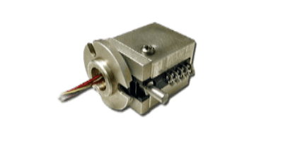
A thermostat is a device used in temperature control.

It is responsible for controlling the operating signals for cooling and heating devices based on the results of temperature detection. The general function of a thermostat is to detect temperature, but some products may also have a function to detect abnormal temperature increases and prevent temperature overshoots.

Usage of Thermostats

Thermostats are commonly used to control either the upper or lower limit of a temperature setting, such as a temperature heater for a water tank.

Other types of thermostats are also available, such as those that control both the upper and lower limits and specify a certain temperature range, as in precision air conditioning, or those that not only control the upper and lower limits of the set temperature but also prevent the temperature from rising to an abnormal level or detect a specified temperature.

In addition to those incorporated into electrical circuits as described above, some are directly incorporated as open/close valves in fluid circuits, such as engine room cooling water flow rate control. In any case, the advantage of thermostats over other types of temperature detectors is that they can be made smaller.

Principle of Thermostats

Among thermostats, the bimetal thermostat uses the phenomenon of metal expanding and contracting due to heat. Since the coefficients of thermal expansion between different metals are different in bimetals, the entire bimetal is curved toward the metal with the relatively smaller coefficient of thermal expansion due to the difference in the magnitude of expansion and contraction caused by temperature changes.

By utilizing this curvature of the bimetal, it is possible to create a circuit in which the contacts open and close in response to temperature. By setting an arbitrary threshold for the opening and closing of the contacts, it is possible to control the circuit such that the power supply of the heat source or cooling source is switched on and off after a certain temperature.

Another advantage of this mechanism is that the element can be miniaturized because it directly utilizes the temperature sensitivity of the bimetal material, rather than actually measuring the temperature and then controlling it electrically. If the thermostat is incorporated into a fluid circuit as an open/close valve, rather than as a contact point in a circuit, it can represent a control valve that opens gradually in response to temperature changes.

Types of Thermostats

Thermostats are devices used to control temperature, and various types of thermostats are used depending on the application.

1. Electronic Thermostats

Electronic thermostats control temperature by computer control rather than by motion signals. This allows for more accurate temperature control in the operating environment.

Temperature control can also be performed automatically, enabling appropriate temperature control and cost reductions in electricity and other expenses. It is mainly used in the industrial field, where it is widely used to control the cooling water temperature of engines and the temperature inside vinyl greenhouses for agriculture.

2. Bimetal Thermostat

Bimetal thermostats consist of two types of metals with different thermal expansion coefficients. When the temperature rises to the set temperature, the contact points composed of the two types of metals separate and the circuit can be interrupted.

A thermostat that uses this principle is called a bimetal thermostat. Bimetal thermostats are used in refrigerators and gas water heaters used in homes.

They are used in many industrial products because of their simple structure and ability to control temperature accurately. Also, its metal construction makes it resistant to breakage even after long-term use.

3. Liquid Expansion Thermostats

Liquid expansion thermostats have a structure in which a liquid with a high thermal expansion coefficient is sealed inside a metal tube. The expansion of the enclosed liquid causes the contact points to operate to control the temperature.

When metal is used as the liquid, the accuracy of temperature measurement is higher. For this reason, the thermocouple is widely used in cooking utensils and refrigeration equipment that require precise temperature measurement.

Another feature of liquid expansion thermostats is that their electrical capacity can be increased. By increasing the electrical capacity, a wider range of temperatures can be detected. For this reason, liquid expansion thermostats are widely used in industrial fields such as large-scale factories that require temperature detection over a wide range.