カテゴリー
category_es

Transformadores de Alta Tensión

¿Qué es un Transformador de Alta Tensión?
Transformadores de Alta Tensión

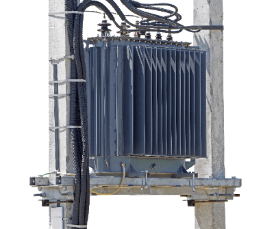
Un transformador de alta tensión es un dispositivo que tiene la capacidad de transformar una tensión de entrada elevada en una tensión de salida reducida o aumentada.

El transformador, también conocido como transformador eléctrico, es un dispositivo diseñado para cambiar la tensión de una corriente eléctrica de entrada y convertirla en una tensión de salida diferente. Cuando la tensión de salida es menor que la de entrada, se dice que el transformador actúa como reductor de tensión. Por otro lado, cuando la tensión de salida es mayor que la de entrada, el transformador se denomina elevador de tensión. Las tensiones de alimentación se dividen en categorías, como baja tensión, alta tensión y alta tensión especial. La alta tensión se refiere a tensiones de corriente alterna (CA) que oscilan entre 600 V y 7 kV.

Usos de los Transformadores de Alta Tensión

Por lo general, los transformadores de alta tensión se utilizan para suministrar energía a grandes instalaciones con un elevado consumo eléctrico, como fábricas, hospitales e instalaciones comerciales.

La electricidad generada en las centrales eléctricas es de muy alta tensión, con tensiones de decenas de miles de voltios. No puede utilizarse si se transmite directamente al usuario. Sin embargo, desde el punto de vista de la eficacia de la transmisión, la energía se transmite a alta tensión y baja corriente en las proximidades de la fuente de suministro, y luego se reduce a una tensión que pueda ser utilizada por un transformador.

Los transformadores de alta tensión suelen estar integrados en instalaciones receptoras de energía de alta tensión denominadas celdas y se sitúan en los tejados.

Principio de los Transformadores de Alta Tensión

Un transformador consta de dos bobinas. Las dos bobinas están separadas eléctricamente pero conectadas magnéticamente por un núcleo de hierro.

La bobina del lado de entrada es la bobina primaria y la del lado de salida es la bobina secundaria. Cuando circula corriente por la bobina primaria, se genera un flujo magnético según la ley de Ampere. Este flujo magnético se transmite a través del núcleo de hierro a la bobina secundaria, donde se genera una tensión en función del número de espiras de la bobina según la ley de Faraday de inducción electromagnética. Así, utilizando la bobina y el núcleo de hierro, se puede convertir la tensión entre la fuente de alimentación de entrada y la de salida.

Más Información sobre los Transformadores de Alta Tensión

1. Sistema de Refrigeración de los Transformadores de Alta Tensión

Dado que en el interior del transformador se genera calor como consecuencia de las pérdidas de potencia, se introduce un sistema de refrigeración. Existen dos métodos de refrigeración: el método lleno de aceite, en el que los devanados se refrigeran con aceite aislante, y el método moldeado, en el que no se utiliza aceite.

Los transformadores de alta tensión se utilizan en instalaciones en las que se requieren medidas estrictas de prevención de catástrofes, por lo que se suele emplear el “método moldeado”, ya que presenta un menor riesgo de incendio. En el caso de los transformadores rellenos de aceite, se utiliza petróleo de clase 3 como aceite aislante. Tenga en cuenta que a medida que aumenta la capacidad de los transformadores de alta tensión y la cantidad de aceite supera los 400 litros, el aceite por sí solo está regulado por la Ley de Servicios contra Incendios como sustancia peligrosa.

A medida que aumenta la capacidad, resulta más difícil utilizar transformadores autorrefrigerantes, por lo que se utilizan sistemas de circulación forzada.

2. Precio de los Transformadores de Alta Tensión

Los transformadores de alta tensión son relativamente baratos entre los equipos industriales debido a su sencillo mecanismo. Para los transformadores con una tensión temporal general de 6.600 V/3.300 V y una tensión secundaria de 400 V/200 V/105 V, existen productos de catálogo de diversas empresas de electricidad pesada.

Se considera que los productos de catálogo tienen un límite superior de unos 2.000 kVA, por encima del cual se fabrican por encargo. Los transformadores autorrefrigerantes rellenos de aceite se consideran costosos, con precios que varían desde cantidades significativas para los de varias decenas de kVA, hasta montos considerablemente más altos para los de 2.000 kVA (a partir de 2021). Los sistemas moldeados se encuentran en una categoría aún más cara en comparación.

Los precios anteriores corresponden a transformadores reductores generales, pero como las especificaciones especiales se hacen por encargo, es necesario consultar los precios con las empresas de maquinaria eléctrica pesada.

3. Capacidad de los Transformadores de Alta Tensión

La capacidad de un transformador de alta tensión viene determinada por el valor de corriente admisible de los devanados y la capacidad del núcleo de hierro magnético. Si por los devanados circula una corriente superior al valor admisible, el transformador se protege mediante un relé de sobreintensidad, ya que esto puede provocar la rotura del transformador.

La capacidad de un motor trifásico, por ejemplo, se mide en kW (kilovatios), mientras que la capacidad de un transformador de alta tensión se mide en kVA (kVA). Los productos de catálogo para transformadores de alta tensión monofásicos de tres hilos tienen un límite superior en torno a 300 kVA, mientras que los transformadores trifásicos de 400 V/200 V tienen un límite superior de 2.000 kVA.

Si se utiliza un tipo de cubículo, el límite superior para los productos comerciales es de unos 750 kVA debido al tamaño del recinto y a la capacidad de refrigeración.

4. Factor de Potencia de los Transformadores de Alta Tensión

Es importante tener en cuenta que la capacidad de trabajo de un transformador de alta tensión está influenciada por el factor de potencia de la carga. Cuanto más alejado esté el factor de potencia de 1, menor será la capacidad de trabajo disponible. Para utilizar el transformador de alta tensión a su máxima capacidad sin desperdicio, se recomienda mantener el factor de potencia en el secundario del transformador en 1.

En el caso de maquinaria industrial con múltiples motores, es común que el factor de potencia tienda a ser retardado. Para compensar esto, se suelen utilizar condensadores de potencia conectados en paralelo a la carga como medida general.

Los transformadores de alta tensión están diseñados para lograr una eficiencia óptima con cargas alrededor del 60%. Por lo tanto, es importante seleccionar un condensador con suficiente margen para que la capacidad utilizada se encuentre normalmente en torno al 60%.
カテゴリー
category_es

Máquinas de Ensayos de Vibraciones

¿Qué es una Máquina de Ensayos de Vibraciones?

Una máquina de ensayo de vibraciones es un dispositivo utilizado para aplicar vibraciones a componentes o productos con el fin de evaluar su resistencia y características de respuesta ante las vibraciones.

Estas máquinas se utilizan para verificar posibles daños o fallas causadas por las vibraciones, así como para examinar las características de respuesta de los componentes. Las vibraciones pueden generar fatiga en un producto a lo largo del tiempo, por lo que las máquinas de ensayo de vibraciones son empleadas para garantizar su calidad.

El objetivo principal de estas máquinas es evaluar la resistencia a vibraciones de un producto mediante la aplicación de vibraciones sinusoidales o aleatorias. También se utilizan para medir la impedancia mecánica, que representa la respuesta de un sistema mecánico a las vibraciones, determinar frecuencias de resonancia y aplicar contramedidas de vibración.

Usos de las Máquinas de Ensayos de Vibraciones

Las máquinas de ensayo de vibraciones se utilizan para diferentes propósitos, entre ellos:

  • Evaluación de la resistencia a las vibraciones de componentes y productos, así como el rendimiento demostrado en entornos vibracionales. Por ejemplo, se comprueba si piezas de automóviles y componentes electrónicos pueden soportar las vibraciones y mantener su funcionamiento adecuado.

  • Comprobación de los efectos de las vibraciones en productos y sus embalajes durante el transporte. Esto es relevante para productos enviados, como electrodomésticos, equipos de oficina y alimentos.

  • Evaluación de la resistencia de materiales de construcción y estructuras ante terremotos, incluyendo la eficacia de estructuras de aislamiento sísmico y control de vibraciones.

  • Análisis de las características de vibración de álabes de turbinas y vibraciones de torsión en ejes de generadores de turbinas.

  • Medición de la impedancia mecánica en bastidores de máquinas herramienta.

  • Calibración de medidores de vibraciones y sismómetros, entre otros instrumentos.

Principio de las Máquinas de Ensayos de Vibraciones

Las máquinas de ensayos de vibraciones, también conocidas como comprobadores de vibraciones, se clasifican según su sistema de accionamiento en mecánicos, hidráulicos, electrodinámicos y servomotores, cada uno con un principio de funcionamiento distinto.

1. Máquinas de Ensayos de Vibraciones Mecánicas

Este sistema utiliza un motor como fuente de energía para convertir el movimiento de rotación en un movimiento alternativo. Aunque son más económicas que los sistemas hidráulicos y electrodinámicos, las máquinas de vibración mecánicas han sido reemplazadas en los últimos años debido a sus limitaciones en términos de controlabilidad.

2. Máquinas de Ensayos de Vibraciones Hidráulicas

Este sistema emplea la presión hidráulica de una bomba para generar vibraciones. Una válvula de control regula el flujo de líquido para producir el movimiento vibratorio. Es especialmente adecuado cuando se requiere baja frecuencia, desplazamientos largos y alta potencia. Se utilizan comúnmente para vibrar estructuras de gran tamaño, como edificios, sometidas a ondas sísmicas. La frecuencia de vibración oscila entre 1 y 300 Hz.

3. Máquinas de Ensayos de Vibraciones Electrocinéticas

Este método se basa en la fuerza de Lorentz que se genera cuando se aplica corriente eléctrica a un conductor en un campo magnético. Al pasar una corriente alterna por una bobina de accionamiento ubicada en un campo magnético, se genera un movimiento alternativo en respuesta a la corriente. La vibración del excitador es detectada por un sensor y transmitida al controlador, que mantiene la vibración en un valor predeterminado. Una característica distintiva de este método es su amplio rango de frecuencias de vibración, que puede llegar a frecuencias especialmente altas. La gama típica de frecuencias de vibración es de 5 a 3,000 Hz, aunque algunos excitadores más pequeños pueden alcanzar frecuencias más altas, de hasta 40,000 Hz.

4. Máquinas de Ensayos de Vibraciones Servomotores

Este método de ensayo de vibraciones utiliza un actuador lineal con servomotor, que combina un servomotor de corriente alterna con un husillo de bolas. La capacidad de carga de este tipo es inferior a la de los sistemas hidráulicos, y su rango de frecuencias es inferior al de los sistemas electrodinámicos. El rango de funcionamiento se encuentra entre los sistemas hidráulicos y electrodinámicos, con una frecuencia que varía desde 0.01 hasta 300 Hz.

Más Información sobre las Máquinas de Ensayos de Vibraciones

1. Tipos de Pruebas de Vibración

Existen diferentes tipos de pruebas de vibración que se utilizan en las máquinas de ensayos de vibraciones:

Prueba de Vibración Sinusoidal
En esta prueba, la vibración se repite en un período fijo. Hay dos métodos comunes: uno en el que la frecuencia y la amplitud de vibración se mantienen constantes, y otro en el que se varía la frecuencia mientras se ajusta la amplitud de acuerdo con la frecuencia de vibración. Esta prueba se utiliza principalmente para evaluar la resistencia a las vibraciones y también se puede emplear para comprobar la resonancia, la frecuencia de resonancia y las características de respuesta a la vibración de la muestra.

Prueba de Vibración de Onda Aleatoria
En esta prueba, la muestra se somete a una forma de onda de vibración aleatoria sin patrón fijo. Las condiciones de la prueba se especifican en términos de ancho de banda de frecuencia y densidad espectral de aceleración. Se realiza en tres direcciones: arriba, abajo, izquierda, derecha y atrás. Esta prueba proporciona una buena simulación de cómo los productos eléctricos y componentes electrónicos se comportan bajo las cargas de vibración en aplicaciones de transporte terrestre y aeroespacial. Es especialmente efectiva para detectar degradación del rendimiento y fallos mecánicos debido a la acumulación de tensiones, y ofrece resultados de ensayos más representativos del entorno real de uso.

Pruebas de Choque
Estas pruebas consisten en aplicar un impacto pulsante en forma de onda con una aceleración máxima y una duración de acción especificadas a la muestra. Estas pruebas evalúan la resistencia y las características de la muestra frente a situaciones de impacto y choque.

2.Tendencia hacia Máquinas de Ensayos de Vibraciones más Grandes y más Pequeñas

Por un lado, hay una tendencia hacia el desarrollo de máquinas de ensayos de vibraciones cada vez más grandes. Si bien en el pasado los productos eléctricos, componentes electrónicos y piezas de automoción han sido los principales objetos de ensayo, ahora se requieren equipos de ensayo más grandes para aplicaciones como embalajes de carga, piezas para vehículos ferroviarios, industria aeroespacial y construcción antisísmica. Además, la industria aeroespacial exige frecuencias de vibración más altas en comparación con los productos de consumo y automoción, lo que ha impulsado el desarrollo de equipos de ensayo que cumplan con estas especificaciones.

Por otro lado, también existe una creciente demanda de máquinas de ensayos de vibraciones más pequeñas. Un ejemplo son los comprobadores de vibraciones de sobremesa, que se utilizan para detectar fallos de soldadura en placas de circuito impreso, problemas de contacto en conectores y apriete inadecuado de tornillos y tuercas, entre otros. Además, se han desarrollado comprobadores de vibraciones portátiles que se utilizan para evaluar la resistencia a las vibraciones de equipos electrónicos y medir las características de respuesta a las vibraciones de puntos específicos.

カテゴリー
category_es

Voltage Generators

What Is a Voltage Generator?

Voltage Generators

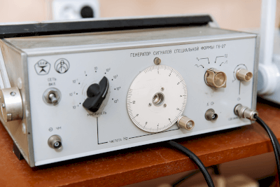
A voltage generator is a generator that generates arbitrary voltages with high precision and output them as needed for various applications.

A common use for voltage generators is to produce specific voltages during the testing phase in research and development.

There are various types of voltage generators available from manufacturers of measuring instruments, and it is important to select the appropriate one based on the operating environment and intended use.

The demand for voltage generators in the field of in-vehicle component development, especially in relation to CASE (Connected, Autonomous, Shared, Electric) compliance, is growing.

Applications of Voltage Generators

Voltage generators are used to extract specific voltages for tests in the development of electronic components for xEVs (extended-range electric vehicles) in support of CASE initiatives.

Currently, voltage generators can be broadly categorized into four types, and it is necessary to choose the type that best fits the purpose and operating environment.

The classifications of voltage generators are as follows:

  • Bipolar output: Outputs across positive polarity without switching.
  • Four-quadrant output (source and sink operation).
  • Linear bipolar output: For AC-DC conversion, outputs across both positive and negative polarity with switching.
  • 2-quadrant output (source and sink operation).

Principles of Voltage Generators

Voltage generators consist of a complex assembly of coils, resonance mechanisms, and control boards. They can generate any desired voltage according to the specified function of the generator.

These generators are capable of high-output and high-voltage analog waveform control with dynamic characteristics. They can operate under positive and negative pole source/sink and bipolar outputs capable of 4-quadrant operation.

Voltage generators play an essential role in the development of CASE-compliant electronic components for xEVs.

Advancements in boost/breakdown technology using materials that combine rare metals are simplifying and downsizing amplification circuits. This technology is expected to have wider applications in the future.

The advantages and disadvantages of voltage generators are as follows:

  • Advantage: High-precision, high-quality arbitrary voltage extraction is possible.
  • Demerit: Special high-voltage level voltage generation requires considerably large equipment.
カテゴリー
category_es

Electromagnetic Flow Meters

What Is an Electromagnetic Flow Meter?

Electromagnetic Flow Meters

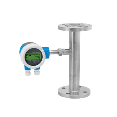
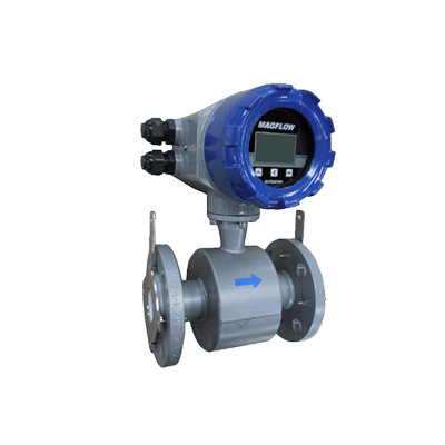
Electromagnetic flow meter is a device that utilizes the principles of electromagnetic induction to measure fluid flow rates.

Electromagnetic flow meters are characterized by the absence of moving parts and the absence of pressure drop in the measurement process. However, due to their operating principle, electromagnetic flow meters are limited to measuring conductive liquids and cannot measure insulating fluids like oils or gases.

When used with conductive liquids, these meters offer precise measurements unaffected by factors such as temperature, pressure, liquid density, viscosity, or conductivity. They are also capable of measuring the flow rates of slurries and corrosive chemicals containing suspended particles.

Applications of Electromagnetic Flow Meters

Electromagnetic flow meters find applications in various industries due to their ability to measure flow rates in challenging conditions. Some of the common applications include:

  • Fluids containing solids, such as sand-water mixtures in civil engineering projects
  • High-viscosity fluids like cement milk and mortar
  • Acidic liquids, including sulfuric acid and hydrochloric acid, in chemical plants
  • Basic liquids such as caustic soda used in scrubbers
  • Pulp liquids and bleaching agents in the paper industry
  • Beverages like fruit juice and wine in the food industry
  • Pharmaceuticals and blood plasma in the medical industry

As mentioned, electromagnetic flowmeters are versatile instruments used across a wide range of fields.

Principles of Electromagnetic Flow Meters

Electromagnetic flow meters operate based on Faraday’s Law of Electromagnetic Induction, which involves the generation of voltage in a conductor moving through a magnetic field.

This phenomenon occurs when a conductive object moves within a magnetic field, generating a voltage proportional to its speed. Electromagnetic flow meters convert this voltage into flow rate data by detecting it.

A typical electromagnetic flowmeter consists of a measuring tube through which the liquid flows, an exciting coil that generates a magnetic field, and a circuit that measures the voltage induced by electromagnetic induction.

When a magnetic field is created perpendicular to the measuring tube, the conductive liquid flowing through the tube intersects the magnetic field perpendicularly, resulting in the generation of a voltage perpendicular to both the measuring tube and the magnetic field. This voltage can be used to determine the liquid flow rate.

How to Select Electromagnetic Flow Meters

The choice of an electromagnetic flow meter depends on the properties of the fluid to be measured and the installation conditions. Here are some key considerations:

1. Separate Type or Integrated Type

Select between a detector/transducer integrated type or a separate type based on the installation location.

2. Measuring Tube

Choose the measuring tube material that matches the type of liquid to be measured. Options typically include rubber and PFA lining materials.

3. Connection Method

Select the appropriate piping connection method, such as wafer or flange, based on ease of installation and removal. Note that ceramic measuring tubes are typically compatible only with wafer connections.

Additionally, choose the bore size of the measuring tube to match the connecting piping.

4. Electrode and Ground Ring Materials

Select electrode and grounding ring materials that are compatible with the fluid being measured to prevent corrosion. Materials like SUS316L are commonly used for general applications, while other materials like hastelloy, tantalum, or platinum iridium may be suitable for specific corrosive fluids.

5. Communication Method

Determine the communication method for the electromagnetic flow meter. Options may include 4-20 mA DC current analog transmission, HART communication, or other proprietary communication methods. Choose the method that aligns with your maintenance and data collection requirements.

カテゴリー
category_es

Power Loggers

What Is a Power Logger?

A power logger is a device designed to measure and record electric power consumption. Power loggers are offered as products by manufacturers of measurement instruments and are equipped with memory to store power data while simultaneously displaying it.

The unit of electric power measurement is typically in kW (kilowatts) or W (watts), and this information is displayed on the device’s interface panel.

Some power loggers provide the option to choose different sampling rates, with some offering high sampling rates, such as up to 100 times per second (100 Hz).

A variety of power logger models are available, and the appropriate instrument should be selected based on the required measurement accuracy.

Uses of Power Loggers

Power loggers are primarily used for the measurement of electric power consumption. Most power loggers are compact and portable, making them convenient for field use in various applications.

Specific examples of their usage include:

  • Verifying proper operation during electrical work trials
  • Maintenance of production equipment
  • Temporary power measurement for industrial machinery management
  • Monitoring power consumption of household electronic equipment
  • Measurement of power in lithium-ion battery packs
  • Battery management systems in electric vehicles

Principles of Power Loggers

Power loggers can be broadly categorized into two types: direct power measurement devices and indirect power measurement devices.

Both types are equipped with an interface panel for real-time data monitoring, displaying power values, typically in kW (kilowatt) or W (watt). In some cases, mW (milliwatt) units are used for precision measurements. Users can configure parameters such as sampling rates and recording formats on this panel. Higher sampling rates allow for finer data resolution, but they may limit the duration of data storage.

Recording media, such as USB flash memory or SD cards, are commonly used. Data is often stored in CSV or TXT file formats. Since analog signals are used for input data, measurement accuracy can be affected by noise. It is essential to implement noise-reduction measures, such as shielding, to enhance measurement precision.

1. Direct Power Measurement Devices

Direct power measurement devices come with a clamp meter for measuring current and an alligator clip cable for measuring voltage. They measure and record power based on current and voltage readings. In the case of a 3-phase power supply, two clamp meters and three alligator cables are used.

For single-phase power measurement, one clamp meter and two alligator cables are typically employed. Most direct power measurement devices can simultaneously record voltage and current along with power data. Some devices can also measure reactive power and power factor simultaneously.

When using direct power measurement devices, the maximum measurable voltage is determined by the device’s specifications. It is essential to confirm this limitation before making a purchase. If measuring high-voltage power is required, it may be necessary to use an instrument transformer to step down the voltage and then multiply the measurement result by the transformer ratio.

2. Indirect Power Measurement Devices

Indirect power measurement devices record power signals that have been converted by power transducers or similar devices. Typically, the input signal is an analog signal, such as 0-5 VDC or 4-20 mA DC. The maximum measurable value is determined by the range of the power transducer.

カテゴリー
category_es

Conductive Sheets

What Is a Conductive Sheet?

A conductive sheet is a thin product made of an electrically conductive material.

Conductive sheets are flexible, thin, and lightweight, adapting to various shapes and curved surfaces. Their conductive properties enable the transmission and connection of electrical signals.

Additionally, conductive sheets may shield against electromagnetic waves, reducing surrounding electromagnetic influences and maintaining signal stability in electronic equipment.

Uses of Conductive Sheets

Conductive sheets have diverse applications, as detailed below:

1. Semiconductor Products

Conductive sheets are integral to semiconductor products, such as touch panel technology, where they detect finger and pen input. They also support LCD backlighting, providing electrical supply and wiring for light-emitting diodes (LEDs).

2. Manufacturing Facilities

In clean rooms of manufacturing plants for electronic substrates and semiconductors, conductive sheets prevent static electricity from damaging semiconductor devices.

3. Research and Development

Widely used in electronics R&D, conductive sheets are crucial in developing new devices, sensors, and flexible electronic devices.

Principle of Conductive Sheets

Conductive sheets feature a structure with uniformly dispersed conductive materials like microscopic particles or fibers, enabling free electron propagation. Common materials include metals like silver and copper, carbon nanotubes, and conductive inks. Some are made from antistatic resin or rubber sheets coated with conductive powder.

For base sheets made of cloth, conductive threads are woven into the fabric. Some products, to maintain flexibility, are laminated with flexible sheets.

Cleaning conductive sheets with detergent can restore their efficacy by removing dust and lowering surface resistance.

Types of Conductive Sheets

Conductive sheets vary in type, as outlined below:

1. Metal Conductive Sheet

Metal conductive sheets, mainly copper and aluminum, connect electrical circuits and contacts. These sheets are durable and withstand high temperatures.

2. Carbon Conductive Sheet

Carbon conductive sheets, made from carbon nanotubes and graphite, are flexible, making them ideal for flexible electronic devices and touch panels.

3. Conductive Ink Conductive Sheet

Conductive ink sheets are created by dispersing conductive particles or polymers in an ink medium. They are used for printing patterned conductive patterns or contacts.

4. Fiber Conductive Sheet

Fiber conductive sheets use metallic or carbon fibers. Their flexibility allows integration into wearable and smart textile products, offering both comfort and conductivity.

カテゴリー
category_es

Internal Grinders

What Is an Internal Grinder?

Internal Grinders

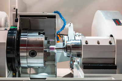
An internal grinder is a machine designed to grind the internal surfaces of primarily cylindrical workpieces.

Grinding is a machining process that utilizes grinding wheels.

Grinding wheels consist of tough abrasive grains, such as aluminum oxide and silicon carbide, bonded together with a bonding agent.

Grinding is not suitable for rough machining due to the shallow depth of cut compared to cutting processes.

However, it is highly effective for precision machining, delivering excellent dimensional accuracy and surface finish roughness.

Uses of Internal Grinders

Internal grinders employ a small-diameter internal grinding wheel attached to a spindle referred to as a wheelhead.

The workpiece is secured using an external jaw chuck or an electromagnetic chuck attached to the spindle.

Internal grinders are broadly categorized into two types based on the grinding method: rotary workpiece type and planetary type.

In the workpiece rotary type, the wheel spindle and the main axis rotate relative to each other, while the grinding wheel on the wheel spindle oscillates back and forth as it cuts into the workpiece mounted on the main axis.

The planetary grinding method is employed when the workpiece is large or challenging to balance during rotation.

While rotating the wheel spindle, the spindle itself is given a planetary motion to grind along the internal surface.

To maintain the sharpness, accuracy, and shape of the grinding wheel, dressing is necessary when changing the wheel or after each grinding cycle.

Grinding wheel dressing involves placing the rotating grinding wheel on the diamond dresser installed on the machine.

Principles of Internal Grinders

In basic workpiece-turned internal grinders, the wheel head with the grinding wheel attached has a sliding mechanism relative to the spindle, allowing the grinding wheel to enter the hole.

Internal grinders are used to grind the internal surface of cylindrical shapes, but by adjusting the slide position, they can also grind the end face perpendicular to the shaft center of the hole.

Simultaneous grinding in a single process enables high-precision machining.

The hole’s diameter and length that can be ground depend on the grinding wheel’s outside diameter and the machine’s stroke.

Various bore diameters can be accommodated by selecting a grinding wheel that matches the bore diameter.

However, as bore deflection tends to be higher due to the wheel spindle’s small size, it is advisable to choose a grinding wheel with the largest possible diameter for the bore and mount it on the wheel spindle head using a short-shafted wheel spindle.

The machine can also handle stepped bore diameters, and coaxiality of the bore diameter can be achieved in a single process, ensuring high precision. Taper grinding can also be performed by angling the spindle.

When grinding workpieces with a grinding wheel, a low peripheral speed can cause abrasive grains to detach along with the bonding agent.

Typically, the wheel spindle head rotates at 2000 to 3000 rpm under standard grinding conditions to achieve the desired peripheral velocity due to the grinding wheel’s small diameter.

The spindle workpiece speed is set to maintain a peripheral speed of about 35 to 45 m/min for the grinding surface.

カテゴリー
category_es

Thermal Flow Meters

What Is a Thermal Flow Meter?

Thermal Flow Meters

A thermal flow meter is a type of flowmeter that measures the flow rate by using the thermal conduction characteristics of the fluid passing through it.

This device measures flow rate by detecting the temperature difference between the upstream and downstream of the fluid, making it particularly suitable for gas flow measurement. Although there are models for liquid flow measurement, they are typically limited to measuring small flow rates.

Thermal flow meters are sensitive to contamination, hence they are best used for measuring pure gases. They are known for their accuracy in flow rate measurement and can be applied to viscous fluids and high-temperature fluids. However, accurate measurement requires calibration and compensation due to the fluid’s thermal conductivity characteristics and temperature fluctuations. Some fluids may also exhibit slow temperature changes, affecting the response time of the meter.

Flowmeters can be categorized into two types: those measuring volume and those measuring mass. Most measure volumetric flow, but thermal flow meters are capable of measuring mass flow, which is more accurate for gases as their volume changes with temperature and pressure.

Uses of Thermal Flow Meters

Thermal flow meters are utilized in various industries for applications that require accurate gas flow measurement. Their high measurement accuracy makes them ideal for monitoring and controlling industrial processes. In chemical and semiconductor manufacturing, precise flow measurement is crucial for process stability and efficiency.

These meters are also commonly used for energy measurement, such as in heat exchangers and boilers, where they measure calorific values to monitor energy usage and enhance efficiency.

Additional applications include medical anesthesia gas flow measurement and carbon dioxide gas measurement in soft drink production and cooling systems.

Principle of Thermal Flow Meters

Thermal flow meters operate by leveraging the thermal conduction characteristics of fluids. Thermal conduction, the transfer of thermal energy through a temperature gradient, is directly proportional to the flow rate of the fluid. A faster flow rate results in quicker heat transport and a smaller temperature gradient, while a slower flow rate leads to a larger gradient.

These meters estimate the flow rate by measuring the temperature difference in the fluid, using temperature sensors placed before and after the fluid flow.

Construction of Thermal Flow Meters

A thermal flow meter typically consists of piping, a heat source, and thermometers.

1. Piping

Piping serves as the conduit for fluid flow, with the thermal flow meter mounted directly onto it. The fluid flows through the pipe, where its flow rate is measured.

2. Heat Source

The heat source, often an electric heating wire or heater, provides thermal energy to the fluid, creating a temperature difference within the piping.

3. Thermometer

Thermometers, mounted on the piping, measure the fluid’s temperature. They are strategically placed before and after the heat source to detect the temperature differences in the fluid.

Types of Thermal Flow Meters

Thermal flow meters are generally classified into two types based on their flow rate determination method: the temperature difference measurement method and the power consumption measurement method.

1. Temperature Difference Measurement Method

This method measures the temperature difference between the upstream and downstream sides of the heater. It is a cost-effective and simple configuration, often used for measuring small amounts of fluid.

2. Power Consumption Measurement Method

The power consumption measurement method maintains a constant temperature difference by adjusting the heat source’s power. The mass flow rate is calculated based on the power consumption required to keep the temperature difference constant.

カテゴリー
category_es

Dispersers

What Is a Disperser?

A disperser is a device used for dispersing a target substance in a liquid or gas.

In liquid dispersers, dispersion is achieved through varying speeds, collision with beads or agitator blades, or by employing ultrasonic waves.

Airborne dispersers include ejector-type dispersers, venturi-type dispersers, orifices, and more. These devices disperse target substances into gas by breaking down their agglomerates.

Uses of Dispersers

Dispersers find applications in a wide range of fields, including inks, paints, chemicals, electronic materials, and food products.

The production of inks and paints serves as a typical example of disperser usage. Pigments, the primary raw materials in these products, are often dried and agglomerated, necessitating dispersion in a solvent during the manufacturing process.

Particle size, particle size distribution, and particle shape significantly influence the performance of pigments.

Principles of Dispersers

Dispersers employ various dispersion methods depending on the type of equipment used. Shearing action and impact/collision action are the fundamental principles behind dispersion.

In high-speed rotary shear agitators, colloid mills, or roll mills, intense shear stress occurs within the gap between the rotor and the outer casing. Aggregates of particles or the particles themselves are made finer and dispersed due to this shear stress. Increasing shear speed and the solvent’s viscosity can enhance the generated shear stress.

In agitator tanks, vessel-driven mills, and media stirred mills, impact and collision actions are primarily used. Increasing the agitation speed or the use of a medium can amplify the impact.

カテゴリー
category_es

Powder Pumps

What Is a Powder Pump?

A powder pump is utilized for the transportation of powders by mixing them with air, allowing them to behave like a fluid.

In essence, a diaphragm pump is employed for conveying by altering the volume within a container through the movement of a membrane known as a diaphragm, actuated by a piston.

Certain products are designed to minimize dust generation by reducing the volume of air used and by achieving consistent flow rates with minimal pulsation.

Apart from diaphragm pumps, there are also products transported using blowers and vacuum pumps.

Applications of Powder Pumps

Powder pumps find applications across a broad spectrum of industries, including food processing plants, chemical facilities, and water purification plants.

When selecting a powder pump, it is imperative to consider factors such as compatibility with the quantity of material to be transported, the type of powder, flow rates, pulsation levels, dust control measures, size, and power consumption.

Due to the nature of handling powders, substantial maintenance is often required, making ease of maintenance an important consideration.

Here are some examples of powder pump users:

  • Conveying flour and other powdered materials in food factories
  • Conveying powdered water purification materials in water treatment facilities
  • Conveying powdered raw materials in chemical plants

Principles of Powder Pumps

The following is an explanation of the operating principle of powder pumps, using a diaphragm pump as an example.

Powder pumps comprise of a suction port, a diaphragm pump, and a discharge port. A diaphragm pump consists of a container, one or two diaphragms, a piston that displaces the diaphragm outside the container, and a valve.

In operation, when the diaphragm pump expands the container with the outlet-side valve closed, the internal pressure decreases, allowing powder to be drawn in from the inlet side. Subsequently, when the inlet-side valve is closed and the diaphragm pump contracts the container, the internal pressure increases. Upon opening the outlet-side valve, the powder is blown out from the outlet and transported. Using two diaphragms connected to both ends of the piston is common practice, as it enables efficient powder transport within a single reciprocating cycle.