カテゴリー
category_usa

Thermal Shock Equipment

What Is a Thermal Shock Equipment?

Thermal Shock Equipment

A thermal shock equipment is a device used to evaluate the effects of temperature changes on products and other items.

In thermal shock testing, the resistance of products, electronic components, materials, etc., to rapid temperature changes is assessed. The thermal shock equipment is equipped to expose specimens to alternating high and low-temperature environments, allowing for the execution of thermal shock tests through repetitive exposure cycles.

It is also referred to as a Heat Shock Test Apparatus or Thermal Shock Testing Machine.

Uses of Thermal Shock Testers

Thermal shock equipment is employed to evaluate products that demand high reliability, such as electronic components, and products where anticipated temperature variations during use, like in automobiles, need assessment. Specific examples of products include:

Evaluations conducted through thermal shock testing include:

  • Bonding assessment through soldering (detection of defects such as cracks and fractures)
  • Reliability assessment of printed circuit boards, mounting boards, and stacked circuits
  • Accelerated testing to predict the lifespan of boards
  • Reliability assessment due to material changes
  • Durability evaluation of welded joints of dissimilar materials and confirmation of state changes due to differences in expansion and contraction rates
  • Durability assessment of heat deformation (warping and cracking) in resin products
  • Evaluation of condensation resulting from temperature changes
  • Reproduction testing of malfunctions occurring after market distribution

Principle of Thermal Shock Testers

Thermal shock equipment creates low-temperature and high-temperature environments in the test area (test chamber) by using a medium (gas or liquid) tailored to the temperature conditions. Adjustments in the temperature of the medium, as well as its quantity, speed, and direction, are necessary to achieve the set temperature conditions.

By altering the temperature environment within the test area using the medium, the need for specimen movement is eliminated, reducing the impact on evaluation results from vibration and contact. Consequently, it enables the precise evaluation of reliability affected only by temperature conditions.

The range of settable temperatures generally spans from approximately -80°C to +300°C, allowing for the execution of tests under temperature conditions relevant to the intended purpose.

Types of Thermal Shock Equipment

There are two types of mediums used in thermal shock equipment: gas and liquid. Some devices can evaluate both temperature changes and condensation simultaneously.

Additionally, different devices vary in tank dimensions, load-bearing capacity, minimum and maximum temperatures, temperature change rates, etc. The maximum temperature, in particular, varies significantly depending on the product, with specifications such as 150°C, 200°C, and 300°C. Tank capacity can reach 600L for larger devices. Choosing the appropriate device based on the desired temperature range, product size, evaluation time, etc., is crucial.

1. Air Chamber Type

Air chamber-type thermal shock testing creates a temperature difference by exposing the specimen alternately to hot air and cold air. The structure typically includes adjacent cold and hot chambers next to the test chamber where the specimen is stored. Some air chamber-type products also involve moving the sample during the test.

Low-temperature and high-temperature air are alternately introduced into the test chamber, creating temperature changes. The mechanism of alternating air introduction results in a milder temperature change compared to liquid tank-type equipment. Additionally, tests can be conducted with the specimen powered.

2. Liquid Tank Type

Liquid tank-type thermal shock testing involves immersing the specimen alternately in hot and cold liquid. The testing machine’s mechanism moves the specimen between hot and cold tanks, applying temperature changes to the product. Consideration is given to minimizing the impact of movement, with temperature changes occurring within 10 seconds.

Refrigerants, such as non-freezing and non-boiling liquids with electrical insulating properties (e.g., glycol), are used. Immerse the specimen in the pre-set liquid to cause more abrupt temperature changes than the air chamber-type. Compared to air chamber-type devices, it is possible to shorten the testing time. However, caution is needed regarding the possibility of faults that may not occur in actual usage conditions.

3. Condensation Cycle Test

If the testing machine is equipped with a high-temperature humidifier, allowing humidity control within the device, it becomes possible to evaluate corrosion and potential malfunctions due to condensation, in addition to temperature changes. This type of test is particularly useful for testing items like automotive electrical equipment.

Other Information on Thermal Shock Equipment

1. Principles of Thermal Shock Testing

Various materials used in specimens subjected to thermal shock testing experience expansion and contraction due to temperature changes. Forces are applied at points where different materials meet, influenced by the difference in the coefficient of linear thermal expansion (CTE), which represents the relationship between temperature change and volume change. This force is stress.

As cycles of temperature differences between high and low temperatures are repeated, stress occurs, accumulates, and fatigues in various parts of the material. This can lead to phenomena such as cracking, peeling of coatings, loosening of screws, and ultimately, destruction. By testing this phenomenon, thermal shock testing evaluates how much resistance and strength the specimen has against temperature changes, providing an environment for reliability assessment.

2. Precautions when Using Thermal Shock Equipment

Reliability assessment typically spans several months depending on the temperature cycle range and the number of repetitions. Especially during accelerated testing, if the thermal shock equipment stops during the test, it significantly affects the evaluation itself.

Therefore, it is crucial to consider backup power facilities, such as batteries, in advance. In the event of a power outage due to natural phenomena like lightning or earthquakes, the evaluation process will stop. To avoid the potential of a test that took months to stop midway and start over from scratch, it is advisable to use a stable backup power source.

カテゴリー
category_usa

Friction Stir Welding

What Is Friction Stir Welding?

Friction stir welding is a technique for joining two different materials.

The tool is rotated at high speed, and the materials are joined using frictional heat and plastic flow. It is not suitable for materials with high softening points, but it does not involve complete melting, so the thermal history can be reduced.

Friction stir welding is characterized by less thermal deformation than welding. It is also valued for its ability to join materials together. Although it is a relatively new joining technology, the problems are being solved by optimizing the shape of joining tools and other means.

In recent years, friction stir welding technology has begun to be widely used, and its excellent performance is attracting attention. Further research and development is expected in the future, and this technology will be applied in various industrial fields.

Uses of Friction Stir Welding

Friction stir welding is mainly used for joining aluminum alloys and other metals such as titanium alloys, magnesium alloys, copper, and zinc.

Specific uses of this process include the manufacture of aluminum rolling stock for railroads, automotive frames, aerospace industry, lightweight structures for ships, aircraft gases and engine parts, bridges, and other building structures.

When joining dissimilar metals, care must be taken in waterproofing the joints and selecting the metals to be combined, as there is a risk of electrical corrosion due to the difference in inherent electrical potentials. In recent years, joining techniques for stainless steel and carbon steel with high softening temperatures has been developed, and hybrid methods combined with YAG laser welding have been evolving.

Principle of Friction Stir Welding

In friction stir welding, the tool is cylindrical and has a protrusion called a probe. The outer surface of the probe is threaded. Different materials are butted against each other in the direction of thickness and pressed against the tool, which rotates at high speed. The frictional heat softens both materials, and the probe is pushed in to mix and join the materials.

The tool is made of tool steel because it must have high strength, heat resistance, and wear resistance. It is important to understand the advantages and disadvantages of friction stir welding and to consider its employment carefully.

The advantages of friction stir welding are that there is little strength loss in the welded area, only slight deformation, joining of dissimilar materials is possible, defects are unlikely to occur, no pretreatment is required, and skilled techniques are not necessary. On the other hand, the disadvantages of this method are that it is prone to bonding defects on the back side, requires rigidity to fix the materials to be bonded, and is not suitable for complex bonded shapes.

Other Information About Friction Stir Welding Machines

Dissimilar Metals Welded by Friction Stir Welding Machine

In response to recent global issues of environmental protection and resource conservation, the automotive industry has been contributing to fuel efficiency improvement by reducing vehicle weight. In many cases, weight reduction of car bodies can be solved simply by replacing conventional steel, which has a high specific gravity, with aluminum alloys, which have a low specific gravity.

Therefore, “multi-materials” are widely used as an effective means of creating members with superior overall characteristics by using different materials for the right places, such as steel for parts that require strength as before and aluminum alloys for other parts. Multi-materials are characterized by the large proportion of steel and aluminum alloys combined. Friction stir welding machines are used to join these two dissimilar metals.

There are two major joining methods: welding, in which metals are joined by melting through the application of high thermal energy, and friction stir welding, in which metals are joined by plasticity without melting through the application of high mechanical energy. In the case of welding, it is difficult to control the melting and joining of steel and aluminum alloys, which have very different melting points. Another major challenge is the formation of hard and brittle intermetallic compounds composed of iron and aluminum.

Arc welding, which has a relatively low energy density, is difficult to apply because of the thick intermetallic compound layer that forms. However, laser and electron beam welding, which have high directivity and density, can make the layer thinner, making it possible to apply arc welding, although it is difficult to control. On the other hand, thermal deformation is inevitable.

カテゴリー
category_usa

Sealant

What Is a Sealant?

Sealants are materials that are applied and filled into gaps and seams to make buildings and pipes waterproof and airtight.

It is used not only for professional use at construction sites but also for general use as an emergency treatment for repairing cracks in exterior walls and leaks in roofs. Various types of sealants are available at home improvement stores, and the material is easy to obtain.

The term “sealing material” includes sealants, which are liquid or paste solvents, as well as sealing tape, rubber packing, and other shaped materials.

Uses of Sealants

Sealants are used to strengthen airtightness and waterproofing in a wide range of locations, including building exteriors, interiors, and piping. They are also used to prevent joint misalignment caused by temperature changes, vibration, and pressure.

In general buildings, sealants are mainly used in the following areas:

  • Kitchen, bathroom, washbasin, and other water areas
  • Gaps between window sashes and exterior walls
  • Joints between exterior wall materials

In other words, sealants are used and effective in areas of the building where there is a risk of water leakage, where there is a risk of water intrusion into the building, and where components are buffered and at risk of damage.

In addition, it is also used at the joints of piping, such as water pipes and gas pipes, to protect them from water and gas leaks. Sealants used for water pipes, hot-water pipes, and other water supply piping for drinking water should not only be airtight but also have excellent anti-corrosion and anti-corrosion properties.

Principle of Sealants

The principle of sealants is to fill and bond gaps and joints at the point of application by curing the raw polymer in a variety of ways.

There are two processes involved in curing a sealant:

  • Component Model
    Pre-mixed type with ingredients to cure raw polymer
  • Binary Component Type
    A type that cures by kneading two components together

One-component sealants have the advantage of being stable in quality, with little under-mixing or poor curing, and being cartridge-type, making them less labor intensive. However, they take time to dry.

The advantage of two-component sealants is that the strength and speed of curing can be controlled depending on the environmental conditions of the application site. However, they are labor intensive, requiring an agitator or special applicator. In addition, since it relies on the operator’s knack, there is variation in quality.

Types of Sealant

There are two types of sealants: one-component and two-component. The one-component type is further divided into the following three major types:

1. Moisture Cure Type

Moisture cure type cures when the raw polymer reacts with moisture in the air. This is the most common type of sealant. Silicone-based, modified silicone-based, polyurethane-based, and polysulfide-based sealants are available.

2. Dry-Curing Type

The dry-curing type is a sealant with strong adhesive strength because the raw polymer hardens as it dries. Acrylic and butyl rubber types are available.

3. Non-Hardening Type

The non-hardening type forms a film on the surface in reaction to oxygen, but does not harden internally. When sealants were first used, this non-hardening type was the mainstream. Oil-based caulking materials correspond to this type. Since it does not have excellent weather resistance, care should be taken when using it.

Other Information on Sealants

Raw Materials for Sealants

Each type of sealant has the following characteristics:

  • Silicon-Based
    Relatively inexpensive, durable, and fast drying with excellent adhesion, but cannot be over coated after use.
  • Modified Silicon 
    Wide range of materials available, paint can be over coated, but price is slightly higher
  • Urethane
    Very durable and can be painted over, but is sensitive to UV rays
  • Acrylic
    Water-based solvent can be used in wet areas and can be painted over, but is less durable

In light of these characteristics, it is important to select the appropriate sealant according to the location and application.

カテゴリー
category_usa

Servo Unit

What Is a Servo Unit?

A servo unit is a single unit that combines the mechanical elements required to run the servo motor.

Specifically, two elements are added in addition to the servomotor. These are a programmable controller (PLC) that commands the servomotor to achieve the desired motion and a servo amplifier that supplies the AC current necessary to move the servomotor as commanded by the PLC.

The “servo” in servo unit is said to be derived from the word “servant.” In other words, servo unit means a unit that moves as commanded.

Uses of Servo Units

Servo units are used in a wide variety of industrial robots and industrial production machinery. In industrial robots, servo units are used in automobile plants to perform movements such as welding and painting car bodies and picking parts.

In other industrial machinery, servo units are incorporated to move and control machines in motion, such as injection molding machines, press machines, and label packaging machines. Servo units are often used for reciprocating motion as well as rotary motion.

A typical servo unit for reciprocating motion includes a unit in which the servomotor is connected to a ball screw, and a table connected to the nut section of the ball screw on a slide regulated by a linear guide is used as an optional positioning table.

Such a system is designed and manufactured as a one-of-a-kind product, but depending on the slide length and its thrust, a lineup may be created and used universally. A system that can be programmed to move back and forth, left and right, like the table surface of a machining sensor, is a similar system used.

Principle of Servo Units

Most servomotors today are AC servomotors, which run on AC current. AC servomotors consist of a rotor made of permanent magnets and a stator made of multiple electromagnets arranged to surround the rotor. An alternating current is applied to the stator, which sequentially switches the N and S poles of the electromagnets to produce the rotational motion of the rotor.

The servo amplifier sends this alternating current to the servomotor, and the servo controller commands the servo amplifier what motion to make. The movement of the servomotor is detected by an encoder attached to the rotor of the servomotor, which sends a feedback signal to the servo amplifier.

Other Information on Servo Units

Servomotor Control Method

There are three ways to control servomotor motion: position control, speed control, and torque control.

1. Position Control
Position control moves and stops servomotors with high precision in relation to a commanded position. It is used in positioning systems for numerically controlled lathes and machining center tables.

2. Speed Control
Speed control moves the servomotor to achieve a target speed. Speed control responds quickly to changes in rotational speed caused by external influences and corrects the command.

3. Torque Control
Torque control controls the magnitude of torque output by a servomotor. Torque control ensures accurate operation at the commanded torque even when the load varies. This control method is used in screw tightening machines that tighten screws at a constant torque and in press machines that convert the rotational torque of the servomotor into propulsive force via a ball screw.

Servo units are classified as a closed-loop control system. Closed-loop control is characterized by the addition of feedback commands, making it less susceptible to external disturbances. In other words, servo units are capable of high-precision positioning.

カテゴリー
category_usa

Edge-Wise Coil

What Is an Edge-Wise Coil?

Edgewise Coils

An edge-wise coil is a coil made of rectangular flat wire with a rectangular cross section of wire as the conductor.

Unlike coils in which wires with a round cross section are wound on a bobbin as usual, these coils have a structure in which thin plates that match the size and shape of the coil are processed and stacked so that the current flows in a spiral shape. As a result, it has the appearance of laminated fins.

Uses of Edge-Wise Coils

Edge-wise coils are used in electronic circuits, for example, in DCDC converters, and as coils that temporarily store energy in switching circuits. Products include power adapter units, DCDC converter units, inverter units, battery chargers, motor driver units, generator units, and motor units.

They are used in products that handle relatively large amounts of electric power, and a variety of products are manufactured for electric power-related and automobile-related businesses. They are often used in the field of power electronics, and are used by electromagnets, such as inductors, motor units, and generator units in circuits that require large currents of over 10A.

Principle of Edge-Wise Coils

Coils required in circuits that handle large amounts of power must carry large currents. To increase the current in the coil, the cross-sectional area of the wire in the winding must be increased.

Formula: L = (A X 4π2 X μS X A2 X N2) ÷ B (B Is the Length of the Coil)

As shown in the formula for the inductance of a solenoid coil, to obtain a high inductance, the coil length value, which is the denominator in the calculation, must be small. In other words, the shorter the total length of the coil, the higher the inductance.

Therefore, edge-wise coils use a flat wire as the winding wire to increase the cross-sectional area while reducing the length of the coil to achieve high inductance.

Edge-Wise Coil Structure

Edge-wise coils are made by rolling copper wire into a spiral shape. Therefore, the winding bobbin, which was essential for conventional wire wound coils, may not be necessary, and coils that could not be produced before due to restrictions imposed by the bobbin lineup may be produced.

If a coil that requires a bobbin other than a ready-made bobbin were to be made using the conventional method of using a bobbin for winding, a great deal of time and cost would be required to design a special bobbin and make a mold. However, since the bobbin itself is not required, coils can be developed without such labor and cost. In terms of freedom of development and design, edge-wise coils are very attractive devices.

How to Choose an Edge-Wise Coil

Some manufacturers offer edge-wise coils as ready-made products, while others offer custom-made products. Many of the off-the-shelf product lineups support high currents and are suitable for power system product development.

We have a full lineup in the industry, including inductances for power circuits that exceed 10A. On the other hand, in the case of custom products, we may be able to respond flexibly by inquiring about electrical performance as well as size, shape, and other arbitrary requirements.

Other Information About Edge-Wise Coils

Advantages of Edge-Wise Coils

The advantage of edge-wise coils is that they allow for greater electrical design freedom in, for example, inverter circuits. Higher inductance can be obtained because the length of the solenoid shape can be reduced compared to a solenoid coil wound with a wire having a round cross section of the same cross-sectional area. Another advantage is that it can contribute to the design of generator units and motor units in terms of higher power, smaller size, and heat dissipation performance.

カテゴリー
category_usa

Air Impact Wrench

What Is an Air Impact Wrench?

Impact WrenchesAn air impact wrench is a tool driven by compressed air that is used to fasten or loosen bolts and nuts.

Since air impact wrenches are powered by compressed air supplied from an external source, they are capable of delivering more power than electric impact wrenches of the same size.

Air impact wrenches can be used to fasten screws and nuts quickly with constant force. It is possible to improve work efficiency and assembly quality uniformity.

Uses of Air Impact Wrenches

Air impact wrenches are used to fasten screws and nuts. Especially in assembly plants, such as automobile assembly lines, production capacity is directly related to how quickly assembly can be completed, so air impact wrenches, which are compact, easy to handle, and can complete fastening work instantly, are in high demand.

In these factories, compressed air is supplied throughout the factory from compressors as a utility for various production facilities, so air impact wrenches can be used simply by connecting a port without the need for a new power source.

Principle of Air Impact Wrenches

An air impact wrench consists of three parts: an air motor that converts compressed air into rotational force, a hammer connected to the air motor, and an anvil that is the output rotating part. A tool called a socket is attached to the anvil according to the shape and size of the screw to be fastened.

When the input port is connected to compressed air and the switch is held, the compressed air causes the air motor and hammer to rotate vigorously. The hammer collides with the projection on the anvil after a certain amount of rotation, but the hammer can continue to rotate at a higher speed than the anvil after the collision.

As the hammer repeatedly collides with the anvil, this impact force tightens screws and nuts.

How to Choose an Air Impact Wrench

There are four points to consider when choosing an air impact wrench

Body shape
Maximum torque or fastening capacity
Socket insertion angle (square drive)
Air consumption or working air pressure

Since the maximum torque, maximum fastening capacity, and air consumption of air impact wrenches vary depending on the model, the appropriate model should be selected according to the diameter of the screw to be used and the maximum flow rate of the compressed air to be supplied.

1. Shape of the Main Unit

Pistol Type
The most common type is the pistol type. With an easy-to-grip grip similar to that of an electric drill, it can be used for a wide range of tasks. A wide variety is available, so you can choose the model that best suits your needs.

D-Handle Type
The D-handle type is often used for maintenance of large vehicles and machinery. It has a D-shaped grip and also has grips on the sides. Since both hands can grip firmly, stable work is possible even at high torques.

Straight Type
The straight type is often used in assembly processes in the manufacturing industry. It is characterized by the ability to change the way it is held freely, either vertically or horizontally, depending on the object being worked on.

Angle (Corner) Type
The angle (corner) type can handle screws in tight spaces or deep locations. They are often used for car and motorcycle maintenance, as well as for replacing nails on farm equipment.

2. Maximum Torque or Maximum Fastening Capacity

Air impact wrenches range in performance from small to large. It is necessary to select a product that is compatible with the torque and screw size required for the work to be performed. It should not be too small or too large.

3. Socket Insertion Angle (Square Drive)

There are five sizes of socket insert angles (square drive) for the main body: 9.5sq, 12.7sq, 19.0sq, 25.4sq, and 38.0sq. Each of these sizes has a different range of compatible screws, so care must be taken when selecting the right one.

4. Air Consumption

An air impact wrench will not perform properly without the proper supply of compressed air. It is necessary to check that the compressor’s capacity matches the product’s air consumption and the air pressure used.

カテゴリー
category_usa

Poe Switching Hub

What Is a PoE Switching Hub?

POE Switching HubsA PoE switching hub is a switching hub with the ability to supply power through its Ethernet ports.

PoE stands for “Power over Ethernet” and refers to the ability to supply power to powered devices via Ethernet cables (so-called LAN cables), and is used by connecting devices that support the POE standard to each other via Ethernet cables.

A switching hub is a device that efficiently relays a network when multiple computers communicate with each other, using the Ethernet communication standard and relaying computer traffic through an Ethernet port.

Switching hubs were introduced in the 1990s. At that time, 10 Gbps was the typical network speed, but today, the speed has increased to 100 Gbps or even higher, and switching hubs are now available that support this speed.

Uses of PoE Switching Hubs

PoE switching hubs are used on networks with Ethernet communications. The following is an example of a device connected to a PoE switching hub:

  • IP phones and network cameras
  • Wi-Fi Access Point
  • Lighting equipment
  • Switching hub

PoE-compliant receiver devices are suitable for devices located in remote areas because they do not require power cables. Therefore, they are often used for surveillance cameras and the like.

Note, however, that different POE switching hubs have different specifications in terms of the number of devices that can be powered and power supply capacity.

Principle of PoE Switching Hubs

A PoE switching hub is a device that has both POE and switching hub functions. The respective functions are as follows:

1. PoE Function

The PoE function is a function that uses LAN cable wiring to supply power; a LAN cable is a group of two 4-pair thin core cables.

For communications at 100 Mbps or lower, only two pairs are used, one for transmitting and the other for receiving, but for communications at 1 Gbps or higher, all four pairs are used. There are two types of power supply methods: TypeA and TypeB.

Type A is a method in which the communication line and power supply line are shared, and is used for communications at 1 Gbps or faster, while Type B is a method in which power is supplied using two pairs, which are not used for communications at 100 Mbps or slower.

2. Switching Hub Function

A switching hub is a feature that efficiently relays Ethernet communications. Although just a hub also has a relay function, it has the characteristic of retransmitting incoming communication data to all connected devices.

This has the disadvantage that the network tends to become congested because the data reaches other devices than the one it is communicating with. In contrast, switching hubs use MAC addresses, which are unique addresses of devices, to identify the devices with which they should communicate. Since data is sent only to the necessary devices, signals can be relayed efficiently.

Additional Information on PoE Switching Hubs

1. PoE Standards

PoE was defined as a standard by the Institute of Electrical and Electronics Engineers (IEEE), an American standards organization. The standardization of PoE enables connection even when the manufacturers of the devices receiving and receiving power are different from each other.

IEEE802.3af is a slightly older standard, and IEEE802.3at was developed to support a higher power output. Recently, PoE switching hubs are increasingly supporting PoE+.

PoE is divided into classes from 0 to 8 according to the power supplied, and the larger the class, the higher the power supply capacity. The larger the class, the higher the power supply capacity. The largest class, Class 8, is defined as 90 W for power supply and 73 W for power reception.

2. Pass-Through of PoE Switching Hubs

A PoE switching hub that supports PoE power receiving is available. This product can transmit power from a PoE powered device to a PoE powered device. This function is called pass-through.

Normally, the maximum distance for PoE is defined as 100 m, but pass through makes it possible to achieve a total transmission distance of 200 m. This function is useful in large factories.

When using pass-through, it is necessary to design the system so that the maximum total power is not exceeded; the amount of power available for PoE is not large, so connecting numerous devices to a PoE switching hub can easily exceed the maximum amount of power.

カテゴリー
category_usa

Hid Floodlight

What Is an HID Floodlight?

HID Floodlights

An HID floodlight is a generic term for floodlights with a high intensity discharge, and is distinguished from LED-based lighting.

HID stands for high-intensity discharge. Floodlights, on the other hand, are lighting fixtures that emit a specialized, intense light in a certain direction by using a reflector or lens.

Since different light sources have different characteristics, such as life span and power consumption, it is important to select the appropriate one for the uses of the light source.

Uses of HID Floodlights

Floodlights are characterized by high luminance due to their powerful luminescence. Since the direction of the light can be freely determined, they are used in places where the irradiation position needs to be adjusted arbitrarily rather than in places where the irradiation position is fixed, such as streetlights.

However, HID floodlights need to be installed in consideration of the spread of light because the light leaking outside of the irradiation target is large depending on the uses of the HID floodlight. Outdoors, HID floodlights are used as nighttime lighting for signboards, warehouses, and sports grounds, and indoors, they are used for lighting in heavy machinery factories with high ceilings.

In particular, when used for nighttime lighting on sports grounds, metal halide light sources are selected for nighttime lighting in consideration of visibility by players and spectators, as well as color rendering for broadcasting purposes.

For factory lighting, metal halide is often used because of its visibility and workability, as well as because of the Sustainable Development Goals (SDGs) and proactive efforts to conserve energy.

In recent years, ceramic metal halide light sources with high efficiency and high color rendering have become popular along with longer lamp life and improved luminous flux maintenance rate.

Principle of HID Floodlights

HID floodlights illuminate the surroundings by projecting the light produced by the discharge of an HID lamp in a specific direction through a reflector or lens. The mechanism of light emission by this discharge is generally the same for fluorescent lamps. However, incandescent and halogen lamps have a different principle of emitting light from an internal filament.

For example, in a metal halide lamp, a metal halide substance such as sodium is sealed inside the light-emitting tube, and when voltage is applied to the electrodes, thermal electrons are emitted from them. Visible light is the light produced when these emitted heat electrons collide with metal atoms. In addition to sodium, a wide variety of metal halide materials are used for encapsulation inside the light-emitting tube, including mercury and iridium.

Since the luminous characteristics of lamps vary depending on the type and amount of the metal substance sealed inside, it is possible to obtain the optimum light intensity by selecting HID lamps according to the desired light characteristics.

Types of HID Floodlights

HID Floodlights have the following types of light sources, each with different characteristics.

1. Mercury Lamp

Mercury lamps use the light emitted when mercury vapor is discharged. The light is emitted by heating mercury and argon enclosed in a light-emitting tube to increase the vapor pressure of the mercury.

This light source requires a ballast to prevent the voltage inside the light-emitting tube from dropping and breaking down. It is widely used because it is inexpensive and versatile, but it takes time for the light to turn on. Also, it cannot be used until the temperature drops after the light is turned off.

2. Metal Halide Lamp

Metal halide lamps use the principle of emitting light when a mixture of mercury and metal halide vapor enclosed in a light-emitting tube is discharged. Therefore, like mercury lamps, they require a ballast.

The lamp’s light tint can be changed by adjusting the amount of iodide used. They consume less power and have a longer life than mercury lamps, but the lamps themselves are expensive.

3. Halogen Lamp

Halogen lamps emit light when an incandescent lamp is filled with halogen gas and the filament is energized to incandescence. Halogen atoms in the lamp combine with tungsten atoms when the lamp is energized to form halogen, preventing damage to the filament and extending its service life.

Also, because they are extremely bright and efficient, they feature high performance even in small bulbs. However, they are also characterized by extremely high temperatures.

Structure of HID Floodlights

HID Floodlights generally consist of a light source tube, reflector, full face, support, arm, pedestal, and handle.

1. Light Source Tube

The light source tube is the light emitting part and is mainly made of steel plate; some lamps used in HID floodlights emit light at high temperatures, so a more suitable material may be selected.

2. Reflector

Reflectors are mirrors used to collect the light from HID lamps and project it in a specific direction. There are various types of reflectors, such as flat, spherical, and parabolic mirrors, with built-in reflectors suitable for the installation environment. Aluminum is mainly used as the material, and products coated with silica glass or other materials are also available to further improve reflection efficiency.

3. All Surfaces

The full face section is a cover for efficient illumination of the light. The full face also serves to protect the inside of the floodlight from water droplets and dust. Transparent tempered glass is mainly used as the material.

4. Support, Arm, Pedestal, Handle

The support is a reinforcing member to support the light source tube. The arm is an adjusting part to fix the projection direction adjusted by the handle. The pedestal is a mounting base for fixing the HID floodlight. The handle is the moving part for adjusting the light direction from the light source tube. These components may not be included in some portable HID floodlights.

Portable HID floodlights suitable for disaster situations are also available. By attaching a special lens cover, the direction of light emission can be widened or focused on a specific area.

カテゴリー
category_usa

High-Frequency Induction Heating Equipment

What Is High-Frequency Induction Heating Equipment?

High Frequency Induction Heating Devices
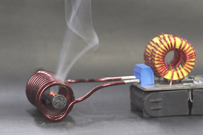
A high-frequency induction heating device is a device that heats by high-frequency induction.

When alternating current is passed through a coil containing a metal body, a magnetic field is generated by the current flowing in the coil, causing induction loss, or hysteresis loss, which generates heat. At the same time, eddy currents, or eddy currents, are generated in the changing magnetic field due to electromagnetic induction. These eddy currents generate Joule heat, which causes eddy current losses.

High-frequency induction heating equipment utilizes the two heating principles of hysteresis loss and eddy current loss. The energy supplied to the object to be heated per unit area and unit time is large, making high-speed heating possible.

Uses of High-Frequency Induction Heating Equipments

High-frequency induction heating is often used for melting, quenching, and brazing of metals because it can heat conductors such as metals without contact. A familiar example is the induction cooktop. Other applications include resins, wood, textiles, food, and medicine.

In the case of thermoplastic resins, induction heating can be used to weld resins while pressing them in a mold. In the case of food production, high-frequency induction heating equipment can be incorporated into factory lines to defrost food products rapidly when processing large quantities of food products.

In the medical field, high-frequency induction heating methods are also used in the development of cancer thermotherapy and other treatments.

Principle of High-Frequency Induction Heating Equipments

High-frequency induction heating is a method of heating an object using electromagnetic induction. It can be classified as a direct heating method or an indirect heating method, depending on whether the object to be heated is heated by passing an electric current directly through it or through a conductive container.

1. Direct Heating Method

The law of electromagnetic induction states that when an alternating current is applied to a coil, a magnetic flux is generated that passes through its center and surrounds the outside. Eddy currents are generated in the metal to prevent this magnetic flux from changing.

Depending on the magnitude of these eddy currents and the electrical resistance of the metal, Joule heat is generated in the metal. In the direct heating method, the object to be heated can be directly heated by generating eddy currents directly in the metal in this way.

2. Indirect Heating Method

The indirect heating method is used to heat insulators such as ceramics, which cannot generate eddy currents in the object to be heated. Therefore, indirect heating is possible by placing the object to be heated in a conductive container and heating the container.

To increase heating efficiency, the gap between the external shape of the object to be heated and the heating coil is reduced to increase the flux density transmitted. Furthermore, the heating is done by controlling the frequency of the AC power source between tens of Hz and hundreds of kHz.

Other Information on High-Frequency Induction Heating Equipment

1. Advantages of High-Frequency Induction Heating Equipment

Uniform Heating
The heat is generated by resistance heating against eddy currents generated by electromagnetic induction, so the heated object is uniformly heated from the inside.

Rapid Heating
By controlling the transmitter, high-frequency waves can be applied instantaneously to the object to be heated, and since the heating is internally self-heated, rapid heating is possible. Compared to heating furnaces that apply heat externally, this system is superior in productivity and requires no standby heating, making it a low-cost production method.

Selective Heating
Even for composite materials such as aluminum alloy and steel clad steel, only the portion of the material with high electrical resistivity can be selectively heated.

High Energy Efficiency
In general heating furnaces, external heating is done by combustion or heating elements, resulting in energy loss due to unnecessary heating of not only the object to be heated but also the furnace components and atmosphere. With high-frequency induction heating equipment, only the object to be heat-treated is heated by self-heating, thus eliminating waste and enabling heat treatment with high energy efficiency.

2. Disadvantages of High-Frequency Induction Heating Equipment

Expensive Capital Investment
High-frequency induction heating has the disadvantage that the initial capital investment is expensive because high-frequency induction heating equipment requires expensive high-frequency power supplies and control devices, as well as equipment to prevent electromagnetic radiation leakage to the surrounding environment.

Low Shape Selectivity
If the electric field of the object to be heated is non-uniform, the heat generation itself will also be non-uniform, resulting in uneven temperatures, which may lead to problems such as melting in the worst case. Therefore, the object to be heated should have a highly symmetrical shape, such as a cylinder. It is difficult to heat complexly shaped objects, such as square timbers or gears, evenly.

Individual and Partial Heating
High-frequency induction heating is a method of heating the whole or only a part of the object to be heated by means of an arbitrarily shaped coil designed to heat the object uniformly. For this reason, it is basically a one-piece flow process, and thus cannot perform batch-type mass simultaneous processing like external heating. Depending on the product and production conditions, this method has the disadvantage of reduced productivity.

カテゴリー
category_usa

High Precision Thermometer

What Is a High Precision Thermometer?

Precision Thermometer
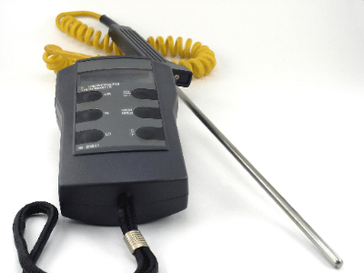
A high precision thermometer is a precision temperature measuring instrument that can measure temperature with the highest precision of any thermometer.

It is used together with a temperature sensor. By using a thermometer and a temperature sensor together, accurate temperature measurement is possible. Therefore, they are used to adjust temperatures and calibrate thermometers.

Thermoelectric sensors and resistance thermometer sensors are used as temperature sensors, each of which has different characteristics, so it is important to select a temperature sensor suitable for the intended use.

Uses of High Precision Thermometers

High precision thermometers are used to calibrate thermometers. By using a combination of temperature sensors, the temperature is adjusted to confirm that the calibration temperature of the thermometer in everyday use is correct. However, high precision thermometers are more expensive than ordinary thermometers, and their large size makes them less convenient to use.

The correct temperature data, pre-calibrated by the temperature sensor, is stored in memory, or in external memory for those types of high precision thermometers that do not have built-in memory. By reading the data in this memory, measurement with high accuracy can be made.

Principle of High Precision Thermometers

Precision-Thermometers_高精度温度計-1

Figure 1. Principle of thermometers

The most commonly used temperature sensors in the industry are thermocouples and resistance thermometers.

1. Thermoelectric Temperature Sensor

Precision-Thermometers_高精度温度計-2.

Figure 2. Thermocouple Temperature Tolerance

A thermoelectric temperature sensor is a temperature sensor that combines two different types of metal conductors. When a temperature difference occurs at the contact points of the different metals, a voltage is generated between the metals, and the Seebeck effect, which generates a thermoelectromotive force, is used to measure the voltage, thereby accurately measuring the temperature.

The characteristics of the thermocouple are its fast response and the ability to measure even at high temperatures due to its small size. It is often misunderstood that only the tip of the thermocouple (the part where the different metal wires are bonded) is the measurement part, but since the electromotive force generated between the different metal wires is the target of measurement, the temperature difference including the conductor part is important. The temperature tolerance is larger than that of the resistance thermometer.

2. Temperature Sensor Using Resistance Thermometer

Precision-Thermometers_高精度温度計-3.

Figure 3. Resistance Thermometer Tolerance

Temperature sensors using resistance thermometers are based on the principle of the electrical resistance of metals increasing as the temperature rises. Highly pure platinum or nickel is used as the material for the strands.

Compared to thermoelectric, they cannot be used at high temperatures and have a narrower coverage range. However, it is characterized by its ability to detect temperatures with very high accuracy in the low to medium temperature range and its high stability.

High precision thermometers are similar in principle to ordinary thermometers, but they use a higher class of thermometer, and their accuracy is maintained through thorough calibration and other measures.

Other Information on High Precision Thermometers

1. Measurement Error of High Precision Thermometer

No matter how strictly calibrated the specifications are, if the measurement is not appropriate for the environment, the correct temperature cannot be measured. Typical error factors are as follows.

Error Factors for Resistance Thermometers

  • Effect of self-heating due to energizing current
  • Influence of thermal shock due to temperature change of measurement object
  • Effects of vibration and shock

Other factors include the effects of abnormal voltages and currents (e.g., lightning strikes, high-voltage discharges, etc.) and the effects of low insulation resistance.

2. Error Factors of Thermocouples

Error factors for the most commonly used K-type thermocouples are as follows:

Oxidation in a Reducing Atmosphere
When K-type thermocouples are used in a high-temperature reducing atmosphere between 800 and 1,000°C, the measured value may deviate by several hundred degrees. This is because the surface oxide film of the chromel wire used on the + side of the K-type thermocouple is reduced by the reducing atmosphere and then oxidized to form NiCr2O4. In particular, hydrogen gas permeates through some metal protection tubes at high temperatures, so it is important to use a sheath material with low hydrogen permeability.

Effect of Sheath Mid-Temperature (Shunt Error)
If the sheath is in contact with a hotter part than the temperature to be measured, the temperature will be higher than the part to be measured. This is because the insulation resistance of the inorganic filler inside the sheath decreases at temperatures higher than 800°C. It is effective to pay attention to the installation method and select a sheath with a larger outer diameter to increase the insulation distance between strands.

Inevitable Error of K-Type Thermocouples (Short Range Ordering)
When K-type thermocouples are used at temperatures between 300 and 550°C, the EMF characteristics may change and errors may occur. This is because the metallurgical structure of the chromel alloy increases EMF at temperatures between 300 and 550°C. Heating to 650°C or higher will restore the original characteristics.

External Electrical Influences
Noise generated by generators, motors, etc. can cause errors. To minimize the effect of noise, use shielded compensating conductors. If a shielded compensating conductor is not used or a two-point grounding type is used, the shielding effect may be reduced or induced currents may be picked up instead.

Effects of Not Using Compensating Conductors
Thermal thermocouples do not measure the temperature at the tip, but rather the “temperature difference” between the tip and the area connected by a conductor, which is the electromotive force. Therefore, the part of the thermocouple that is connected to the conductor is the electromotive force generating part. However, if thermocouple wires are used for the entire measurement, the cost will be high and the resistance value will be too high, so compensating conductors are used.

A compensating conductor is a conductor that has almost the same EMF as the thermocouple used in combination. Sometimes the principle of the thermocouple is misunderstood and an ordinary conductor is used instead of a compensating conductor, or the conductor that should be used is mistaken.

In addition, both resistance thermometers and thermocouples are used to measure temperatures by making contact, so care must be taken with the method of contact and the external ambient temperature.