What Is a Universal Joint?
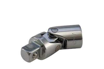
A universal joint is a joint that connects two rotating shafts or pipes. enabling them to rotate freely even when the shafts are not concentric (meaning their longitudinal centers are not the same) or when there is an angle between them. The term “universal joint” is also used as a synonym.
For example, drive shafts that transmit power are installed in a limited installation space, so there are cases where the shafts cannot be concentric with each other. By using a universal joint, a drive shaft and a driven shaft can be connected.
Uses of Universal Joints
Universal joints are used in situations where two rotating shafts or tubes cannot be joined concentrically due to structural or installation space limitations.
Examples of universal joints include propeller shafts and drive shafts in automobiles, steering wheels, steering shafts, and steering gearboxes.
Universal joints are also used when pipes are not concentric with each other but are at an angle.
Principle of Universal Joints
In universal joints, the shaft centers of the two pipes are inclined at an angle α. When shaft 1 (drive side) rotates at a constant angular velocity ω1, shaft 2 (driven side) rotates at an angular velocity ω2, calculated by the following equation:
(θ = angle of rotation of shaft 1)
ω2=(COS α / (1-SIN2 θ x SIN2 α)) x ω1
Between Shafts 1 and 2 of a single universal joint, the speed increase and decrease are repeated every half revolution, and constant speed rotation is not achieved. Therefore, when a single universal joint is used, it is used only for applications where this unequal speed is not so important.
When three shafts, shaft 1, shaft 2, and shaft 3, are arranged in the same phase in a row with two universal joints, this unequal velocity is canceled out between Shaft 1 and Shaft 3, resulting in constant velocity.
Typical types of universal joints are as follows:
1. Cardan-Type Shaft Joint
This type of joint consists of two shafts that are split at one end (U-shape), and a metal fitting with pins arranged in a cross shape is inserted in the two shafts.
2. Barfield-Type Shaft Coupling
One shaft incorporates an “outer race” and the other an “inner race.” Grooves are machined on the inner surface of the outer race and the outer surface of the inner race, which are connected by both races, for the placement of steel balls.
The movement of the steel balls allows the transmission of rotational speed even if the shafts are angled toward each other. Even when the Barfield-type shaft coupling is used singly, shafts 1 and 2 rotate at a constant speed.