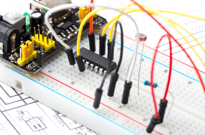
What Is a Jumper Cable?

A jumper cable is a tool used to create short circuits between two points in electronic circuits and control panels. These cables are integral in printed circuit boards, control panels, and breadboards for experiments, allowing for quick and simple shorting or opening between points. They facilitate easy switching between multiple circuits.
Uses of Jumper Cables
Jumper cables are essential in various electrical circuit applications, including:
- Diagnosing electrical circuit failures.
- Evaluating operations of printed circuit boards and control panels.
- Conducting experiments on breadboards.
- Setting operations on printed circuit boards.
Primarily, they are used for temporary configuration changes in electrical circuits. However, incorrect use can lead to dangerous short circuits in power supply circuits. Therefore, careful examination of circuit diagrams and manuals is necessary before application.
Principle of Jumper Cables
Most jumper cables use vinyl-insulated wires made of copper and coated with vinyl. They can have either stranded or single-core wires, based on the application. The wire ends typically have a clip or terminal, such as minnow clips, round terminals, or breadboard sockets. The length of jumper cables usually does not exceed 1 meter, as they are often used for nearby short-circuiting tasks.
Types of Jumper Cables
Jumper cables vary in terminal types, with common examples including:
1. Male Pin Terminals
These have pins on the ends, suitable for insertion into breadboards or female sockets.
2. Female Pin Terminal
Designed to plug into male pin terminals, commonly used for microcontroller boards like Raspberry Pi.
3. Minomushi Clip Terminal
Feature metal clips on the ends, allowing easy connection and disconnection with various wire thicknesses.
Jumper cables can have “male,” “female,” or a combination of these ends. U-shaped jumper wires are used for equidistant connections on breadboards.
Other Information on Jumper Cables
1. Color of Jumper Cables
They often come in 2 or 4 cores, especially for use in telephone terminal boards. The color coding, while not standard, aids in maintenance and identification.
2. Setting Circuit Constants Using a Breadboard
Breadboards and jumper cables are used to determine optimal constants for electronic circuits. A breadboard allows for component insertion and circuit assembly for experimental purposes. By connecting jumper cables to different resistors, various circuit configurations can be tested and evaluated.