What Is a Gate Valve?

A Gate Valve is a valve that closes a flow path by shutting off a fluid, such as a liquid or gas, with a disc (valve disc).
Generally, “gate valve” and “slew valve” are also used as synonyms. Gate valve is defined in JIS B0100 Glossary of terms for valves as “a generic term for valves in which the valve plug vertically divides the fluid flow path to open or close it, so that the fluid flow is in a straight line.
Gate valves are said to be so called because the disc (valve disc) slides into the flow path like a gate in a sluice gate and shuts it off.
Applications of Gate Valves

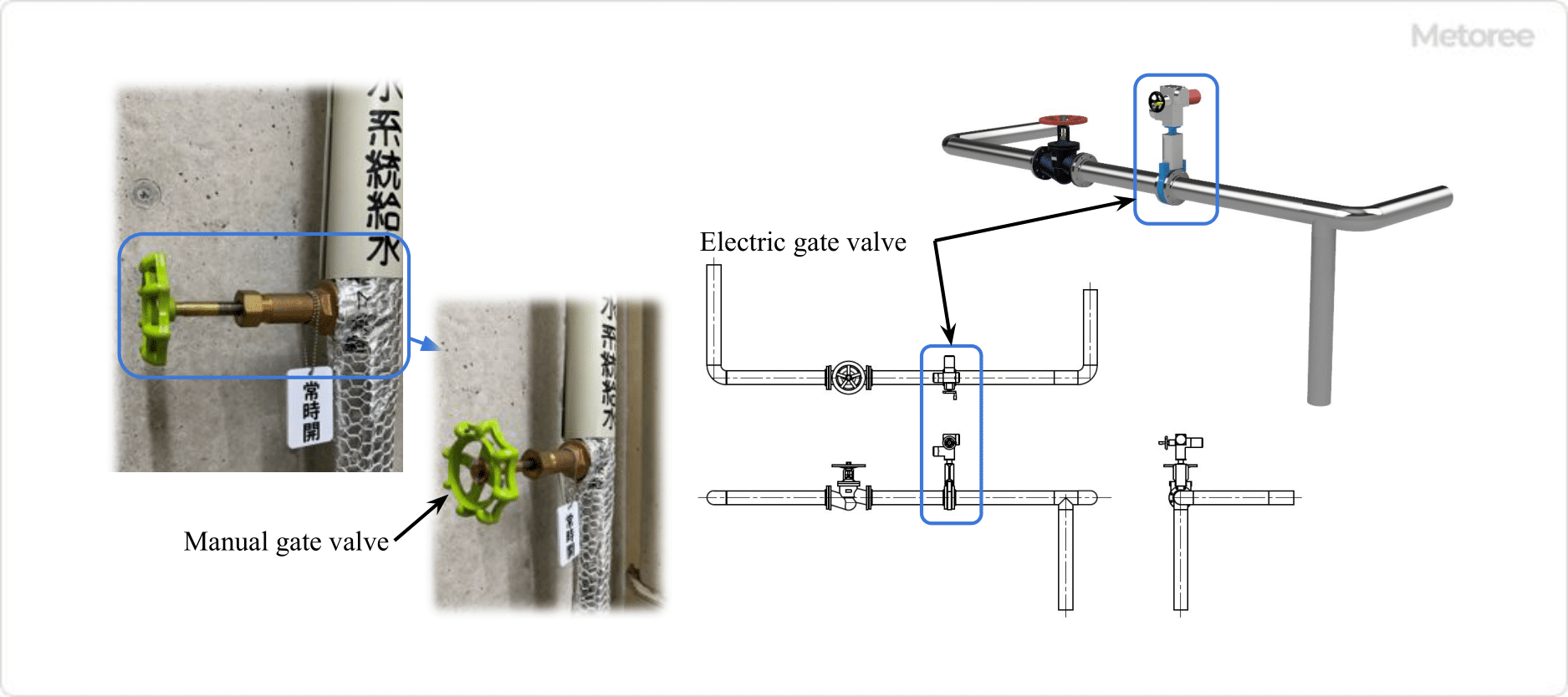
Figure 1. Example of gate valve use
Gate Valves are used in a wide range of applications, from households to general industry to academic research, because they can control fluid flow over a wide range of pressures and temperatures. Familiar examples include water meters, gas meters, and piping for water heaters.
Gate Valves, in particular, are usually used in the fully open or fully closed position because the disc vibrates when used in the middle opening position. Therefore, these valves are used for shutoff purposes as stop valves.
Generally, gate valves are installed as shutoff valves in pipelines and water supply pipelines, either permanently open or closed. Manual Gate Valves require a lot of turning of the handle, which makes opening and closing the valve time-consuming.
Therefore, when opening and closing the valve very frequently or operating it remotely, a gate valve equipped with an actuator for automatic opening and closing is used.
Principle of Gate Valve

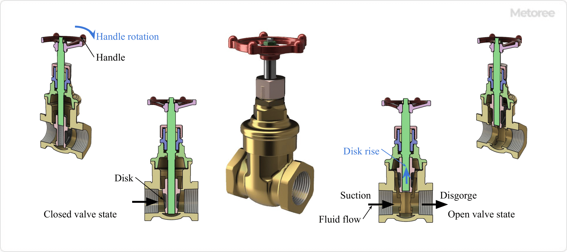
Figure 2. Gate valve open/close valve state and fluid flow
The principle of a Gate Valve is very simple: when open, the disc (plug) is lowered by the body (valve box), shutting off the flow path and closing the fluid. A closed valve, on the other hand, raises the disc and opens the flow path to allow fluid to flow.
The disc is raised and lowered by a screw mechanism on the stem, which is rotated by a handle or actuator.
1. Pressure drop across the Gate Valve
Gate Valves are often designed as full-port valves and feature an extremely small pressure drop when fully open because there is little difference in the flow path area between the inside of the body and the inlet/outlet piping, and the flow path is nearly straight.
In addition, Globe Valves, which are often used as stop valves in the same way as Gate Valves, have an S-shaped flow path inside the body, so the pressure loss at full opening is larger than that of Gate Valves.
The pressure loss is the amount of energy lost when a fluid passes through a pipe. It is caused by friction loss due to the inner wall of the pipe and the generation of turbulence.
2. Gate Valve Water Hammer Phenomenon
Gate Valves are less prone to water hammer phenomenon because they have a relatively large stroke when opening and closing, and cannot open and close abruptly. Water hammer refers to a transient rise or fall in pipe pressure caused by a sudden change in flow velocity when the valve is opened or closed rapidly.
Pressure fluctuations due to water hammer can cause the following problems
- A sudden rise in pressure damages the piping, connected pumps, valves, and other equipment, and piping support hardware.
- Sudden pressure drop causes deformation of the piping and secondary pressure increase due to water column separation, resulting in damage to the piping
- Pressure fluctuations make pressure control difficult
Gate Valve Structure

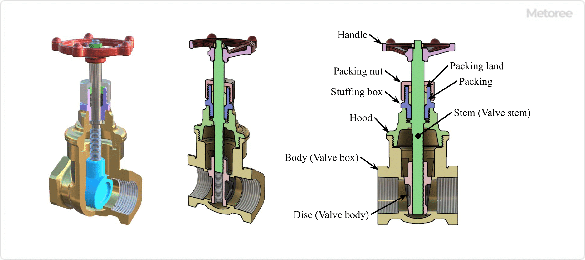
Figure 3. Structure of gate valve
Gate Valves are mainly composed of a body (valve box), a disc (valve plug), a stem (valve stem), and a handle. Gate Valves can be operated by a handle or an actuator.
The handle is attached to the stem and transmits rotation to the stem. When the valve is open, rotation of the handle causes the stem screw to rotate in a direction that raises the disc, and the opposite rotation causes the disc to rotate down when the valve is closed.
Types of Gate Valves
1. Classification by opening/closing operation method

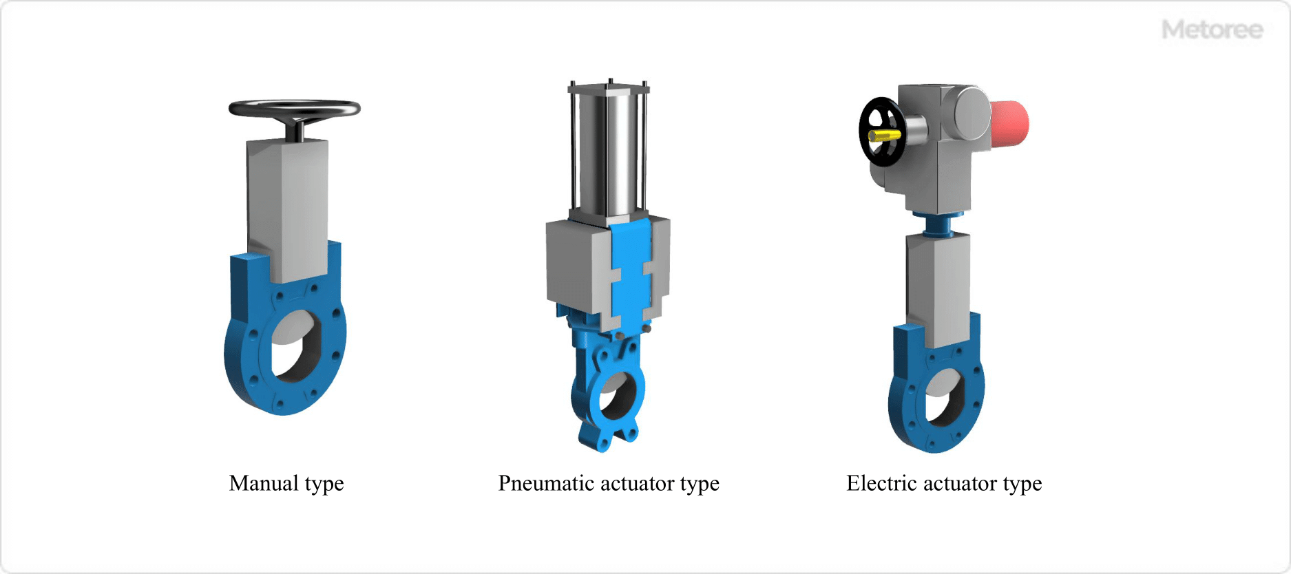
Figure 4. Gate valve operation and drive system
Gate Valves have the following three main types of operating and driving methods to open and close the valve.
- Manual Type
Rotating the stem with a handle, etc. - Air-actuated Type
Pneumatic actuator rotates the stem - Electric Type
Rotate stem by electric actuator
2. Classification by Disc Shape and Structure
Gate Valves are classified by disc shape and construction as follows
- Parallel or wedge disc
Discs with “parallel” or “wedge” cross section - Parallel Slide
Combination of two discs parallel to each other, which, due to fluid pressure, exerts a surface pressure on the outlet side seat (valve seat) surface - Double Disc
Consisting of two discs, the stem pushes the discs apart to apply pressure to the inlet and outlet seat surfaces.
3. Stem lift type and non-rising type
Gate Valves have a stem that rotates to move the disc up and down, but does not change position as the stem rotates.
Stem Ascending Type
In the stem lift type, the position of the stem or handle rises or falls with stem rotation. The degree of opening and closing can be determined by the position of the stem or handle, so the condition can be checked visually.
Also, since the stem or handle rises, a space is required to operate the handle.
Stem non-rising type
In the stem lift type, the stem or handle position does not rise or fall with stem rotation. Since the degree of opening and closing cannot be determined by the position of the stem or handle, it is not possible to visually check the state of the stem or handle.
Also, since the stem or handle does not rise, the space for operating the handle is smaller.
4. Classification by Body Material
Gate Valve materials can be classified by the material of the body. Common body materials are as follows
- Gray cast iron JIS G5501 FC200
- Spheroidal graphite cast iron JIS G5502 FCD400
- Carbon steel forgings for pressure vessels JIS G3202 SFVC 2A
- High temperature and high pressure cast steel products JIS G5151 SCPH2, SCPH21
- Stainless steel castings JIS G5121 SCS13A, SCS14A
- Copper and copper alloy castings JIS H5120 CAC406 Bronze castings class 3
- Copper and copper alloy rods JIS H3250 C3771 Brass for forging
Body materials are selected based on the following requirements. For details, refer to each manufacturer’s catalog, etc.
- Fluid type, pressure, temperature, flow velocity, and presence/absence of impurities
- Corrosion resistance required or not
- Applicable regulations and standards