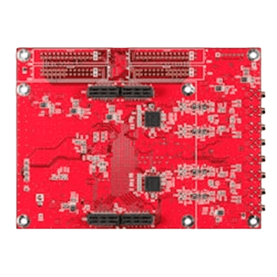
What Is an Analog-To-Digital Converter Board

An Analog-To-Digital Converter is a board that has the function of converting various analog signals into digital signals. They are available with various interfaces for embedded applications.
Products with interfaces such as PCI-Express for built-in PCs, FMC for connection as a daughter card to other boards, and USB are available.
Analog-To-Digital Converter Board Applications
Analog-To-Digital Converter Boards are mainly used to convert analog signals acquired by various sensors into digital signals for processing by microcontrollers and other devices.
1. Measurement and Monitoring
Analog-To-Digital Converter Boards are used to convert physical quantities such as temperature, pressure, light, and sound into digital signals. This allows signals from sensors to be acquired for measurement and monitoring. Examples include product quality control in factories and environmental monitoring.
2. Data Acquisition and Processing
Analog-To-Digital Converter Boards are used to acquire and process data by converting analog signals to digital signals. Examples include the acquisition of ECG signals in medical equipment and audio processing.
3. Signal Processing
Analog-To-Digital Converter Boards are used to perform digital signal processing. Examples include audio filtering and waveform analysis.
Principle of Analog-To-Digital Converter Boards
A/D conversion converts an analog signal to a digital signal through the following sampling, quantization, and encoding steps.
1. Sampling
The amplitude value of an analog signal, which is a continuous signal, is sampled at discrete periods. The period at this time is called the sampling period and is mainly expressed by the symbol Ts. The calculation formula is as follows:
Sampling period: Ts = 1/Fs (Fs: sampling frequency)
2. Quantization
The amplitude value cut out at a discrete period (sampling period) by sampling is approximated to a discrete amplitude value so that it can be converted into a digital signal.
The error produced by quantization is called quantization error and is expressed by the following equation:
Quantization error = (sampled value) – (quantized value)
Quantization is performed by comparing the input voltage with a reference voltage. Depending on the method of comparison, there are methods that enable high-precision conversion and high-speed sampling.
3. Coding
The discrete amplitude value approximated by quantization is converted into a binary code of 0 and 1.
Types of Analog-To-Digital Converter Boards
Analog-To-Digital Converter Board types are classified according to the AD conversion method. The three main methods are as follows:
1. Successive Comparison
The successive comparison type AD conversion method converts an analog signal into a digital signal by comparing voltages. The analog signal is compared with the voltage to be compared, and the bits are determined one after another.
The maximum resolution is 18 bits and the maximum sample rate is about 10 MHz. An external anti-aliasing filter is required.
2. Delta-Sigma
The delta-sigma type AD conversion method uses delta-sigma modulation technology to convert analog signals to digital signals. It is the method that provides the highest resolution with a maximum resolution of about 32 bits, but it is slow with a maximum sampling rate of about 1 MHz.
3. Pipeline
The pipelined AD conversion method divides the analog signal into multiple stages in a pipeline structure and processes them in parallel to achieve high-speed conversion. Each stage converts the analog signal into a digital signal and passes it to the next stage.
The maximum sample rate is 1 GHz and the maximum resolution is about 16 bits. The cost is high because of the complexity of the circuit.
How to Select an Analog-To-Digital Converter Board
1. Resolution
Select an Analog-To-Digital Converter Board with the required resolution. For example, if the board is to be used for feedback control, determine the resolution based on the accuracy requirements.
2. Sampling Period
Determine the sampling period according to the frequency range of the target signal. Theoretically, a sampling period of twice the frequency range is required, but in practice it is said to be 10 times.
3. Number of Input Channels
Analog-To-Digital Converter Boards come in a variety of types, ranging from those with one channel to those with several hundred channels. Depending on the number of signals to be measured, the required number of input channels should be selected.
4. Input/Output Interface
Analog-To-Digital Converter Boards often have interfaces such as USB, FMC, and PCI Express. The appropriate interface should be selected according to the interface used.
5. Software
Analog-To-Digital Converter Boards may come with measurement software. This software provides functions such as data acquisition, processing, display, and storage. Depending on the purpose of use, it is necessary to check whether software with the required functions is available.
6. Cost
Depending on the required accuracy, sampling rate, and number of input channels, an appropriate price range should be selected.