What Is a Shunt Regulator?
A shunt regulator is an integrated circuit (IC) that monitors the input voltage of a circuit and applies feedback to maintain the output voltage constant.
Generally, the voltage in an integrated circuit deviates or varies due to various factors such as temperature change and individual component differences. On the other hand, shunt regulators are also called reference voltage integrated circuits because they can control voltages with high accuracy and are often used as a reference voltage source.
Compared to voltage stabilizing circuits such as linear regulators and switching regulators, shunt regulators are characterized by their ability to control voltage with high precision.
Uses of Shunt Regulators
Shunt regulators are widely used in applications that require high-precision reference power supplies, such as reference voltage sources for AD/DA converters and DSP refs, along with high-precision control of electronic devices.
Although shunt regulators are capable of high-precision voltage control, their efficiency is very low, especially when operating under high currents, due to their function of constant voltage in parallel with the load. Therefore, they are used as a reference voltage source under low-current load conditions where their low efficiency is negligible. They are also used to drive another high-current regulator in series with them in the subsequent stage.
For example, in a logic circuit that compares two voltages, such as a comparator, the reference voltage is used as the comparison target. If the reference voltage drifts, the intended circuit operation itself may fail, so the reference voltage value must be as stable as possible.
Principle of Shunt Regulators
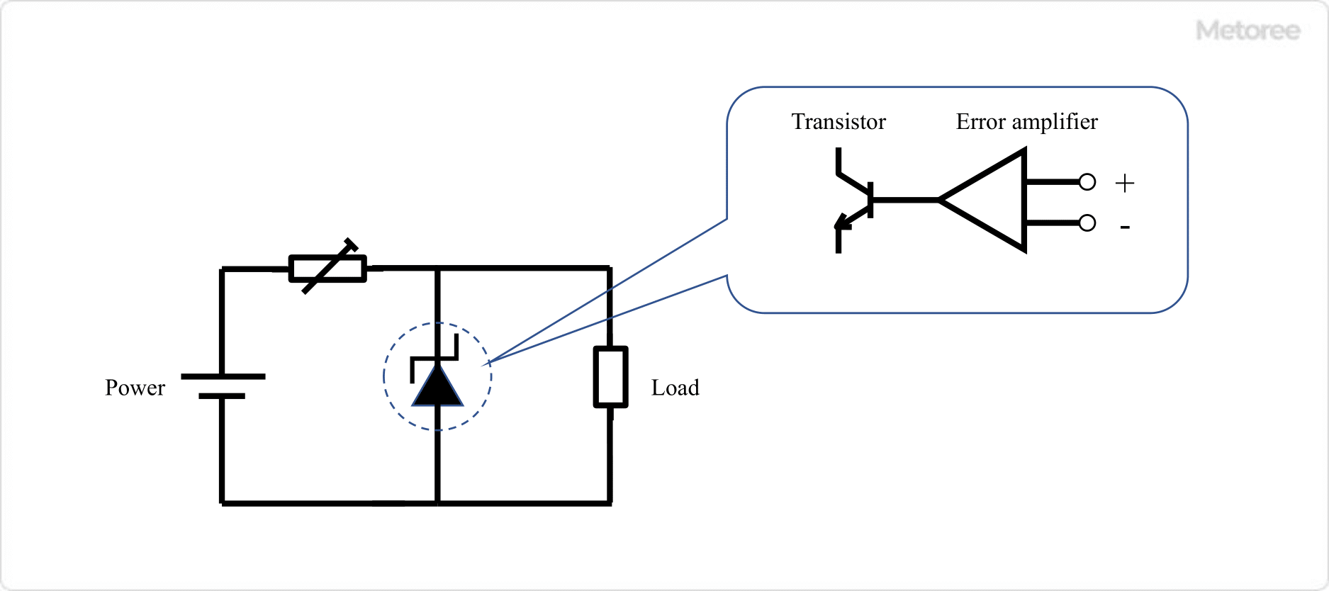
Figure 1. Principle of a shunt regulator
The operating principle of a shunt regulator is that its components, an error amplifier and transistor connected in parallel with the load, compensate for input voltage fluctuations and maintain a constant load current, resulting in a highly accurate voltage value.
A general shunt regulator consists of an internal reference voltage pin, an error amplifier, and a transistor, which are connected in parallel to the load in the circuit. When the input voltage rises, the output voltage tries to rise along with it. However, the error amplifier senses this and increases the current flowing to the transistors, thereby decreasing the current flowing through the load and suppressing the rise in output voltage.
The simplest example of a shunt regulator is a Zener diode regulator. Unlike a normal diode, a Zener diode has the characteristic of applying a voltage in the reverse direction and when it exceeds a certain threshold, a large current begins to flow. The threshold voltage is called the Zener voltage. The Zener voltage can be accurately designed by adding impurities to the PN junction.
Shunt regulators that make good use of this diode characteristic can obtain a constant voltage with only a diode, which leads to the simplification of circuits and cost reduction. However, due to large temperature fluctuations, shunt regulators composed of error amplifiers and transistors should be used when temperature characteristics are important.
Other Information on Shunt Regulators
1. Difference Between a Series Regulator and a Shunt Regulator
Linear regulators are DCDC converters that produce an output voltage lower than the input voltage, and they can be classified into two types: series regulators and shunt regulators.
Shunt regulators are DCDC converters that use resistors for voltage drop generation and control elements that control the load in parallel and are also called parallel control types. On the other hand, a series regulator has control elements in series with the load and is also called a series control type.
Unlike series regulators, shunt regulators are characterized by the continuous flow of a set current. They tend to have high reactive power and are not suitable for high-current applications.
2. Three-Terminal Regulator and LDO
Unlike shunt regulators, series regulators, which are also used for high-current applications, can be classified into two categories: three-terminal regulators and LDOs (Low Dropout Regulators). Three-terminal regulators consist of a device with three terminals: input, output, and GND. Generally, switching regulators are used in DC power supply circuits because of their high efficiency, but three-terminal regulators are used in some applications because of their low noise, few external components, and low cost.
LDOs are series regulators that can operate with a small input-output potential difference and have the advantage of lower power loss than general-purpose series regulators. However, due to its operation, some precautions must be taken in its use, such as input voltage limits and load conditions, so it is important to check the specifications.