What Is a Linear Regulator IC?
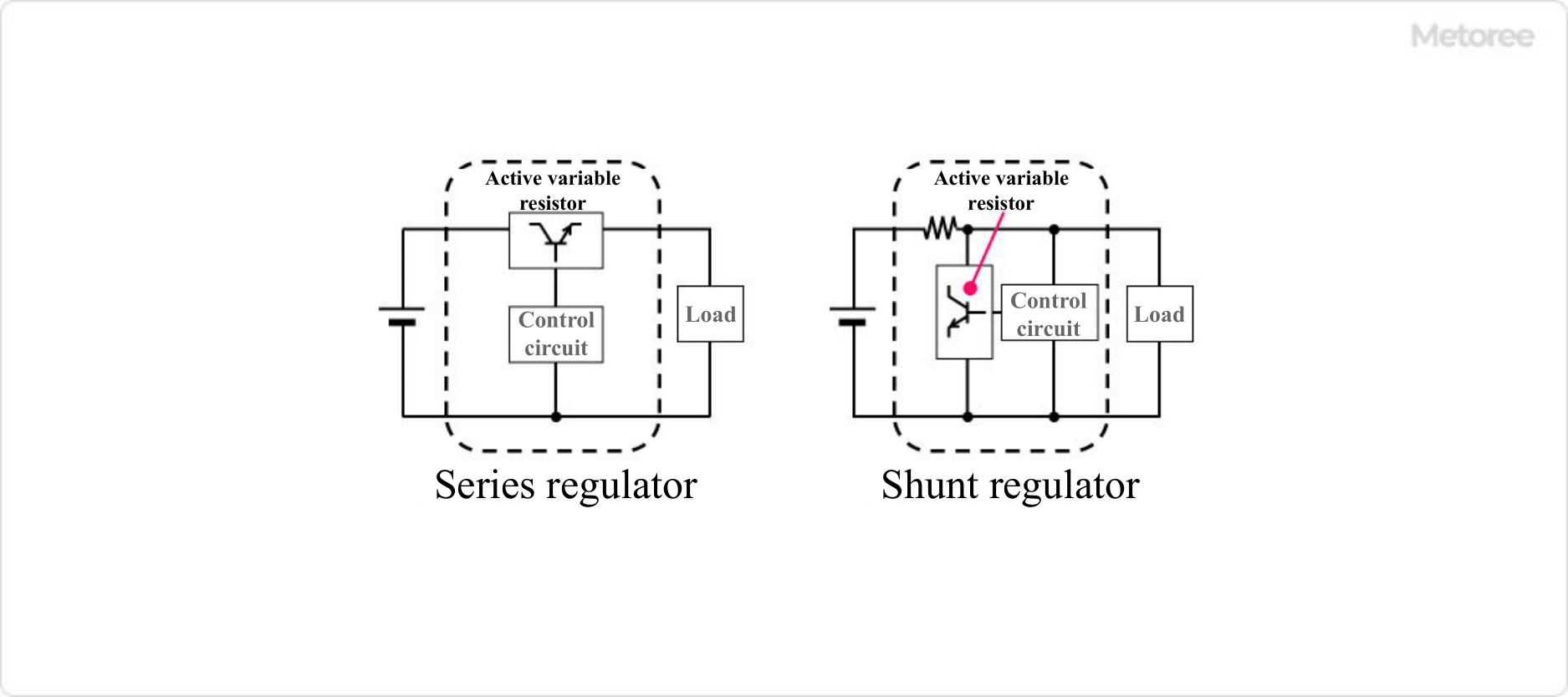
Figure 1. Types of linear regulators
A Linear Regulator IC is an electronic component that outputs a stable voltage.
A constant voltage is output from the output terminal by using the voltage drop of a resistor or semiconductor device in relation to the input voltage. Since a small output voltage relative to the input voltage results in a large voltage difference loss, linear regulator ICs are used as power supplies for circuits and sensors that operate with low power consumption.
Among Linear Regulator ICs, a series regulator is an active variable resistor IC using semiconductor elements connected in series, and a shunt regulator is an active variable resistor IC connected in parallel.
Uses of Linear Regulator ICs
Linear Regulator ICs are used as the power supply part of electronic equipment and precision instruments that operate on low power. Because of the simplicity of their circuits, many products are available in low price ranges, and they are characterized by excellent stability of the voltage of the power supply they supply and low noise.
Among Linear Regulator ICs, Series Regulator ICs should not exceed the absolute maximum operating temperature of the IC because of the heat generated during the voltage drop with active variable resistor elements. If the regulator IC generates a lot of heat, measures such as attaching an external heat sink must be taken if necessary.
Principle of Linear Regulator ICs
Linear Regulator ICs are one of the most common 3-terminal regulators. 3-terminal regulators have three terminals: input, output, and ground. 3-terminal regulators have the same basic structure.
A power supply is connected to the input terminal, an input capacitor is connected between the input terminal and ground, and an output capacitor is connected between the output terminal and grant so that a constant voltage is output from the output terminal.
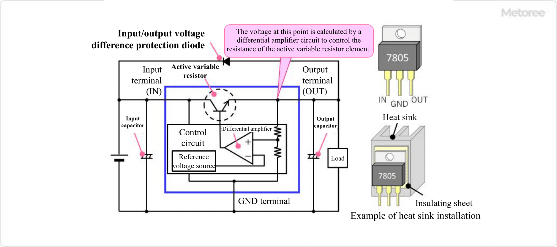
Figure 2. Principle of the three-terminal regulator
Inside a Linear Regulator IC is a control circuit consisting of an active variable resistor element using transistors or FETs and a reference voltage source. The control circuit measures the voltage passing through the active variable resistor element, performs feedback control, and controls the resistance value of the active variable resistor element, thereby controlling the magnitude of the voltage output from the output terminal to a certain level.
Because active variable resistor elements generate a voltage drop above a certain voltage, an input voltage that exceeds the minimum difference between the input voltage and output voltage, called the dropout voltage, is required to output a stable power supply. Normally, this is about 1.5 V. However, the IC should be selected with attention to the minimum input voltage.
Other Information on Linear Regulator ICs
1. Precautions for using 3-Terminal Regulators
Heat Dissipation of 3-Terminal Regulators
The product of the voltage difference between the input and output terminals and the current flowing from the output terminal (output current) generates heat inside the regulator and consumes power. Therefore, the larger the difference between input voltage and output voltage, and the larger the output current, the more heat is generated.
Therefore, heat dissipation design is an important factor when using 3-terminal regulators. To dissipate heat efficiently, an appropriate heat sink should be designed and attached to the 3-terminal regulator.
Board Design of 3-Terminal Regulators
The 3-terminal regulator operates to constantly output a stable voltage by feeding back the output voltage. Therefore, the capacitors connected between the input pin and GND and between the output pin and GND are very important. In particular, if the capacitor on the output pin is not appropriate, the output voltage may be transmitted.
In general, the capacitor recommended by the manufacturer of the 3-terminal regulator should be selected, but even in this case, the capacitor should be placed as close to the 3-terminal regulator as possible, and the board pattern between the 3-terminal regulator and the capacitor should be shortened in the board design.
Protection of 3-Terminal Regulator
If some abnormal voltage is expected to be applied to the input or output, a circuit to protect the 3-terminal regulator is required. If there is a possibility that an instantaneous high voltage may be applied to the input side, add a damping resistor or a Zener diode to the input to clamp that high voltage.
Countermeasures are also required when the input voltage may drop below the output voltage. If for some reason the input voltage drops significantly, a capacitor with large capacitance must be connected to the output terminals to maintain a constant output voltage. As a corollary, the output terminal voltage may temporarily be higher than the input terminal voltage when the power supply is turned off, for example.
Also, in a circuit that combines multiple power supplies, there is a possibility that the output voltage may be higher than the input voltage due to the power supply circulating from other power supplies. As a countermeasure, a protective diode (input side connected to cathode and output side connected to anode) can be added to allow current to flow from the output terminal to the input terminal.
2. Features of LDO Type Regulator
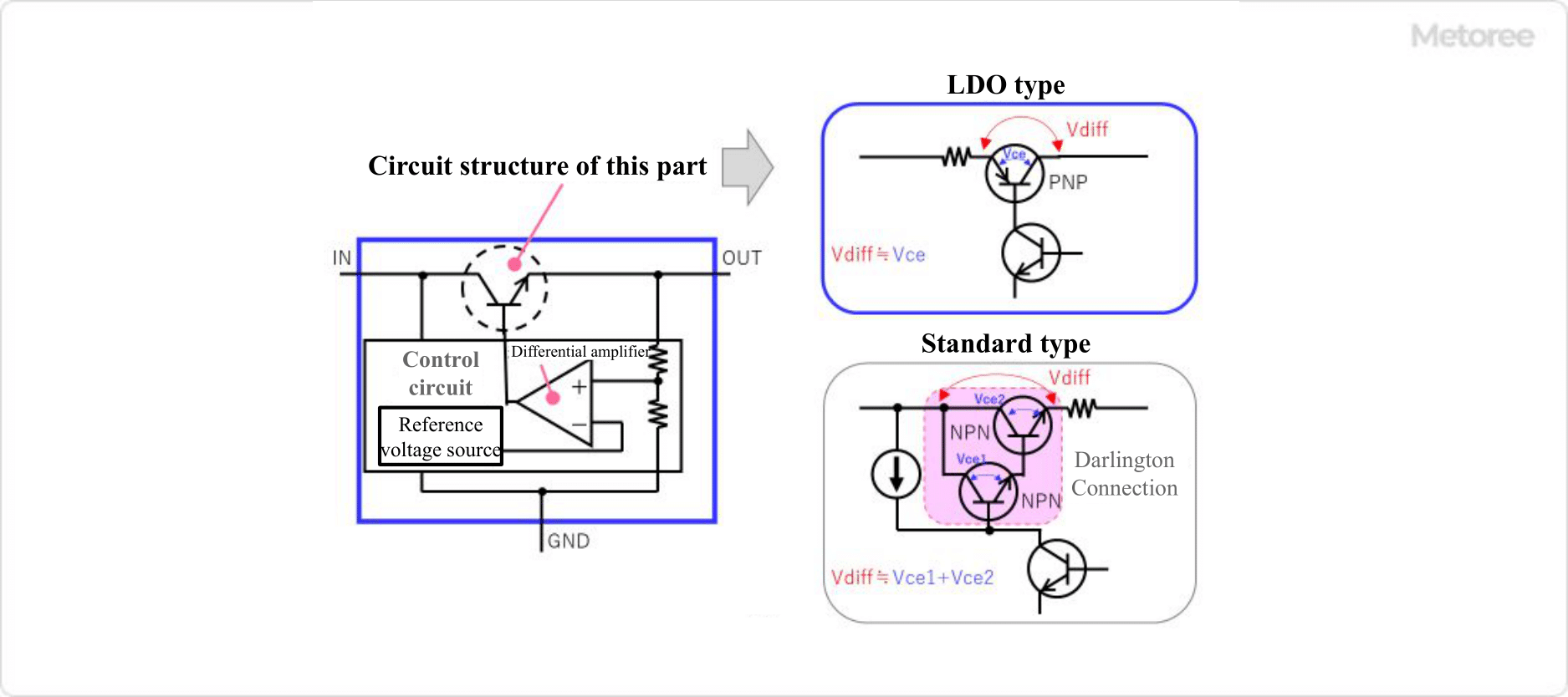
Figure 3. Features of LDO-type regulators
Three-terminal regulators are classified into “standard type” or “LDO type” according to the magnitude of dropout voltage (the amount by which the output voltage drops relative to the input voltage).
The dropout voltage of the standard type is about 3.0V, while the LDO type is characterized by a dropout voltage of less than 1.0V, which is smaller than the standard type. LDO” is an abbreviation of “Low Drop Out. When the combination of 12V input voltage and 5V output voltage was common, 3-terminal regulators were widely used to convert 12V to 5V. In this case, standard regulators with a dropout voltage of about 3V could be used without problems.
However, when 3.3V digital ICs became mainstream and the input voltage was 5V and the output voltage was 3.3V, LDO-type regulators became indispensable to convert 5V to 3.3V on the board. The standard type output circuit using bipolar transistors consists of two NPN transistors with Darlington connections, but the LDO type output circuit uses a single PNP transistor. This allows operation with a small dropout voltage.
However, the negative feedback characteristics have also changed, and the LDO type has a narrower stable operating range and is more prone to oscillation than the standard type. Therefore, the capacitance and ESR (equivalent series resistance) characteristics of the capacitor connected to the output pin are extremely important factors for the LDO type.