What Is an Analog Oscilloscope?
 An oscilloscope is a measuring instrument that observes changes in electrical signals over time.
Unlike testers, which only measure voltage and current at a certain point in time, oscilloscopes can observe the period and frequency of an electrical signal, the rising state of the signal, and the time and phase differences between multiple signals.
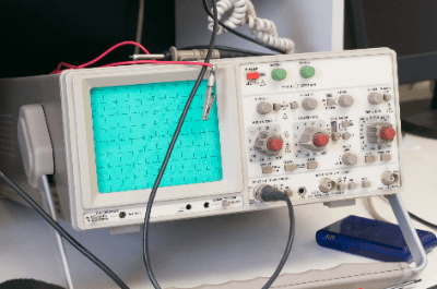
An analog oscilloscope is a type of oscilloscope that displays the time variation of an input signal on a CRT (cathode-ray tube) screen and observes its waveform.
Compared to digital oscilloscopes, which sample input signals at discrete time intervals and convert the data, analog oscilloscopes have a faster waveform update rate.
Uses of Analog Oscilloscopes
Oscilloscopes can observe electrical signals such as voltage, current, and frequency in electrical circuits as waveforms on the horizontal time axis. As a result, they are used to verify and debug the operation of all electrical circuits in industrial and consumer equipment during development and to analyze failures after products are shipped.
Analog oscilloscopes used to be widely employed due to their advantages over digital oscilloscopes, including faster waveform update rates and the absence of dead time.
However, since 2000, digital oscilloscopes with faster screen update rates and lower prices have become popular, and analog oscilloscopes are not widely used today.
Principle of Analog Oscilloscopes
Analog oscilloscopes display real-time changes in input signals on a CRT screen.
The back of the CRT is coated with a fluorescent film, and the fluorescent film emits light where the electron beam strikes it, producing a bright spot that is brighter than the rest of the screen. The trajectory of the bright spots can be observed as a waveform.
In analog oscilloscopes, the sensitivity of the input signal is adjusted with an attenuator, the amplitude is adjusted with an amplifier, and then the signal is applied to the vertical polarizer of the CRT through a delay cable and a vertical polarizer. This vertical polarizer moves the electron beam inside the CRT in the vertical direction by a distance proportional to the magnitude of the input signal.
On the other hand, the input signal branched from the amplifier goes through a trigger circuit to generate a sawtooth wave. The sawtooth wave is applied to the CRT’s horizontal polarizer through a horizontal amplifier. An analog oscilloscope achieves stable waveform observation by displaying the waveform on the CRT only during the period when the sawtooth wave rises.