カテゴリー
category_usa

Helisat Screw

What Is a Helisat Screw?

A Helisat screw is one of the thread inserts used to repair or strengthen the female threads in threaded fasteners.

In the Japanese industrial world, threaded inserts are widely used under the name of Helisert. Helisert is also one of the threaded inserts, but it is a registered trademark of Tsugami Corporation. In addition, the name was changed to E-sert in 2001. 

Applications of Helisat Screws

The Helisat screw is used to strengthen threaded holes in various plastic materials such as nylon, plastic, and Duracon, and other soft metals such as die-cast and aluminum. Heliserts can also be used to strengthen female threads when tapping into the base material alone will not provide tightening force, or to repair female threads that have been destroyed due to over-tightening torque.

The Helisat screw is widely used in automotive parts, transportation equipment, space industry, electronics, medical equipment, imaging equipment, agricultural machinery, playground equipment, musical instruments, etc.

Principle of Helisat Screws

Screw inserts, not limited to the Helisat screw, are used to strengthen a threaded hole or to rebuild a damaged threaded hole by screwing and embedding a threaded hole made of a strong material into the target threaded hole.

In other words, in order to use a Helisat screw, a pre-drilled hole of a larger size than the screw used for fastening is required. For example, a M8x1.25 Helisat screw has a M10x1.0 male thread on its outside diameter. Therefore, a M10x1.0 pre-drilled hole is required for the threaded hole to be strengthened.

To insert a Helisat screw, a special jig is used. There are two types of jigs: manual and electric. The electric jig uses an electric screwdriver to improve work efficiency.

Both manual and electric jigs require a special jig that matches the size of the Helisat screw to be inserted. A dedicated jig is also used to remove Helisat screw.

Other Information About Helisat Screws

 The Helisat screw is a spring made of stainless steel wire with a diamond-shaped cross section, while Helisat screw is an integral part made by cutting from a steel bar. The advantages over Heliserts are as follows:

1. No Need to Fold the Tongue After Insertion

Heliserts have a tang, which is used for screwing in the insert, and requires a folding operation to remove the tang after insertion. Helisat screw, on the other hand, has no tongue, so there is no need to remove it after insertion. 

2. No Pitch Jump

When the spring of a helical insert is stretched, the pitch of the thread is lost and the screw cannot be inserted, resulting in pitch jumps. Helisat screws, on the other hand, are one piece, so pitch jumps do not occur.

3. No Change in Shape

When a screw is inserted and removed repeatedly using a helical insert, the spring at the mouth of the screw may stretch and prevent the screw from being tightened. The one-piece Helisat screw does not change its shape in this way. 

4. Good Insertion Workability

Insertion of helical inserts requires a certain degree of skill and takes about 20 seconds. Helisat screw, on the other hand, requires no skill for insertion, which is said to take only 4 to 5 seconds. 

5. Pre-holes Can Be Drilled With Commercially Available Taps

The bottom hole of a helical insert is drilled with a dedicated tap. With a Helisat screw, a commercially available tap can be used for the pre-hole.

6. Adhesives Can Be Used

With the Helisat screw, adhesives can be used to secure the screw inserts firmly. Because of the spring structure of the helical insert, the adhesive will leak into the inside of the insert through gaps. Helisat screw is a one-piece unit, so no adhesive will leak into the insert.
カテゴリー
category_usa

Ion Counter

What Is an Ion Counter?

An ion counter is a device that is supposed to measure air ions, which are charged particles suspended in the air, especially negatively charged small ions.

With the negative ion boom in the 2000s, various types of ion counters are now available to measure the amount of negative ions in the environment.

For highly accurate measurement, it is desirable to measure both negative and positive ions at the same time, but there are also types that display only negative ions. This type is often used for sales promotions of home appliances, etc., where only negative ion values are to be displayed.

Uses of Ion Counters

Ion counters are used for research and industrial purposes at universities and companies. They are also used as sales promotion equipment to indicate the amount of negative ions generated by home appliances.

Since negative ions have become a popular topic of conversation about their health benefits, they have become more and more visible to the public as a machine that detects negative ions.

Principle of Ion Counters

The Ebert measuring device is the basic principle for measuring air ions, and the Gerdien method, an application of the Ebert measuring device, is the current mainstream method. In the Gerdien method, a voltage is applied to the outer cylinder of a double-cylinder device, and when a fan is used to inject a constant flow of air into the cylinder, positive ions are measured when the voltage is positive, and negative ions are measured when the voltage is negative.

Since each ion in the air has a different mobility, the mobility of the ions that can be supplemented by the ion counter is called the critical mobility. Ions with mobility greater than the critical mobility are captured by the Ion Counter, while ions with mobility less than the critical mobility are not captured.

If the voltage is increased, a point appears at which the current becomes constant, and if there were only small ions, all small ions would be captured by the ion counter. The following equation expresses the concentration of small ions at this time.

Concentration of small ions = saturation current/eΦ (e = elementary amount of charge, Φ = flow rate of air through the cylinder per unit time)

What is important here is the mobility of the ions. This is because some people believe that small ions are better for the body. When measuring ions, it is important to know the mobility of the ions being measured by the ion counter. It should be noted, however, that the question of which ions are beneficial to health is still under debate, and not all small ions are beneficial.

Types of Ion Counters

The current mainstream of ion counters is the double-cylinder type described as the principle, but there are several other types.

1. Parallel Plate Type

The parallel plate type is inexpensive and suitable for simple measurements. Although it is not expected to be highly accurate, it is used to determine the approximate amount of ions and for pre-shipment inspections of ion generators

2. Ore-Specific Type

Ion counters are used for measuring the ions in natural ores that emit radiation. They measure the ions of natural ores, such as radium and monazite.

3. Ion Detection Type

The ion detection type is a simpler device than the parallel plate type. Also called an ion checker, this device is used to determine whether ions are generated.

Other Information on Ion Counters

Definition of Negative Ions

The idea that negative ions are good for your health at this time should be viewed as a scientifically untenable view. First of all, the term “negative ion” is not a technical term, although it is widely used in the world. 

One way to understand negative ions can be found in the “Science of Pseudoscience” research report collection published by Osaka University in 2019. It concludes, “As long as negative ions cannot be clearly defined, we cannot discuss their effects in general. We should not easily jump to information on TV and other media.” 

In addition, “We are required to acquire the ability to question, or in other words, media literacy, rather than just believing information on TV, magazines, and the Internet. Particularly today, with so much information around us, we need to be even more careful.” 

カテゴリー
category_usa

X-Ray CT Machine

What Is an X-Ray CT Machine?

X Ray CT MachinesAn X-ray CT machine is a device that irradiates X-rays to examine the materials and structure inside an object.
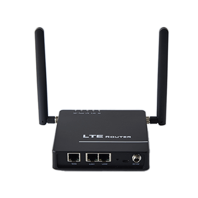
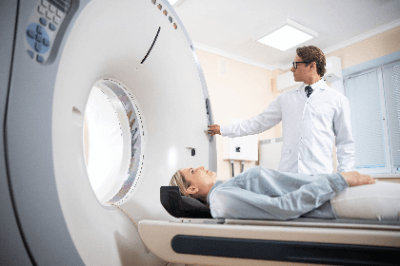
There are two main types of X-ray CT systems: medical and industrial.

Medical X-ray CT machines can examine bones, muscles, blood vessels, and other tissues from the head to the feet, as well as internal organs.

Uses of X-Ray CT Machines

There are two main types of X-ray CT machines: medical and industrial. They are explained in the following order. 

1. Medical X-Ray CT Machines

Medical X-ray CT machines detect X-rays transmitted through the human body to obtain information on the inside of the human body, and are used to determine medical conditions. There are two types of medical X-ray CT Machine: simple CT, which observes the human body as it is, and contrast-enhanced CT, in which a contrast agent is injected into the blood vessels for observation.

2. Industrial X-Ray CT Machines

Industrial X-ray CT machines are widely used in nondestructive inspection of materials, and such industrial X-ray CT machines are called “observation CT”. Examples of nondestructive inspection include shape evaluation and defect investigation of semiconductor packages, internal structure evaluation of tablets, and shape and fiber orientation evaluation of carbon fiber reinforced plastics.

In recent years, many industrial X-ray CT machines have also been developed for measurement purposes. Like CT for observation, CT for measurement enables nondestructive inspection, size measurement, and data analysis using CAD.

The “CT for measurement” enables full acquisition of the three-dimensional shape of the object, high-precision shape measurement, and high-speed inspection and measurement.

Principle of X-Ray CT Machines

There are two types of X-ray CT machine: medical and industrial. Both systems irradiate an object with X-rays from all directions in 360 degrees to examine the transmitted and absorbed X-rays, but the imaging methods used in medical and industrial applications are different.

1. Medical X-Ray CT Machines

A medical X-ray CT machine is characterized by a doughnut-shaped gantry and a bed that moves slowly through the center hole of the gantry while a human body is lying in the center hole of the gantry. Inside the gantry, an X-ray tube that irradiates X-rays and a detector that detects X-rays irradiated from the X-ray tube is placed across the center hole.

When a human body on a bed enters the center hole of the gantry, some of the X-rays emitted from the X-ray tube are absorbed by the human body, and the rest are transmitted and detected by the detector. At this time, the gantry rotates around the bed, irradiating X-rays from 360 degrees and detecting the transmitted X-rays.

The gantry then rotates around the bed, irradiating X-rays from 360 degrees and detecting the X-rays transmitted through the gantry. Helical scan is commonly used in this medical X-ray CT machine.

Helical scan is an imaging method in which the bed moves slowly through the center hole of the gantry while continuously irradiating and detecting X-rays. This produces a series of horizontally sliced images of the human body in the longitudinal direction in the direction of height. 

2. Industrial X-Ray CT Machines

Unlike medical X-ray CT machine, industrial X-Ray CT Machine is characterized by the fact that the material under investigation rotates instead of the X-ray tube and detector being fixed. There are two types of industrial X-Ray CT machines: the horizontal irradiation type and the vertical irradiation type.

The horizontal irradiation type has the X-ray tube, material, and detector arranged horizontally, while the vertical irradiation type has them arranged vertically. The appropriate type is selected according to the material to be investigated and the location to be investigated.

Other Information on X-Ray CT Machines

1. Multi-Slice Medical X-Ray CT Machines

Medical X-ray CT machines include multi-slice medical X-ray CT machines with multiple rows of detectors arranged in the direction of bed movement.

In this single-slice X-ray CT machine, the detectors are arranged in the direction perpendicular to the direction of bed movement, i.e., transversely for humans, and are distributed in a single row in the direction of bed movement. Therefore, when the gantry makes one rotation, only one cross-sectional view is constructed.

In contrast, the multi-slice medical X-ray CT machine has multiple rows of detectors distributed in the direction of bed movement, enabling acquisition of multiple cross-sectional views with a single rotation of the gantry. This enables imaging in a short time and reduces the burden on the human body. 3D images can also be constructed by combining this with helical scanning. 

2. 3D Image Processing Methods for X-Ray CT Machines

The following three types of 3D image processing methods are used in X-ray CT machine technology.

Multi-Panel Reconstruction (MPR)
Multi-Panel Reconstruction (MPR) is characterized by its ability to construct images from three-dimensional data in the coronal and sagittal cross sections, which are cross sections in the direction of the human height, in addition to the transverse cross section of the human body. This method is the most used in current CT 3D processing.

Maximum Image Projection (MIP)
In the maximum intensity projection (MIP) method, an arbitrary viewpoint is set for the three-dimensional data. The maximum value along the path between the viewpoint and the projection plane is then projected onto a two-dimensional surface.

It is characterized by its ability to minimize the effect of image noise and to output images with good contrast, even if they are low-contrast images. However, since values other than the maximum value are not reflected in the image, several angles of observation are required if the front and rear positions are to be determined correctly.

Volume Rendering (VR)
The volume rendering method (VR) sets the upper and lower limits of CT values for the area of interest. The image is then constructed by adding parameters corresponding to opacity to the set range and performing shading processing. This method is suitable for 3D images of blood vessels, etc.

カテゴリー
category_usa

Stainless Steel Grating

What Is a Stainless Steel Grating?

Stainless Steel Grating

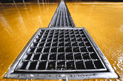
Stainless Steel Grating is a steel grating product used for floor surfaces.

It is made of stainless steel, and is generally used for floor ventilation, water drainage, and slip prevention, for example, in factories and public places.

Uses of Stainless Steel Grating

Common uses of grating are as follows:

1. Drainage

Gratings are used for efficient drainage of water. For example, they are found in bathhouses, around swimming pools, in stormwater runoff areas, and in drainage channels. The grating structure allows water to pass through, preventing puddling and helping to reduce flood damage.

2. Ventilation

Used for floors in industrial facilities, machine rooms, subway stations, etc. Where ventilation is required, grating ensures air flow and supports ventilation.

3. Anti-slip

Gratings are used to improve safety when walking or moving vehicles in slippery areas. They are especially common in wet environments or where liquids may spill onto the floor. They are commonly found in factories, warehouses, ship decks, pedestrian bridges, etc.

4. Visual Effects

Gratings are sometimes used in locations with visual effects. Gratings made of transparent materials are sometimes used in underground station platforms and elevated walkways to visually connect the visible space below. This ensures brightness and reduces a sense of claustrophobia.

5. Design Elements

Gratings are also used as design elements in buildings and public areas. They serve as a beautiful design or decorative element in flooring materials. They may be employed as part of landscape design or building exteriors.

Principle of Stainless Steel Grating

The principles of grating are based on the principles of drainage and ventilation. Gratings are structures that help water and other liquids pass through the floor surface and drain downward. To accomplish this, grating has grooves or holes.

This keeps water from pooling on the floor surface. Additionally, some grates may be sloped to allow water to flow more easily downward. Gratings are also products used in areas where ventilation is needed; they have an open structure that allows ambient air to pass under the floor.

Features of Stainless Steel Grating

1. Corrosion Resistance

Stainless steel is a corrosion-resistant material. It has better corrosion resistance than steel grating floors in grating floors used in water, humid environments, chemicals, and salty environments. This property provides long-lasting durability and low maintenance. 

2. Load-Bearing Capacity

Stainless steel is a tough material and may have higher load-bearing capacity than non-stainless steel grating. It performs well on platforms subjected to heavy machinery and loads, and in areas subject to frequent pedestrian and vehicular traffic.

3. Hygienic

Stainless steel is a hygienic material because it has a smooth surface and is resistant to dirt and bacteria. It is suitable for grating used in food processing facilities, medical institutions, and other locations where environmental cleanliness is required.

4. Appearance and Design

Stainless steel has a beautiful appearance and is suitable for modern design. It can provide functionality while maintaining a beautiful appearance, especially in buildings and public places.

Types of Stainless Steel Grating

The main types of grating are as follows:

1. Steel Grating

Welded steel grating, durable and load-bearing. Used in factories, warehouses, platforms, etc. Stainless Steel Grating is also included here.

2. Aluminum Grating

This grating is lightweight, corrosion-resistant, and has excellent ventilation properties. It is sometimes used in outdoor facilities and places where light loads are applied.

3. FRP Grating

FRP grating is a plastic grating reinforced with glass fiber. Lightweight, corrosion-resistant, and electrically insulating, it is sometimes used in chemical plants and electronic facilities.

4. Wood Grating

This grating is made of wood. They have a beautiful appearance and are found in some parks, gardens, and promenades.

5. Plastic Grating

Lightweight, chemical-resistant, and electrically insulating, it is often used around chemical facilities and electronic equipment. It is also sometimes used around swimming pools.

How to Select Stainless Steel Grating

Stainless steel grating is selected when it is necessary to withstand corrosion, such as in coastal areas, or when it is necessary to maintain the beauty and appearance of the landscape by gloss. In addition, stainless steel grating should be selected in terms of load capacity, grating width, and anti-slip properties.

The appropriate load should be selected according to the location and purpose of use. It is important to select an appropriate load, because the grating may be deformed or damaged if the load is exceeded.

In addition, the width of the grating can be varied to change the size of the passing object. Fine grating widths are used in places where there is a risk of wheels falling off, such as carts, etc. The size and roughness of the grating are specified according to the groove width used in JIS standards, etc., so it can be used in accordance with the groove regardless of the manufacturer.

It is important to select a grating with high anti-slip properties for outdoor and humid places. Slip-proof grating can be prevented by changing the shape of the surface.

カテゴリー
category_usa

MLSS Meter

What Is an MLSS Meter?

MLSS Meters

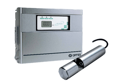
An MLSS Meter is a device that measures the concentration of suspended solids (SS) in a liquid.

It is mainly used in the field of water treatment. In sewage treatment, the activated sludge method, which is a biological treatment using activated sludge, is generally used.

MLSS stands for “Mixed Liquor Suspended Solids” and refers to the suspended solids in the mixture of sewage and return sludge that flows into the treatment system.

Usage of MLSS Meters

MLSS Meter is used in the water treatment field to control the function of the activated sludge process. MLSS concentration is an important maintenance standard for activated sludge treatment facilities.

The activated sludge method uses bacteria that use organic matter as a nutrient source. If there is too much organic matter in relation to the amount of microorganisms, not only will the organic matter not be fully decomposed, but the bacteria will also divide excessively and the settling of flocs will deteriorate. Conversely, if there is not enough organic matter, it is known that the floc will collapse due to self-digestion, thus worsening the settling ability of the floc.

By measuring MLSS concentration, which is an indicator of microbial content, and managing it in accordance with the amount of organic matter, the treatment facility can function at its best.

Principle of MLSS Meters

MLSS Meter is a device to measure MLSS concentration by utilizing the light scattering phenomenon. When light is incident on a liquid containing MLSS, the light is scattered by MLSS. As the MLSS concentration increases, the amount of transmitted light decreases, while the amount of scattered light increases.

For this reason, the MLSS concentration can be determined by knowing the amount of transmitted light, scattered light, or both. Most MLSS meters on the market use either the transmitted light measurement method or the scattered light measurement method.

1. Transmitted Light Measurement Method

In the transmitted light measurement method, light from a light source lamp is incident on the MLSS-containing liquid introduced into the measurement cell, and transmitted light is measured. Since fluctuations in the amount of incident light can cause measurement errors, the system is designed to maintain a constant amount of light from the light source by installing a light receiver.

2. Scattered Light Measurement Method

In the scattered light measurement method, light is incident directly on the liquid to be measured, and the scattered light is measured by the MLSS. As with the transmitted light measurement method, fluctuations in the amount of incident light can cause errors. Therefore, a double scattered light comparison method using two photodetectors is used.

How to Select an MLSS Meters

1. Measurement Principle

There are various measurement principles of MLSS meters, such as the membrane filter method and the solids rotation method. It is important to select the appropriate principle according to the purpose and application. Select the best one considering accuracy, reproducibility, ease of operation, and other factors. 

2. Measurement Range

Select an MLSS Meter with a measurement range suitable for the MLSS range of the target water treatment process, which typically ranges from a few mg/L to several g/L. Ensure that the measurement range matches the requirements of your process. 

3. Accuracy and Reliability

The accuracy and reliability of MLSS meters are essential for accurate data collection and process evaluation. Selecting an MLSS Meter with high accuracy and reliability will ensure accurate data. In addition, selecting a highly reliable manufacturer and product will ensure stable measurements over a long period of time.

4. Ease of Operation and Maintenance

It is important to select an MLSS Meter that is simple to operate and easy to use. Selecting an MLSS Meter that can be easily calibrated and maintained on a regular basis will help maintain accurate measurements and stable performance.

Other Information on MLSS Meters

1. How to Use the MLSS Meter

General measurement procedure of the MLSS Meter:

1. Turn on the power.
2. Place the probe in the test water and submerge it until the sensor is submerged.
3. Hold the reading steady, and when it stabilizes, read the indicated value. The indicated value varies from MLSS Meter to MLSS Meter, so multiply the indicated value by a constant or value according to your needs.
Some MLSS Meters have a wobble mitigation function for the indicated value.

How to measure the interface:

  1. Turn on the power.
  2. Place the probe in the test water and submerge it until the sensor is submerged.
  3. Read the depth indication at the point where the MLSS measurement value changes significantly.

Interface measurement method using the interface lamp

  1. Set the concentration at which the interface is to be determined.
  2. Slowly submerge the probe in the test water.
  3. Read the indicated value of the depth when the interface lamp lights up. 

Calibration of the Mlss Meter

When performing calibration of the MLSS Meter, follow the instructions below:

  • When the detector is replaced.
  • When the prism assembly is replaced.
  • When the measurement error of the MLSS Meter exceeds the permissible value.
  • After periodic maintenance.

In addition, there are two methods of calibration as follows.

Actual solution calibration method
This is a calibration method in which the measured liquid is manually analyzed or measured with a reference instrument and adjusted to the obtained value. This calibration method is necessary for accurate MLSS measurements.

There are three calibration procedures for this method:

  1. Since the MLSS value varies depending on the nature and condition of the liquid being measured, a sample of the liquid to be measured is taken near 100% of the measurement range, and the point at which 100% is reached is matched.
  2. Dilute the liquid used for calibration of the 100% point and adjust the 50% point.
  3. Adjust the 0% point using tap water.

Simple Calibration Method
The simple calibration method uses a set of calibration plates. The calibration plate is attached to the detector immediately after the above actual solution calibration method is performed. The MLSS value at that time is written on the calibration plate.

The next calibration is performed to match the value recorded on the calibration plate. This calibration method is employed during routine maintenance. The calibration plate with the values already entered cannot be transferred to another MLSS Meter.

カテゴリー
category_usa

M2M Router

What Is an M2M Router?

M2M Routers

An M2M (machine to machine) router is a device that acts as a relay between devices and servers when various data collected by sensor devices at the end of the line are collected on servers for data processing.

For example, when multiple water level sensors are installed at multiple observation points to monitor the water levels of rivers and other bodies of water constantly, it is necessary to install wireless interfaces such as 3G and LTE to send data from the sensor devices to the server. As a result, each sensor device becomes very expensive.

M2M routers must be able to withstand a wide operating temperature range and be dustproof, as they will be used in harsh environmental conditions. 

M2M Router Applications

M2M routers are used in a wide range of applications, including surveillance, equipment control in factories, disaster prevention, distribution warehouses, and agriculture.

1. Around and Inside Buildings

For surveillance applications, multiple cameras are installed around buildings in the city, condominiums, supermarkets, and even train stations, mainly for crime prevention purposes.

2. Factories

In factories, cameras are used to control various types of equipment, or to count and monitor the production status and number of products produced on production lines.

3. Logistics Warehouse

In distribution warehouses, M2M routers are used to check the availability, quantity, and management of inventory items.

Principle of M2M Routers

The basic operation of a system using an M2M Router is as follows:

1. Receive Data From Sensor Devices

An example of a surveillance application is a surveillance camera system installed in a city. Here, the surveillance camera serves as the sensor device, which has a built-in wireless interface such as Wi-Fi, and sends the camera images to the M2M router. 

2. M2M Router Internal Processing

The M2M router receives camera images from multiple locations, compresses the image data and processes it into a data format that can be easily processed by the server side, along with data indicating image attributes. It then encrypts and protects the data, and transmits it to the server over 3G, LTE, or other lines.

After processing the data sent from the M2M router as necessary, the data is made ready for analysis and displayed on a display

3. Receiving Data From the Server

The above is the flow of data transfer from the sensor device to the server side, but there is also a reverse direction. For example, when a suspicious person is found in the displayed surveillance image and further tracking is required.

Here, the surveillance camera on one of the sensor devices is oriented to track the suspicious person. To do this, the server will issue a “change direction” command to this surveillance camera. The command arrives at the M2M server via a line such as 3G or LTE.

Upon receiving this command, the M2M server identifies the camera(s) from which the server received the command from among multiple cameras, and forwards the command only to the camera(s) to which the command was sent. In this case, the commands are generally converted into commands that can be interpreted by the surveillance cameras.

When the camera receives the command sent from the server, it controls itself and changes the direction of the camera. In this way, the sensor device and the server communicate with each other via the M2M router.

Other Information on M2M Routers

1. Communication Protocols of M2M Router

An example of M2M communication is communication via the Internet using wireless communication means such as GSM, 3G, and LTE. These communication methods were originally used for human-to-human communication using mobile wireless communication networks. Later, they began to be used with the intention of expanding the market to include device-to-device communications.

M2M communications for device-to-device communications can be local, closed or wired communications in addition to the above communication methods. Considering cost and communication performance, communication between devices is realized by appropriately combining these various communication means.

2. Difference From IoT

IoT stands for “Internet of Things” and refers to the various objects in society that are connected to the Internet and can communicate with each other, etc. IoT is basically considered consisting of four components: data collection, data storage, data analysis, problem solving, and value creation. The difference between IoT and M2M is that IoT is connected to M2M.

The difference between IoT and M2M is in what it connects and how it connects: M2M refers to communication via the Internet, as well as direct machine-to-machine communication. On the other hand, IoT connects not only to machines but also to other devices and sometimes even to people.

Also, while the purpose of IoT is to collect and utilize information, the purpose of M2M is to collect information from and control machines. M2M is suitable when accurate information needs to be collected by sensors.

カテゴリー
category_usa

FX Gutter

What Are FX Gutters?

FX gutters are more rounded in shape than regular gutters and are highly stable. They are lighter than regular gutters, making them easier to handle and install. They also have a better fit, which reduces lid rattling and noise when vehicles pass by.

The load strength and flow rate are comparable to those of normal gutters, and the amount of excess soil can be reduced, resulting in environmental friendliness and cost reduction.

In addition, FX gutters are slimmer than conventional gutters, allowing the width of sidewalks to be extended by up to 20 cm.

Applications of FX Gutters

FX gutters are used in the same applications as conventional gutters, such as on forest roads and roads used for daily life, etc. Since FX gutters have less rattling caused by vehicle traffic, they can reduce noise problems at night and in urban areas. Because FX gutters are light and easy to install, they can be installed in less time than conventional gutters and are often used in high-traffic areas.

Variations are available for entrances and exits, corners, mud boxes, and sumps.

Principle of FX Gutters

Conventional gutters have a structure where the lid is simply placed horizontally, which makes them less stable when vehicles pass by, etc. FX gutters are processed into a shape called the “triple support function,” which improves stability.

The lid receiving portion of the FX gutter’s gutter body is in contact with the R-plane, and the lower part of the lid is in contact with the V-plane; the R-plane and V-plane make linear contact to absorb the impact of the loading load on the lid and reduce lid rattling and bounce. Fit points are also made horizontally on the sides of the lid to integrate the product and prevent misalignment.

In addition, the flat sides of the gutter allow for construction in close contact with nearby structures. This allows for sufficient compaction, thus preventing pavement settlement.

Both the gutters and lids are lighter, with the lid of a 300-width conventional gutter weighing about 46 kg, while the FX gutter weighs only 29 kg.

The amount of excavation is less than conventional gutters, reducing excavation time and the cost of overburden disposal.

FX gutters can also be fitted with a filter for drainage.

カテゴリー
category_usa

FRP Drain

What Is an FRP Drain?

FRP drains are drains made of a “fiber-reinforced plastic” called FRP. There are vertical drains and horizontal drains. FRP drains are often used because they are lightweight, strong, waterproof, and durable.

FRP is used as a waterproof layer and FRP drain parts are also seamless and highly effective in preventing water leakage.

Uses of FRP Drains

FRP drains are used on balconies and verandas on the rooftops of ordinary houses and buildings. If the flooring material is FRP waterproofed, FRP drains are especially effective in preventing leakage. Inexpensive non-FRP drains often cause separation from the waterproof layer, but FRP drains are compatible with the FRP waterproof layer and provide a good seal.

FRP drains are installed with nails or caulking. Make sure they are tightly sealed to prevent air from entering the gap, and caulk them again after installation to improve waterproofing.

Principle of FRP Drains

The FRP in FRP drain refers to fiber-reinforced plastic, a composite material made of unsaturated polyester and glass fiber, which is highly waterproof and durable.

FRP drains consist of an FRP flange and a vinyl chloride body. The shape of the flange differs between the vertical and horizontal types, and using the same FRP drain for the FRP waterproofed floor and drainage prevents the drain from peeling off from the waterproof layer, thereby preventing leakage. For this reason, FRP drains are used together with FRP waterproofing on residential balconies, rooftops, swimming pools, etc.

Horizontal FRP drains make holes in the horizontal wall instead of the floor, allowing wider use of the floor. Drainage efficiency is lower than that of vertical drains, but they are easier to install and replace because they are easier to prepare the substrate.

Vertical FRP drains are difficult to process because holes are drilled in the floor, but they are characterized by their high drainage efficiency. Even if the waterproof layer and drain should separate, water will not leak if it does not flow back.

FRP drains for renovation have a large flange and are easy to process.

カテゴリー
category_usa

CMOS Camera Module

What Is a CMOS Camera Module?

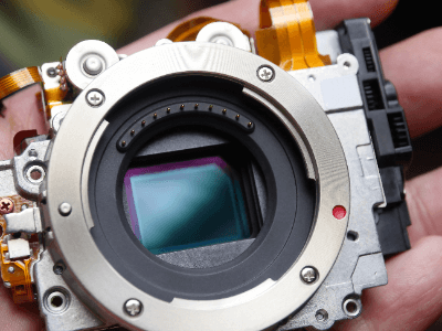
CMOS Camera ModulesA CMOS camera module is a camera equipped with a CMOS image sensor.
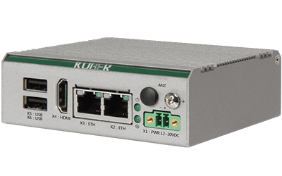
Specifically, it performs image recognition and application detection. Advances in signal processing and other technologies have made it possible to reproduce rich colors and reduce power consumption. In addition, modules are miniaturized and can be customized for various applications.

With AI and 5G technologies flourishing in recent years, the market size of CMOS Camera Modules is increasing every year.

Applications of CMOS Camera Modules

CMOS camera modules are small and can be customized for various applications. The main applications are various, including automotive, PC/smartphone, and factory/residential applications.

Products are used in various automotive cameras, accident recorders, intercoms, surveillance cameras, barcode scanners and various detection devices, making them ideal devices for image input devices. They are also used in PC cameras and wearable cameras to enable work-at-home and remote web conferencing.

Principle of CMOS Camera Modules

A CMOS camera module converts light entering through the lens into an electrical signal to acquire an image. There are two main parts: the sensor part, which performs everything from photoelectric conversion to digitization, and the signal processing part, which performs image processing to produce an image that is visible to the human eye.

First, light concentrated through the lens is converted into electrical signals by the CMOS image sensor and integrated circuits. Then, the internal image processor converts them into digital image signals. This digital signal is then processed by a processor called a DSP and output as image data.

The lens, CMOS sensor, and DSP are very important components that determine the quality of the camera.

Structure of a CMOS Camera Module

A CMOS camera module consists of the following components: optics, imaging sensor, and a signal processor. The components are mainly the lens, CMOS image sensor, lens, and substrate. The materials used are silicon, glass, metal, and various other materials.

Other Information on CMOS Camera Module

1. What Is a CMOS Image Sensor?

Image sensors used in digital cameras are either CCD (charge-coupled device) image sensors or CMOS (complementary metal oxide semiconductor) image sensors. Both share the use of photodiodes, but differ in their manufacturing processes and signal amplification methods.

A CCD is a sensor that applies voltages to its electrodes in sequence, transfers the charge in a relay fashion, and finally amplifies the signal; a CMOS image sensor has a switch consisting of a photodiode and a CMOS transistor for each pixel, and amplifies the signal for each pixel.

The switches are attached to the photodiodes arranged in a grid, and by switching the switches and reading out one after another pixel by pixel, high-speed charge transfer can be achieved.

2. Features of CMOS Image Sensors

CMOS image sensors have the advantage of lower readout noise than CCDs because charge signals are amplified in each cell. In addition, it uses general-purpose semiconductor manufacturing equipment, resulting in lower manufacturing costs.

Compared to CCDs, CMOS image sensors have the advantage of smaller power consumption due to the smaller element size and are less prone to smear and blooming.

3. CMOS Image Sensor Structure

An image sensor consists of, from the surface, microlenses, camera filters, photodiodes, and transfer circuits. Light collected by the microlens is classified by color using a color filter. The principle is that the photodiode then performs optical conversion, converts the light into an electrical charge, and then transfers the electrical signal.

カテゴリー
category_usa

Mini PC

What Is a Mini PC?

Mini PCs

A mini PC, as the name suggests, is a type of computer shaped like a box.

It is attractive because of its small size and high performance. It can be installed in a space-saving manner and is more durable than a typical desktop PC, protecting the PC interior from the external environment, such as vibration, heat, and dust. This makes it ideal for industrial applications and use in harsh environments.

Performance is another area where mini PCs excel. They can be equipped with modern high-performance CPUs, memory, SSDs, etc., and can be designed in the optimal configuration for each application.

These characteristics make mini PCs an important choice for building or updating your IT infrastructure. The adoption of mini PCs, which are compact, robust, and high-performance, can greatly contribute to the efficiency and optimization of an organization.

Uses of Mini Pcs

Mini PCs, which are particularly robust and high-performance, demonstrate their capabilities in a wide range of business applications. Here are some examples, especially in the areas of factory automation, visual inspection, production control, and monitoring systems.

1. Factory Automation

The control and management of automated lines requires precise and fast computational processing, and a mini PC’s high performance and robustness meet these requirements, allowing factory automation to proceed smoothly.

The mini PC’s durability guarantees stable performance even in harsh factory environments, such as vibration, temperature changes, and dust. 

2. Appearance Inspection

The mini PC’s high-speed image processing and analysis capabilities make it ideal for visual inspection of production lines; with Mini PC, minute defects in products can be detected in real time to improve quality control.

3. Production Control

Production control requires real-time processing and analysis of large amounts of data, and a mini PC’s powerful computing power makes this possible, providing powerful support for operations such as production volume optimization, inventory control, and delivery schedule optimization.

4. Monitoring System

A mini PC’s compact size and high performance make it ideal for video processing, analysis, and recording in surveillance systems. Its robustness also guarantees stable operation over long periods of time and allows for a quick response to any eventuality.

As described above, mini PCs can take advantage of their high performance and durability to demonstrate their capabilities in a variety of business domains. As these uses indicate, mini PC plays an important role in a wide range of industries.

Characteristics of Mini PCs

Most mini PCs are designed to be installed in a cabinet or rack. With a variety of interfaces, Mini PCs can be connected to displays or terminals in one or more separate locations.

Some can be connected to existing PCs, some are fanless, some are dustproof and waterproof, and some are made of antimicrobial plastic for medical applications. Thus, mini PCs (industrial PCs) have advantages over consumer PCs in terms of long-term stable supply of parts, high reliability of each part, and environmental resistance, such as the ability to be used in areas subject to vibration and dust.

On the other hand, the disadvantages are higher price and longer delivery time compared to consumer PCs.

How to Select a Mini PC

When selecting a mini PC, it is necessary to consider various factors, such as performance, durability, and cost performance according to the intended use.

1. Performance

The performance required depends on the intended use of a mini PC. For example, if high-speed data processing or graphics processing is required, a high-performance CPU or GPU and memory capacity are important. 

2. Durability and Environmental Friendliness

Durability and environmental compatibility are also important selection criteria for PCs, especially when used for industrial applications. For example, specifications such as dust and water resistance, high/low temperature resistance, and vibration resistance are essential for use in specific environments.

3. Expandability

It is also important to consider the expandability of a mini PC in preparation for future changes in needs. For example, check for additional memory slots and storage, or the type and number of ports.

4. Cost Performance

Finally, cost performance is another important selection criterion. In addition to purchase price, energy consumption and maintenance costs are also included in the total cost of ownership, so it is important to take these factors into account when selecting the most appropriate mini PC.