カテゴリー
category_usa

Rough Guide

What Is a Rough Guide?

A rough guide is a jig component used in machine tools, assembly machines, inspection machines, etc., to fix products in place. Broadly, it serves to preliminarily position a product to a certain extent before precise positioning is done.

Rough guides are primarily used when a worker, rather than a robot, sets a product on a jig. Their use significantly speeds up the precision positioning process by automatically fixing the product in a specific position.

Uses of Rough Guides

Examples of rough guide applications include:

  1. Rough Positioning According to the Workpiece’s External Shape
    A block or similar object is placed on a jig to align it with the workpiece’s shape. The mounting holes of the block are often elongated or several millimeters larger than the mounting bolts, allowing for easy adjustment during actual work.
  2. Rough Positioning Using a Thin Pin in a Material Hole or Workpiece Hole
    While precise positioning typically uses machined holes with controlled dimensions, rough guides can utilize material holes by inserting a pin a few millimeters smaller.

Features of Rough Guides

Rough guides come in various types, each with distinct features. For instance:

  1. L-Shaped Block Rough Guides
    These are used to guide the corners of a product. A gap of several millimeters is maintained between the product corner and the guide. Typically, two guides are positioned diagonally to phase the product correctly. The guiding part of the rough guide is usually inclined at about 60 degrees, automatically directing the product to the proper position as it follows the slope.
  2. Pin-Type Rough Guides
    Multiple pins, a few millimeters in diameter, are inserted into the material or processing holes of the product to roughly guide its position and phase. To protect the interior of the product holes, the tips of the pins may be rounded or made of resin. However, resin pins can be susceptible to damage from iron scraps, so the usage environment should be considered.
カテゴリー
category_usa

Image Processing Lighting

What Is Image Processing Lighting?

Image Processing Lighting

Image processing lighting refers to lighting systems used in image processing to enhance the visibility and detail of the object being photographed and its environment.

Lighting is crucial in image processing, where images are captured and analyzed for various purposes. Proper lighting significantly influences image quality, facilitating the extraction of detailed information about the photographed object. Uniform illumination, for instance, simplifies the process of detail extraction.

This type of lighting also plays a key role in defect inspection and quality control by accentuating specific features or flaws, making them more visible.

However, selecting suitable lighting for both the subject and the environment is essential. Inappropriate lighting can negatively impact image quality and the accuracy of the analysis.

Applications of Image Processing Lighting

Image processing lighting finds its application in diverse areas, including:

1. Inspection

Used in industrial quality assurance, image processing lighting helps detect defects in product surfaces while manufacturing electronic devices and other products.

2. Automatic Recognition Systems

In robotics and automation, this lighting enhances the accuracy of systems like barcode and QR code readers, and face recognition technologies.

3. Medical Imaging

Crucial in medical imaging methods like X-rays, CT scans, and MRIs, proper lighting ensures enhanced image contrast and clearer visualization of lesions for accurate diagnosis.

Principles of Image Processing Lighting

The primary goal of image processing lighting is to illuminate the subject uniformly, with appropriate color temperature and directionality, ensuring high-quality image capture.

Uniform illumination minimizes shadows and reflections, enhancing image contrast. The color temperature of the light source influences the image’s hue, while consistent lighting is crucial for accurate color reproduction. Directional lighting highlights the surface features of the subject, aiding in detailed analysis.

How to Select Image Processing Lighting

Key considerations when selecting image processing lighting include:

1. Object Characteristics

The lighting choice should complement the object’s color, shape, and surface texture. Some applications may require specific wavelengths or specialized lighting.

2. Power Requirements

Consider the power consumption and potential need for cooling in high-power lighting systems.

3. Lighting Stability

Stable lighting sources are essential for consistent image quality.

カテゴリー
category_usa

Flexstar Belt

What Is a Flexstar Belt?

A flexstar belt is a trade name for a type of flat belt. As a friction belt, it transmits power through the frictional force between pulleys and the belt. Constructed from special synthetic rubber, it boasts a thin profile, enabling high-speed use with small-diameter pulleys.

The design of a flexstar belt includes transverse shear reinforcement on the front side to increase rigidity perpendicular to the running direction, preventing vertical tearing. This structure also enhances bendability in the running direction, facilitating use with small pulley diameters.

The belt’s core wire, made of specially processed polyester cord, minimizes elongation and maximizes strength. The rubber portion, composed of synthetic or chloroprene rubber, offers exceptional abrasion, weather, and alcohol resistance, improving the coefficient of friction and extending the belt’s lifespan.

Uses of Flexstar Belts

Flexstar belts are extensively employed in various industrial, machine tool, and office automation equipment, capitalizing on their compact size and high-speed capabilities. They are prevalent in general industrial machinery like blowers, pumps, and compressors; textile machinery such as winders and weaving machines; machine tools including NC lathes and drilling machines; electrical devices like generators and electronic equipment; as well as in paper manufacturing machinery and various office automation devices.

Features of Flexstar Belts

Flexstar belts are characterized by their thin, flexible design, allowing for small pulley diameters and compact machinery. Their lightweight nature reduces the impact of centrifugal force, supporting high-speed operation up to about 60 m/s. The belt’s substantial transmission capacity enables narrower belt widths, while the simple pulley shapes facilitate easier machining. Uniform belt thickness ensures reduced vibration and smoother operation. The special synthetic rubber material of the belt provides excellent heat and oil resistance, and prevents static electricity generation.

Another notable feature is the belt’s minimal elongation, virtually eliminating the need for tension adjustments and tension pulleys. While belt transmission relies on friction between the pulley and belt, leading to some slippage, flexstar belts are suitable for applications where slippage loss is not a concern.

Smaller flexstar belts are produced using one-piece molding techniques, ensuring seamlessness for increased flexibility and bendability.

カテゴリー
category_usa

Electrical Circuit Component

What Is an Electrical Circuit Component?

Electrical Circuit Components

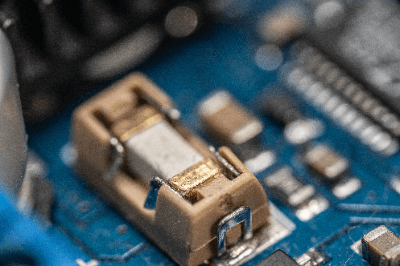
An electrical circuit component is a type of fuse designed for direct mounting on electronic circuit boards using surface mount technology.

These components serve as protection devices in electronic circuits. They protect against overcurrents and short circuits by interrupting the current flow when it exceeds a predetermined threshold, thus preventing damage to the circuit or device.

Being mechanical devices, these fuses are highly reliable and offer a long service life. Their compact size allows for high-level integration directly on the circuit board.

However, selecting the appropriate current rating and response time is crucial. An incorrect rating can result in accidental interruptions or inadequate protection if the circuit’s current exceeds the fuse’s capacity.

Applications of Electrical Circuit Component Fuses

Electrical circuit component fuses are used in various applications, playing a crucial role in circuit and device reliability by guarding against overcurrents and short circuits. Some common applications include:

1. Telecommunications Equipment

In telecommunications, where network and data transmission reliability is vital, these fuses safeguard communication circuits. For instance, they are used in network interfaces and data communication circuits to prevent surges and short circuits, ensuring data accuracy and network stability.

2. Automotive Components

In modern automobiles, these fuses protect sophisticated electronic control systems like engine control units and airbag control modules, contributing to vehicle safety and preventing electrical system damage in accidents.

3. Consumer Electronic Products

Commonly found in home appliances and consumer electronics, these fuses contribute to the stable, long-term operation of devices like televisions, refrigerators, computers, and smartphones by protecting them from overcurrents and malfunctions.

Principles of Electrical Circuit Component Fuses

These fuses operate on a simple principle: they blow when the current exceeds a certain threshold. Comprising a conductor made of metal foil or wire, they allow current to pass with minimal resistance under normal conditions. However, upon overheating due to overcurrent, the conductor melts, breaking the current path and interrupting the circuit power.

How to Select Electrical Circuit Component Fuses

When choosing these fuses, consider the following factors:

1. Mounting Method

Choose the appropriate package shape for the board’s design and size, considering options like chip fuses and leaded fuses.

2. Rated Current

Ensure the fuse’s rated current matches the circuit’s current flow. Exceeding this rating triggers the fuse to interrupt, protecting the circuit.

3. Rated Voltage

Select a fuse with a rated voltage that can safely interrupt the operating voltage of the circuit. Exceeding this voltage can lead to fuse failure and potential hazards.

4. Response Time

Match the fuse’s response time with the circuit’s requirements. Shorter response times provide quicker interruption in overcurrent situations but also increase the risk of false disconnections.

カテゴリー
category_usa

Corner Bracket

What Is a Corner Bracket?

A corner bracket is a component used to safeguard and reinforce the corners of panels.

These brackets are also employed to secure the corners of railings. Corner brackets serve diverse purposes, including mounting, positioning, and reinforcing panels and equipment, protecting corners, preventing stains, and averting injuries and damage caused by collisions with corners.

They are constructed from various materials such as aluminum, stainless steel, and other metals, as well as resin, and are designed with pre-drilled holes for installation based on the required dimensions.

Applications of Corner Brackets

Corner brackets find application in a wide range of scenarios. Some examples include:

1. Electrical and Electronic Equipment Mounting

Corner brackets are used to mount electrical and electronic equipment securely in corners. They are also used for installing security cameras in ceiling corners. Additionally, they serve to protect and reinforce the corners of panels like picture frames and poster frames.

2. Handrail Corner Joints

Corner brackets are commonly employed at the corners of indoor and outdoor handrails to enhance safety. They are also used to secure rubber gaskets attached to the corners of refrigeration equipment, contributing to waterproofing efforts. Moreover, corner brackets play a significant role in the building industry, including applications in doors, windows, fixtures, and construction materials.

In outdoor applications, materials like stainless steel and other corrosion-resistant metals are favored. Some of these brackets are referred to as reinforcement hardware and are used at the corners where braces are affixed. They are also commonly employed in foundations and beams, often playing a role in earthquake protection for buildings.

Principle of Corner Bracket

Corner brackets are versatile components used for various purposes, including protection, reinforcement, mounting, railing safety, restraining fittings, waterproofing, and outdoor line anchorage fittings.

1. General Use

In general applications, corner brackets are installed at the four corners of panels to connect the vertical and horizontal elements, increasing their structural integrity and providing protection. They are also employed to reinforce box-type equipment by attaching them as plates to the equipment’s corners.

Corner brackets are used in room corners to secure shelves, install surveillance cameras, and perform similar tasks. Given the challenges of installing corner brackets, their design often facilitates easy fixation.

For handrail installations, safety is enhanced by using fixing brackets capable of accommodating bends in corner brackets. Brackets that conceal the end of the handrail at the terminus further improve safety.

2. Special Use

Corner brackets serve specialized purposes, such as acting as outdoor wire pull brackets in electrical applications. This is particularly relevant when the height above ground level is insufficient for outdoor wire installation or when obstructions hinder access to pull-in points.

In large refrigerator and freezer doors, corner brackets are positioned at the four corners to suppress rubber gaskets and enhance waterproofing.

Types of Corner Brackets

Aluminum corner brackets can be broadly categorized into the following types: protruded, extruded, and multi-row groove brackets.

1. Protruded Brackets

Protruded brackets feature a protrusion on the mounting surface to prevent rotation. They are typically made from ADC12, an affordable material compared to extruded brackets of similar size. The protrusion acts as a detent during installation, enhancing workability. Various additional function brackets are available, including single-rib brackets, nut-retaining brackets, brackets with protrusions on one side, single-sided long-hole brackets, and brackets with covers, among others.

2. Extruded Brackets

Extruded brackets are manufactured using aluminum extrusion and are composed of A6N01SS-T5 material with an anodized surface. They exhibit an appealing appearance, are dust-resistant, and provide greater strength compared to brackets with protrusions. Various types of extruded brackets are available, each offering additional functions. These include thick brackets, eccentric brackets, unequal brackets, and connection brackets of different sizes.

3. Multi-Row Groove Brackets

Multi-row groove brackets are used in frame structures with multiple rows of grooves. Examples include projecting brackets for 2-row grooves, extruded brackets for 2-row grooves, extruded brackets for 3-row grooves, and extruded brackets for 4-row grooves.

カテゴリー
category_usa

High Voltage Converter

What Is a High Voltage Converter?

A high voltage converter is a device that converts high voltage currents, such as 200 V and 400 V, commonly used in industrial settings. A converter that changes AC current to DC current is known as an AC/DC converter, while a converter that modifies DC current levels is called a DC/DC converter. Most AC/DC converters utilize diodes like MOSFETs for converting AC to DC through switching, whereas DC/DC converters typically use resistors or other components to induce a voltage drop, thereby altering the voltage.

Uses of High Voltage Converters

High voltage converters are widely used in industries requiring high voltage power supplies. These converters are essential for powering industrial DC motors, converting power for industrial equipment from AC to DC, and reducing voltage to drive equipment at its rated current. When selecting high voltage converters, compatibility with the intended current and voltage, size, loss, insulation performance, and safety are critical considerations.

Principles of High Voltage Converters

The operating principles of high voltage converters vary between AC/DC and DC/DC types:

  • AC/DC High Voltage Converters
    An AC/DC high voltage converter typically includes an AC power connection terminal, a DC power supply terminal, and MOSFET diodes. These diodes are often arranged in a diamond-like configuration. The switching action of MOSFETs is utilized to convert AC current to DC. When AC current passes through the diamond-shaped diode arrangement, the positive current continues unaltered, while the negative current is switched to positive. This process effectively converts AC to DC.
  • DC/DC High Voltage Converters
    A DC/DC high voltage converter may include a resistor, a transistor, or a transformer. Resistors in the circuit create a voltage drop to reduce voltage levels. Transistors achieve voltage reduction by switching the current in a pulse-wave manner. Transformers, on the other hand, use the number of coil turns to cause a voltage drop or increase, depending on the design.
カテゴリー
category_usa

Pneumatic Gripper

What Is a Pneumatic Gripper?

A pneumatic gripper is a device that uses compressed air to grasp objects.

Specifically, they refer to mechanisms that securely hold or lift objects by controlling airflow and pressure. Pneumatic grippers do not make direct contact with the objects they hold, minimizing the risk of scratching or damage.

They are commonly employed for handling delicate products and materials and are versatile enough to grip objects of various shapes and sizes. By adjusting the material of the suction cups and gripping components, they can be customized for a wide range of applications. Furthermore, they offer precise control for accurate object positioning.

However, due to their strong gripping capabilities, pneumatic grippers can pose hazards to individuals and surrounding objects if operated incorrectly or in case of malfunctions. It is crucial to adhere to safety precautions and operational guidelines.

Pneumatic Gripper Applications

Pneumatic grippers find applications in diverse industries. Here are some examples:

1. Manufacturing Industry

In automotive manufacturing, pneumatic grippers are employed to handle various components such as engine parts and body parts. They excel in accurately positioning heavy or complex-shaped parts.

In electronic product assembly lines, pneumatic grippers are frequently used to manipulate circuit boards and small components.

2. Logistics and Warehouse Management

Distribution centers and warehouses utilize pneumatic grippers for pallet loading and handling container loads. Efficient picking operations can reduce labor time and enhance logistics processes.

3. Food Industry

Pneumatic grippers play a vital role in packaging delicate food products like cakes and chocolates. They enable high productivity while safeguarding product integrity.

In factory conveyance operations, pneumatic grippers efficiently manage cases and packaged food products.

Principle of Pneumatic Gripper

Pneumatic grippers rely on air pressure to grasp objects. They typically consist of flexible suction cups or grips and internal tubes or valves for air supply.

To secure an object, the pneumatic gripper applies the suction cups or grips to the object’s surface, often sealing the area around them to prevent air leakage.

Subsequently, air is delivered to the pneumatic gripper from an air compressor or another source, reaching the suction cups or grips through internal tubes. As air flows in, the pressure within the suction cups and grips increases.

This elevated pressure causes the suction cups and grips to firmly adhere to the object’s surface, allowing it to be held securely. When the object needs to be released, adjustments to the pneumatic gripper’s internal pressure release the grip, enabling object release.

How to Select an Air Pneumatic Gripper

Choosing the right air pneumatic gripper involves considering several critical factors. Here are some considerations:

1. Rubber Material

The choice of rubber material for the suction cups and gripping components should align with the characteristics of the objects being handled. For instance, durable hard rubber is advantageous when hardness and abrasion resistance are required.

Conversely, softer rubber may be preferred for delicate product handling.

2. Recommended Payload

Pneumatic grippers come with recommended maximum payload specifications. Determining the weight of the objects to be handled in advance allows for selecting the appropriate gripper based on payload capacity.

カテゴリー
category_usa

IGBT Gate Driver

What Is an IGBT Gate Driver?

An IGBT (insulated gate bipolar transistor) gate driver is an electrical circuit used to effectively operate a semiconductor device called an IGBT.

The main purpose of a gate driver is to provide an accurate signal to the gate terminal and control the switching operation. This results in efficient power conversion and control.

IGBT gate drivers can detect overcurrents and overvoltages, protecting the IGBTs. This overload detection enhances system safety and reliability.

They also incorporate circuits to control electromagnetic interference from high-speed switching, minimizing impact on peripheral devices.

Applications for IGBT Gate Drivers

IGBT gate drivers are essential in high-voltage and high-current applications. Major applications include:

1. Inverters

Inverters, which convert DC power to AC power, are crucial in renewable energy systems like solar and wind power generation. They transform generated DC power into a form suitable for household or industrial use.

Built into inverters, IGBT gate drivers control the IGBTs, enabling efficient power conversion. The drivers amplify IGBT gate signals and perform switching control at precise intervals for optimal power conversion.

2. Motor Control

Motor control systems, used in industrial motors and railroad vehicles, regulate motor speed and torque by controlling the power supply.

These systems deliver drive signals to motors, facilitating efficient operation. High-performance motor control demands rapid and precise switching, underscoring the importance of IGBT gate drivers.

3. Laser Drive

High-power and high-speed switching lasers, used in laser drive systems, require precise pulse control, achievable with IGBT gate drivers.

Principle of IGBT Gate Driver

The IGBT gate driver precisely controls IGBTs for switching operations. IGBTs need a high gate drive current, and this device amplifies the gate signal to supply the necessary current.

It also generates the appropriate drive pulses in response to control signals, managing the IGBTs’ on and off states. This optimizes switching speed and interval, ensuring efficient power control.

IGBTs require controlled dead time during switching to prevent simultaneous activation and potential short circuits. The IGBT gate driver manages this dead time for accurate switching.

Types of IGBT Gate Drivers

Different IGBT gate driver types meet various requirements. Common types include:

1. Single-Channel IGBT Gate Driver

Designed for a single IGBT control, this driver is ideal for applications like DC motor control and small power conversion devices.

2. Multi-Channel IGBT Gate Driver

This type controls multiple IGBTs simultaneously, suitable for applications requiring coordinated switching, such as 3-phase inverter control and high-performance motor control.

3. Isolated IGBT Gate Drivers

Isolated IGBT gate drivers provide significant input-output isolation, crucial in high-voltage applications for enhanced safety.

カテゴリー
category_usa

Circuit Board Heat Sink

What Is a Circuit Board Heat Sink?

Circuit Board Heat Sinks

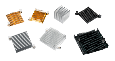
A circuit board heat sink is a cooling device attached to the circuit boards of electronic equipment and computers.

They are used to stabilize circuit operation by dissipating heat generated by electronic and electrical components mounted on printed circuit boards. Semiconductor components in various circuits tend to generate large amounts of heat when large drive power is required.

With the evolution of semiconductor processes, large-scale integrated circuits have been realized in extremely small sizes. In devices that realize such complex and advanced functions and performance, the amount of heat generated is also often large.

To reduce the amount of heat generated, various efforts are being made on the semiconductor device side to reduce power consumption. However, in most cases, heat sinks are required to maintain stable operation when used in various environments.

Circuit Board Heat Sink Applications

Circuit board heat sinks are cooling devices that are primarily used on electronic equipment and computer circuit boards. The following are some of their main uses:

1. CPU

The CPU is an important component responsible for computing and controlling the computer. A high-performance CPU performs many calculations and generates a lot of heat as a result. Overheating may cause performance degradation or damage.

Circuit board heat sinks are attached to the CPU to absorb the heat generated by the CPU. Heat exchange with the surrounding air is facilitated through the fins of the heat sink. This allows the CPU to maintain proper operating temperature and maximize performance.

2. GPU

The GPU is responsible for graphics-related tasks such as processing 3D graphics and decoding video. The GPU also often generates a lot of heat during graphics-intensive situations such as high-resolution games and video editing. Circuit board heat sinks are attached to the GPU to provide proper cooling and maintain high performance.

3. Power Electronics

Power electronics are electronic components that control or convert power. Inverters and motor drivers are examples.

These components handle high power and generate a large amount of heat. Circuit board heat sinks are attached to these components to provide efficient cooling. As a result, damage due to overheating can be prevented.

Principle of Circuit Board Heat Sink

The cooling principle of circuit board heat sinks is to effectively remove the heat generated on electronic device boards by using the processes of thermal conduction and thermal radiation.

1. Material and Shape

Circuit board heat sinks use aluminum, iron, and copper as their materials because of their good thermal conductivity. In addition, to increase the heat dissipation capacity of heat sinks, they are often designed to increase their surface area.

One example of such a device is to increase the surface area of a heat sink by placing many thin plates side by side on the surface of the heat sink with space between them. Products with many rod-like structures bonded to the surface are another way to increase surface area. In addition, when heat is to be dissipated efficiently, forced air cooling may be used to lower the ambient temperature.

2. Fixing Method

There are various ways to secure a heat sink to a PCB, including double-sided tape, pins, and clips. In some cases, double-sided thermally conductive tape is used to secure the heat sink.

In this method, double-sided adhesive tape with high thermal conductivity is placed between the heat sink and the heating element. This method is often used for small and lightweight heat sinks. Another method is to fix the heat sink and board with push pins.

The heat sink is held in place by spring tension. Another method is to secure the heat sink to the board with stepped screws, which makes it easy to replace the heatsink.

The Z-shaped clip method uses two anchors on the board and a Z-shaped wire clip to secure the heatsink in place. It is characterized by ease of attachment and removal.

Types of Circuit Board Heat Sinks

Circuit board heat sinks can be classified into two types depending on the cooling method: natural air cooling and forced air cooling.

1. Natural Air Cooling

Natural air cooling is a method that relies solely on heat dissipation from the heat sink. It is more advantageous in an open space with no enclosure. 

2. Forced Air Cooling

Forced air cooling is a cooling method that uses a fan. Forced-air cooling is more efficient when there is an enclosure. This system controls the air velocity inside the chassis by the size of the duct opening to dissipate heat.

In forced air cooling, too large a flow path reduces air velocity, and too small a flow path reduces airflow. To maintain proper air velocity and air volume, the minimum cross-sectional area of the flow path must be equal to or greater than the minimum cross-sectional area of the fan.

カテゴリー
category_usa

High Voltage Operation Amplifier

What Is a High Voltage Operation Amplifier?

A high voltage operation amplifier (HVOPA) is an operational amplifier capable of handling input and output voltages ranging from tens to hundreds of volts. They are utilized in scenarios where standard operational amplifiers are insufficient for managing high voltage ranges.

When deploying HVOPAs, it is crucial to design them with proper protection circuits, keeping in mind regulations and safety concerns associated with high voltages. Effective heat dissipation and thermal protection are also vital due to the potential for significant heat generation from high currents.

Uses of High Voltage Operation Amplifiers

High voltage operation amplifiers are chosen for applications where the voltage ranges exceed the capabilities of standard operational amplifiers. They are commonly found in piezo transducers in inkjet printers and ultrasonic transducers, automated test equipment for ICs and modules, and high-brightness laser diodes in optical detection and ranging systems.

Principles of High Voltage Operation Amplifiers

Functionally, HVOPAs operate similarly to standard operational amplifiers, amplifying the potential difference between the inverting and non-inverting inputs with high gain. They offer high input impedance, low output impedance, and the characteristic virtual short between input terminals.

To manage higher voltage ranges, standard op amps can be augmented with external components to increase output voltage, but this approach is complex and costly, involving numerous components and specific board layout considerations. This can lead to output distortion and reduced linearity due to variations in component characteristics and board layout.

The use of HVOPAs addresses these challenges. Some HVOPAs integrate ESD protection circuits, boost circuits for increased slew rate, circuits for stable capacitive and inductive load driving, and thermal and overcurrent protection circuits, all within a single IC package. This integration significantly simplifies the design process.