カテゴリー
category_usa

Piezoelectric Devices

What Is a Piezoelectric Device?

Piezoelectric Device

A piezoelectric device is a passive device that uses the piezoelectric and inverse piezoelectric effects that occur in dielectric materials such as quartz and quartz to control and detect micro-operation.

Because of their simple structure that does not require gears or motors for operation, piezoelectric elements are smaller than other micro-operation mechanism elements.

Uses of Piezoelectric Devices

Piezoelectric devices are mainly used in devices that detect and control minute movements for industrial applications.

For example, piezoelectric devices are used in vibrometers, where minute changes in force due to vibration are input to the piezoelectric devices as pressure, and the voltage generated in the piezoelectric devices under pressure is output to obtain a voltage value that is quantified as the magnitude of the vibration.

Piezoelectric drives are also used as drive systems accompanying stage movements of equipment such as microscopes and interferometers, which require precise movements.

Piezoelectric devices in such drive systems are called piezoelectric drivers or piezoelectric actuators, and multilayer actuators with multiple piezoelectric devices are also common components. In these devices, minute movements are achieved by applying minute pulse currents to the piezoelectric devices. Piezoelectric devices are suitable for situations that require high responsiveness and precise motion control.

1. Cooling of Electronic Equipment

While DC fans are often used to cool electronic devices such as PCs, cooling methods using piezoelectric devices have also been proposed.

Specifically, the inverse piezoelectric effect of piezoelectric devices is used to generate wind by vibrating a structure consisting of a piezoelectric device and a blade that generates wind.

This cooling method using piezoelectric devices produces less noise than DC fans and can be driven with less energy.

However, when the piezoelectric devices and blades are driven for long periods of time, the piezoelectric devices and blades may become disconnected, so a support plate is installed to disperse the stress on the structure.

2. Power Generation

Power generation systems using piezoelectric devices are also being developed.

For example, the Frontier Service Laboratory of the JR East Research and Development Center has been researching a “floor power generation system” and has been conducting demonstration tests at Tokyo Station since 2006.

Specifically, they are studying a system in which piezoelectric devices are laid out vertically, horizontally, and vertically like a floor, and electricity is generated by the piezoelectric effect when people walk on the floor.

The Frontier Service Laboratory of the JR East Research and Development Center estimates that the amount of electricity generated will be about 10 Wsec for the planned demonstration experiment in 2008-2009.

Thus, although the power generation capacity is not very high and the amount of electricity generated is not commensurate with the cost, and the piezoelectric devices are brittle materials with low durability. Research and development is currently being conducted by various companies and research institutes, and the theme is whether the system can generate electricity to a practical level.

3. Speakers

Speakers using piezoelectric devices have also been developed.

Principle of Piezoelectric Devices

The main material used in piezoelectric devices is piezoelectric ceramics. Piezoelectric materials have polarity, which is an electrical distortion inside the crystal.

Piezoelectric devices consist of a piezoelectric material sandwiched between positive and negative electrodes.

By applying voltage between the electrodes, pressure is applied to the piezoelectric material, which expands or contracts and displaces according to the magnitude of the voltage. This displacement is used as the driving force. In addition, it is also possible to detect voltage by applying pressure that deforms the piezoelectric devices in the opposite direction.

Under normal conditions, the crystal lattice in the piezoelectric body remains electrically stable by taking in ions from the atmosphere. However, when voltage is applied, the balance is easily upset and the polarity within the crystal changes, causing the crystal lattice itself to expand and contract in the direction indicated by the arrow, which is the displacement of the piezoelectric material.

In other words, the displacement of the piezoelectric material is at the level of a few microns at most due to strain deformation using the electronic polarity of the crystal lattice. The driving force of the piezoelectric element itself is generally as small as a few microns.

For this reason, a multilayer actuator consisting of multiple piezoelectric devices is used when an even larger driving force is required.

Other Information on Piezoelectric Devices

1. Principle of a Speaker Using Piezoelectric Devices

This is also based on the piezoelectric effect of piezoelectric devices. Vibrating members are placed in contact with the piezoelectric devices in the direction of expansion and contraction.

When voltage is applied to the piezoelectric devices, the piezoelectric devices expand and contract due to the piezoelectric effect, and the vibrations are transmitted to the vibrating member to reproduce sound.

2. Specific Products

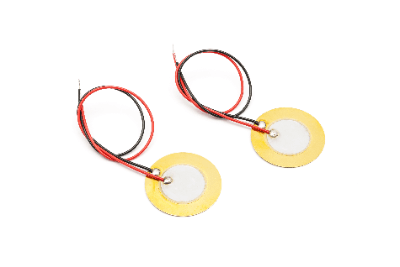
TDK Corporation sells a speaker called PiezoListen™ that uses piezoelectric devices.

The basic structure consists of piezoelectric devices coated with resin film and fitted with a frame and terminals for wiring.

By using piezoelectric devices capable of high displacement, this speaker has increased output in the low frequency range and achieved output over a wide sound range.

In addition, the use of fine ceramics for the piezoelectric devices has made the speaker smaller and thinner.

カテゴリー
category_usa

Vacuum Gauge

What Is a Vacuum Gauge?

Vacuum GaugeA vacuum gauge is a sensor used to measure the degree of vacuum in a given space.

Depending on its purpose, either a partial pressure vacuum gauge or a total pressure vacuum gauge is selected. There are also many measurement methods, and the range of vacuum that can be measured varies depending on the difference between them.

Examples of Vacuum Gauges Applications

Vacuum spaces are often used at manufacturing sites where high cleanliness is required, since there are infinitely few impurities, including moisture, in a vacuum space. Among these, vacuum gauges are installed in fluid circuits connected to chambers and quartz tubes that require vacuum reach control.

Vacuum gauges are often installed in plasma etching spaces in semiconductor manufacturing equipment and experimental facilities such as metallurgy and organic synthesis. Vacuum gauges are also used in situations where surface cleanliness is required, such as in ion beam equipment and evaporation equipment, where the surface of the object is processed.

Principle of Vacuum Gauges

There is a wide range of vacuum gauge types and measurement principles. Vacuum gauges successfully measure the momentum of a very small amount of gas molecules and convert it into gas density and degree of vacuum in space. The most commonly used vacuum gauges are the Pirani vacuum gauges.

The Pirani vacuum gauges are electrical resistance type vacuum gauges that calculate the electric current from the heat energy dissipated when the gas collides with the platinum wire through which the electric current flows. It calculates the pressure backward from that value. The micro-pressure is directly equivalent to the degree of vacuum.

How to Select Vacuum Gauges

There are many types of vacuum gauges, so it is necessary to select the vacuum gauge that best suits your purpose. It is important to fully understand the characteristics of each type of vacuum gauge, as they differ according to the type of application and measurement method.

In addition, since there are several types of vacuum gauges of various types, the selection should be made according to the vacuum level of the desired vacuum space to be measured. To guarantee the final vacuum attainment, one vacuum gauge is sufficient, but if you want to know the behavior of the vacuum pumping rate and other factors, multiple vacuum gauges must be installed.

Types of Vacuum Gauges

Vacuum gauges can be classified into several types in terms of application, measurement method, and measuring range.

1. By Application

Partial Pressure Vacuum Gauges
A partial pressure vacuum gauge is selected when the vacuum is to be measured only for individual gases, i.e., when two or more gases are mixed, the partial pressure is the pressure indicated by each gas.

It is used to analyze the quality of the vacuum since different types of gases have different properties at the same pressure. The most common partial pressure vacuum gauges are the mass spectrometer.

A mass spectrometer consists of an ion source, an analyzer, and a detection unit. By using an electric or magnetic field, it is possible to determine the pressure of each gas by observing only specific ions.

Total Pressure Vacuum Gauges
The total pressure vacuum gauges are selected when you simply want to measure the vacuum in a space. Since there are many types of vacuum gauges available depending on the measurement method, it is necessary to select the one that best suits your purpose.

2. Measurement Methods

There are three main types of measurement methods. There are three main types of measurement methods: methods that detect pressure itself, methods that use the transport phenomenon of gas, and methods that use the ionization phenomenon in gas.

Methods That Detect Pressure Itself
A U-tube vacuum gauge are differential pressure gauge that uses a glass U-tube, one end of which is evacuated to a vacuum, and the other end is sealed.

The U-shaped vacuum gauges are characterized by the fact that it is independent of the type of gas. The U-shaped vacuum gauges are unique in that it is independent of the type of gas, and is used as a calibration standard for other vacuum gauges because it allows absolute measurement of pressure.

Method Using Gas Transport Phenomena
Thermal conductivity vacuum gauges are vacuum gauges that utilize the transport phenomenon of gases. These vacuum gauges utilize the property that the thermal conductivity of a gas varies with pressure.

There are many types of thermal conductivity vacuum gauges, including Pirani vacuum gauges, thermistor vacuum gauges, and thermocouple vacuum gauges. The important point to note about thermal conduction vacuum gauges is that, at high vacuum, the effect of thermal radiation is greater than that of thermal conductivity. Therefore, thermal conduction vacuum gauges have the disadvantage that they cannot be used to measure high vacuum.

Method Using Ionization Phenomena in Gases
Penning vacuum gauges (cold cathode ionization vacuum gauges) and ion gauges (hot cathode ionization vacuum gauges) are vacuum gauges that use the ionization phenomenon of gases. Penning vacuum gauges use the discharge phenomenon in a vacuum to measure pressure. Although Penning vacuum gauges are highly durable, their sensitivity varies depending on the type of gas.

The advantage of the Penning vacuum gauges is that its circuit configuration is simple. On the other hand, the disadvantage is that penning discharges can be unstable, making it difficult to make very accurate measurements. Furthermore, if the surface is heavily contaminated, the amount of electrons emitted from the cathode is reduced and no discharge occurs, and it is difficult to initiate a discharge in a high vacuum condition.

3. Measurement Range

Pressure is divided into low vacuum, medium vacuum, high vacuum, ultra-high vacuum, etc., and the degree of vacuum measured depends on the type of vacuum gauge. Vacuum levels are classified into five categories according to the pressure range, as shown below. Pirani vacuum gauges can measure low to medium vacuum, and ionization vacuum gauges can measure medium to ultra-high vacuum.

  • Low vacuum: 105Pa to 102Pa
  • Medium vacuum: 102Pa to 10-1Pa
  • High vacuum: 10-1Pa to 10-5Pa
  • Ultra-high vacuum: -5Pa to 10-8Pa
  • Extremely high vacuum: 10-8Pa or less
カテゴリー
category_usa

UV Light Source

What Is a UV Light Source?

UV Light SourceA UV light source is a device that emits ultraviolet (UV) light.

In addition to the light source that generates the UV light, some commercially available UV light sources include a cooling system and an optical system that converts the UV light into a linear beam through a lens for easy use. The ultraviolet light emitted by each type differs.

There are three types of light sources, which are distinguished into “high-pressure mercury type” which emits ultraviolet rays with a wavelength of 365 nm (nanometers), “metal halide type” which emits ultraviolet rays from 200 to 400 nm, and “low-pressure mercury type lamps” that oscillate with a wavelength of 254 nm and 185 nm. The type of UV light source that can be irradiated has a great deal to do with the function of the equipment, and the UV light source must be selected according to the purpose.

High-intensity UV light source is equipped with a cooling system because the equipment itself becomes hot. Care must be taken when handling them, as they may emit ozone with an unusual odor or decompose organic matter in the surroundings when in use.

Uses of UV Light Sources

Different UV light sources are used for different purposes. Usage applications by type are as follows:

1. High-Pressure Mercury Lamps

Often used for curing UV resins and paints.

2. Metal Halide Lamps

Metal halide lamps are used for resins and paints cured by short-wavelength ultraviolet rays. Compared to high-pressure mercury lamps, metal halide lamps have a higher total energy when curing UV resins and paints because the UV rays emitted are continuous wavelength.

3. Low-Pressure Mercury Type Lamps

The short wavelength of 254nm is used for UV sterilization, etc. The multiple wavelengths of 254nm/185nm are used for antioxidant treatment of water and UV cleaning in addition to sterilization. They also generate ozone, which can be used to clean organic matter adhering to silicon substrates, etc. However, prolonged use of the system will cause an oxide film to form, so a tidal range is necessary.

Principle of UV Light Sources

UV light sources are devices that emit ultraviolet rays through the discharge of gaseous mercury, which is contained in a glass tube with electrodes at both ends, filled with mercury (Hg) and a noble gas.

An electric current applied to the electrodes generates heat energy inside. The emitter (electron-emitting material) emits electrons due to the thermal energy, and the electrons move in one direction between the electrodes. During this movement, the electrons collide with the Hg molecules inside, and the Hg molecules emit ultraviolet radiation due to the impact.

As the ultraviolet rays pass through the glass, they come into contact with and are absorbed by the fluorescent material coated on the glass, which changes the wavelength and irradiates them as ultraviolet rays of the desired wavelength. In other words, the wavelength of the ultraviolet light is determined by the glass material and the fluorescent material coated on the glass.

High-pressure Hg lamps and metal halide lamps use quartz glass, while low-pressure Hg lamps use synthetic quartz glass. The wavelength of low-pressure Hg lamps can be further varied depending on whether ozone is sealed inside the lamps.

Other Information on UV Light Sources

1. Led UV Light Sources

Incandescent and fluorescent lamps have been replaced by LEDs for more than 10 years. However, as mentioned above, mercury-based UV light sources are still widely used.

One of the factors hindering the shift to LED UV light sources is the low output power and long working hours required for curing resins and drying inks and paints. However, thanks to the efforts of LED light source manufacturers, high-power LED (UV) light sources have recently become available.

Replacing conventional UV light sources with LED light sources has the advantages of reduced power consumption, which reduces electricity costs, and reduced light source replacement due to long life and minimal deterioration caused by turning the power on and off. In addition, since UV light sources, UV lamps, use mercury, there is a great merit in switching to LED light sources from the viewpoint of reducing the amount of mercury used. Mercury is harmful to the human body and the environment.

2. Causes of UV Light Sources Not Curing UV

UV light sources are sometimes used to cure resins, but depending on the conditions of use, the environment, and the combination of resin materials, the resin may not harden. The main causes are listed below.

High Humidity
Depending on the combination of materials and curing agents, the resin curing speed may be significantly reduced in high humidity. If work must be performed in such an environment, the use of additives may improve the situation.

Wavelengths Do Not Match.
For each material or curing agent, there is an optimal UV wavelength to irradiate for curing. Check the specifications of the material or curing agent and confirm that the optimal light source is being used.

Light Source Output Is Insufficient.
Insufficient output of the LED light source may result in light not reaching deep into the material and curing may not take place. The same settings as with mercury lamps may not be used for proper curing, and therefore, some ingenuity is required when changing the light source, etc.

カテゴリー
category_usa

Laser Microscope

What Is a Laser Microscope?

Laser Microscope
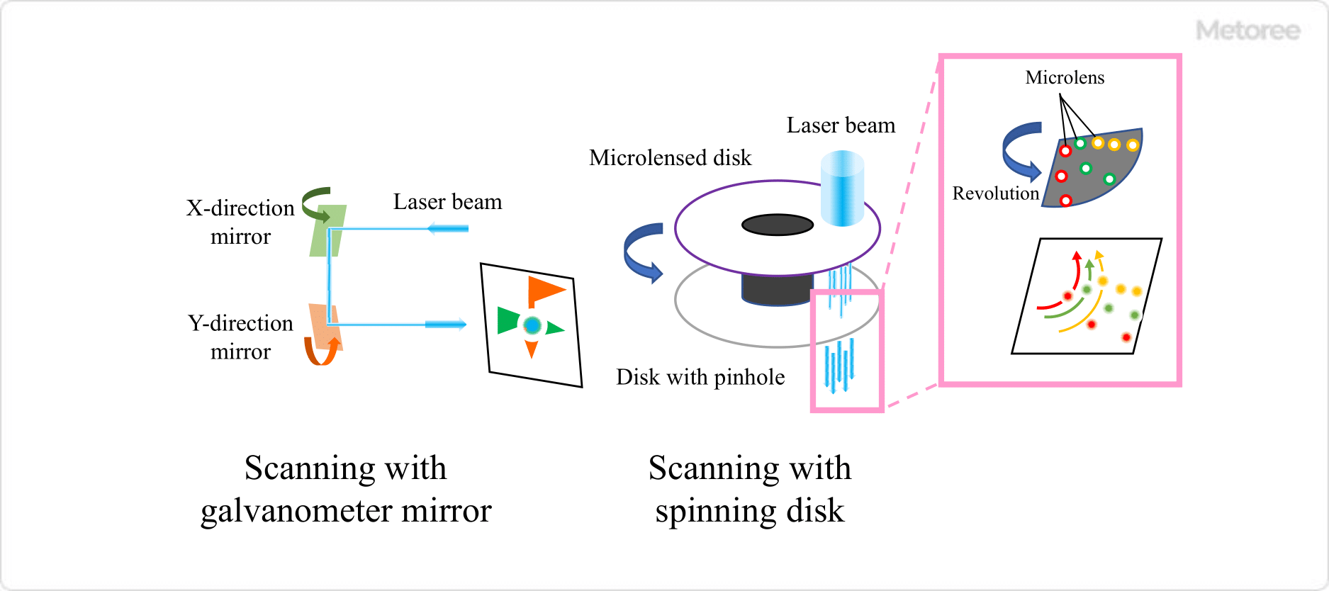
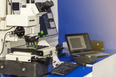
A laser microscope is a type of optical microscope in which a sample can be observed by scanning a laser beam to a light source.

It generally employs confocal optics and is also called a confocal laser scanning microscope or CLSM. A laser microscope has high spatial resolution not only in the horizontal (XY) direction but also in the vertical (Z) direction because the confocal optics can exclude light from out-of-focus surfaces.

Therefore, by measuring microscope images while shifting them in the height direction, it is possible to obtain a three-dimensional image or an all-in-focus image.

Uses of Laser Microscopes

Since laser microscopes use light for measurement, there is no need to touch the sample. For this reason, laser microscopes are used in the industrial field to observe the three-dimensional shapes and surface profiles of precision instruments, such as semiconductors and electronic components. They are also used in the life science field to observe cells and biological tissues labeled with fluorescent substances.

Some manufacturers offer customized measurement stages for laser microscopes, making it possible to measure large samples such as large flat panel displays.

Principle of Laser Microscopes

Laser-Microscopes_レーザー顕微鏡-1.

Figure 1. Comparison of optical and laser microscopes

Laser microscopes are similar to a typical optical microscope configuration of lenses and mirrors, but use a laser as the light source and are designed as a confocal optical system. Laser light is characterized by the uniform wavelength and phase of the emitted light, and by its excellent monochromaticity, directivity, and linearity.

Since ordinary light has different phases and wavelengths, the optical paths are not aligned, and the reflected light generated by irradiating a sample is overlapped by scattered light, making it difficult to obtain a clear image. On the other hand, with laser microscopes, a pinhole is placed at the position where the reflected light is focused through transmission through the lens and reflection from the sample. Therefore, excess light, such as scattered light, can be eliminated. As a result, clean images with clear contours can be obtained.

In addition, there are two methods of obtaining two-dimensional images with laser microscopes: one is to move the stage, and the other is to move the laser mechanism. The features of each method are as follows.

  • The Stage-Moving Method
    A wide area can be measured, but the size of the stage is limited, so large samples cannot be measured.
  • Laser MechanismMoving Method
    A wide range of sample sizes can be measured, and surface microstructures can also be measured.

Scanning Method of Laser Microscopes

Laser-Microscopes_レーザー顕微鏡-2

Figure 2. Laser microscope scanning method

There are various ways to scan with laser microscopes. For example, scanning with a galvano mirror involves mechanically moving the mirror, but a MEMS scanner or resonant scanner method can be used to increase the speed.

The spinning disk method is used for high-speed measurement, in which a laser beam is directed onto a disk lined with many micro-lenses and pinhole arrays to pick up many beams of light simultaneously reflected from the sample. This method can obtain a large amount of information at a time but requires a high-power laser that has sufficient intensity even when spread to some extent.

Other Information About Laser Microscopes

1. Differences Between Laser Microscopes and Electron Microscopes

The electron microscope is another type of microscope with high magnification, but the principles of these instruments are not identical. Laser microscopes use light, while electron microscopes use electron beams, and the magnification, equipment, and measurement techniques are very different.

Because electrons are very short in wavelength compared to visible light, the resolution of electron microscopy is very high; scanning electron microscopes (SEM) can observe structures down to a few nanometers. Laser microscopes, on the other hand, cannot observe structures at wavelengths shorter than their wavelengths and have a resolution of only a few hundred nanometers.

The equipment used for laser microscopy and electron microscopy differs greatly. Electron microscopy uses an electron beam and requires measurement under a vacuum. In addition, when highly insulating materials are measured with electron microscopes, the electron beam may cause charge to accumulate on the surface, distorting the image, and other limitations exist, so care must be taken to determine what the sample’s unique physical properties are.

Also, as a measurement technique, electron microscopy requires skillful techniques for cutting out the surface and optimizing the observation conditions. On the other hand, laser microscopes can be used more universally than electron microscopes because there is no accumulation of electric charge and the surface cutout does not require precision.

2. Surface Roughness Measurement With Laser Microscopes

Confocal laser microscopes can measure the roughness of a sample surface in a non-contact manner. Although atomic force microscopy is the most common method for measuring the roughness of a sample surface, confocal laser microscopy has the advantage of non-contact measurement. Conversely, the resolution differs from that of the atomic force microscope, so the appropriate instrument should be selected depending on the roughness of the sample surface.

カテゴリー
category_usa

Particle Sensor

What Is a Particle Sensor?

A particle sensor is a device that counts the number of particles detected in the air over a certain period.

They are mainly used in clean rooms. Particles here refer to fine particles of foreign matter, and especially in semiconductor manufacturing, these particles must be controlled because they can cause defects and lower yields.

Particle counters are similar in function and application, but particle sensors are capable of continuous measurement, while some particle counters are not.

Particle counters tend to measure more accurately than particle sensors, tend to be larger devices, and many models can be used in liquid as well as air. High-performance models can measure particles 0.1㎛ and larger.

Applications of Particle Sensors

Particle sensors are mainly used in clean rooms to monitor the cleanliness of the room. Specifically, they are used to monitor the cleanliness of automobile painting processes and to control clean rooms in semiconductor manufacturing plants.

The range of applications is expanding. For example, there are particle sensors for in-vehicle use to measure PM2.5, which is believed to have an impact on the human body. Ultra-compact, fairly small models tend to be popular, and some models can be installed on DIN rails or mounted on walls to save space.

Principle of Particle Sensors

Particle sensors operate by two main principles: light scattering and light shielding. Both types of particle sensors have a built-in air suction pump and continuously measure particles at a constant speed, but the method of detecting particles differs.

1. Light Scattering Method

Particle sensors using the light-scattering method detect the scattering of light by a photodiode, which converts the scattered light into an electrical signal. With this method, the size and number of particles can be counted based on the number and strength of the electrical signal caused by the scattering light.

2. Light Shielding Method

Particle sensors using the light-shielding method constantly emit light onto the photodiode. These sensors count the size and number of particles by detecting the electrical signal of the weakening of the particles in the air between the light source and the photodiode as the light passes through.

The accuracy settings of particle sensors require careful attention. Regardless of the method of measurement, if the particle sensor’s measurement accuracy is too high for the cleanliness of the room, the measurement error tends to be large.

To use particle sensors within the desired measurement error for cleanliness control in clean rooms, it is necessary to select a model with an appropriate measurement range.

Other Information on Particle Sensors

1. Difference From Dust Meters

The most significant difference between a dust meter and a particle sensor or particle counter is the concentration of the particulate matter to be measured. Dust meters are usually designed to measure high concentrations of particulates of 0.01 mg/m3 or higher, and their concentration is evaluated based on the weight, not the quantity, of the particulates. On the other hand, particle sensors and particle counters differ in that they quantify their measurements by the number of particulates.

Particle counters, in particular, are mainly for single-shot measurement. They have specifications that are finely divided from Class 1 to Class 9 to withstand measurement in low-concentration, high-cleanliness environments, whereas dust counters are for continuous measurement and have a relatively wide concentration range that can be measured.

2. Portable Particle Sensor

Recently, cleanliness is required in a variety of environments and industries, and the measurement points are not limited to clean rooms.

Manufacturers are developing a variety of particle sensors to improve user convenience. Examples include:

  • Lithium-ion battery-powered sensors that can be connected to a PC via USB for data analysis.
  • Models that can be connected to a multipoint monitoring system.
  • Models that are equipped with a built-in camera.
カテゴリー
category_usa

ID Card Printer

What Is an ID Card Printer?

ID Card Printers
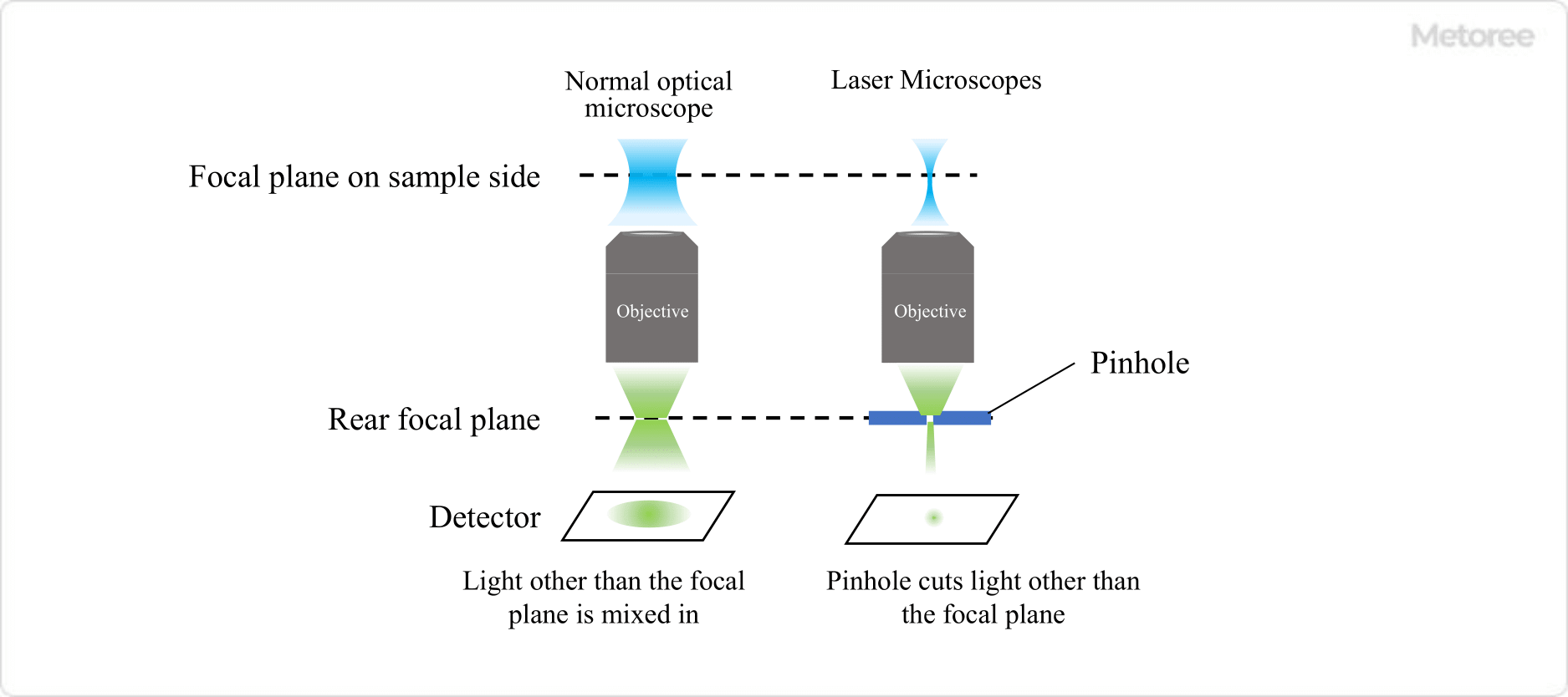
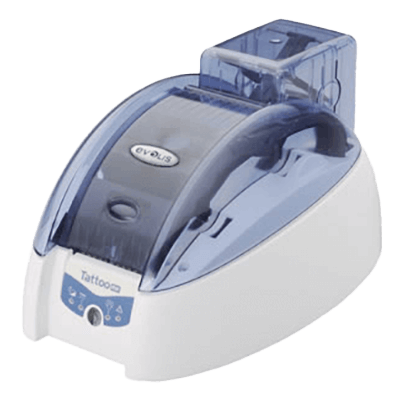
An ID Card Printer is a device that prints employee identification cards and other ID cards.

By installing an ID Card Printer, the risk of leakage of employees’ personal information and the cost of outsourcing can be reduced.

The ink is vaporized by heat and transferred onto a plastic card with an embedded IC chip or magnetic stripe. Printing methods can be classified into direct printing and retransfer printing.

Uses of ID Card Printers

ID Card Printers are used to print employee ID cards and other ID cards for use within a company or facility. They are useful for traffic passes to enhance company security, to manage attendance, and to authenticate electronic devices such as copiers and PCs.

Some products are equipped with an IC encoder that inputs information to an IC chip or a magnetic encoder that inputs information to a magnetic stripe card. When selecting a product, the printing method, the type of card supported for printing, printing speed, and printing finish should be considered.

Principle of ID Card Printer

There are two types of ID Card Printers that print on plastic cards: direct printing and retransfer printing.

1. Direct Printing

Direct printing is a printing method that transfers ink vaporized by heat directly onto the plastic card to be printed. Since fewer processes are required for printing, many inexpensive devices are available, and running costs are low.

However, it cannot print on IC chips and is greatly affected by dust and sebum. Also, depending on the card to be printed, it may not be possible to print on it.

Printing on the edges of cards is not possible. However, cards made of PVC are supported.

2. Retransfer Printing Type

In the retransfer printing method, the image to be printed is printed once on retransfer film, which is then pressed against the card to be printed, and the image is transferred from the film to the card by applying heat.

In addition to providing clear printing, this method can also be used when the surface of the card to be printed is uneven, or even over an IC card. The retransfer method can print on the entire surface of the card, including the edges. On the other hand, running costs are higher due to the use of film and other materials.

Since this method does not print directly, it can print not only on cards made of PVC, but also on cards made of other materials. Examples include polyethylene terephthalate (PET), PET-G, and polycarbonate PC.

Features of ID Card Printer

1. High Quality

Full-edge printing without edges using retransfer technology enables printing of well-designed color images. 

2. High Resolution

With a resolution of 600 to 1,200 dpi, even very small characters can be displayed with high definition. Small QR codes can be laid out while maintaining design quality.

3. High-Function Printer

Encoders can be used to encode contactless IC cards while printing on the card. Inkjet printers can print at speeds of 50 sheets per meter or faster.

4. Integration With Existing Systems

The system can be linked with existing in-house systems, membership management and school management systems, etc.

Other Information on ID Card Printer

1. Advantages of ID Card Printer

There are many advantages to producing employee ID cards, ID cards, student ID cards, membership cards, and medical certificates in-house. First, important personal information of employees, students, members, and patients is not leaked to outside parties.

Second, even a single card can be printed immediately, without being bound by deadlines. This can accommodate personnel changes, etc. Medical examination cards can be issued during the examination and handed in on the way home.

Cost is also an advantage. If cards are printed in-house, the cost is less than 100 yen per card. Another advantage is that cards can be issued in large quantities. It is possible to print 50 or more cards with a photo per minute at high speed.

With inkjet printers, there is no ink ribbon data, further reducing the risk of personal information leakage. High-resolution color printing is possible, enabling beautiful and precise printing of portraits, letters, and design patterns. 

2. Adhesive-Back Card System

Adhesive-backed cards are ID cards that can be used repeatedly. The card is created by printing personal information, etc., and then peeling off the release paper and affixing it to the IC card. By removing the adhesive-backed card, the expensive IC card can be reused.

カテゴリー
category_usa

Universal Board

What Is Universal Board?

Universal Boards

A Universal Board is a board that does not have a fixed wiring pattern, in contrast to a printed circuit board, and is also called a universal board, snake-eye board, or discrete board.

Universal Board can be mounted by inserting components into the holes on the board. Some require soldering, while others are called breadboards, which do not require soldering and can be used repeatedly. Wiring can be easily done by mounting electronic components in the holes on the board and soldering them.

Uses of Universal Board

Universal Boards can be used for a variety of applications, depending on how they are used, since components can be freely installed and wired. Unlike printed circuit boards, which have predefined wiring and locations for electronic components, universal boards are often used for personal electronic construction because of their high degree of freedom in allowing users to install components at their desired locations. They are also included in commercially available electronic construction kits.

In cases where there is no ready-made printed circuit board available, the user must design his or her own circuit board, and in such cases, the universal board can be used to design freely.

Principle of Universal Board

Universal Boards can be divided into two main categories: those that require soldering and those that do not (breadboards). In the former, copper foil is affixed to the holes where components are mounted on the board, and these are called lands. Components are soldered to these lands and connected to the lands of other components with lead wires or other means.

There are two types of lands: one with copper foil on only one side and the other with copper foil on both sides. Some double-sided ones have a through-hole process, which allows for a more flexible design since both sides are conductive.

The latter type of breadboard has a two-layer structure, with a layer with holes for inserting components and a layer with metal rails for inserting wiring. Since wiring depends on the placement of the metal rails, it is less flexible than those that require soldering, but it can be easily mounted by simply inserting and removing components. Besides, since soldering is not required, the board can be reused many times.

Other Information on Universal Board

1. Wiring Method

Wiring a universal board can be done in any way you like, but to avoid mistakes, place the components on the universal board roughly as shown in the circuit diagram (select a universal board suitable for your application). 

2. How to Install the Components

For example, to realize a single power supply circuit using an OP amplifier on a Universal Board, the components should be placed in the following order from the left: input point, input coupling capacitor, input bias circuit, inverting amplifier circuit using an OP amplifier, output coupling capacitor, output level adjustment circuit, and output point.

In addition, one horizontal row at the top of the board is used as the power line and one horizontal row at the bottom as the GND line. This visually obvious arrangement makes it easy to locate the point to be checked when debugging or modifying the circuit. 

3. How to Connect Components

Wires connecting circuits should be made of component leads (component legs), tinned wire, or heat-resistant coated wire. For soldering, preheat the component leads and lands thoroughly so that the solder will fully fuse to them. Be careful not to get solder on adjacent lands, and use flux if the solder does not spread well.

Wire the components together using the component leads and tinned wires. Since component leads and tinned wires are conductive, wiring should be done with careful consideration of component placement and wiring routing to avoid unnecessary contact. When wiring crosses each other, use heat-resistant coated wires to prevent electrical contact. 

4.How to Handle Components

When installing leaded components on a universal board, make sure that there is room for at least one hole so that the lead of the component will not be bent more than necessary. For transistors and other components with model numbers or other information on the package, place them in an orientation that allows you to see the component name. If a wiring mistake is made, use a desoldering machine to suck out the solder, remove the component, and correct the wiring. 

5. Cutting Universal Board

Since the size of Universal Board is determined by each manufacturer, it is not always the size desired by the user. However, they can be easily cut.

  1. Decide on the size and mark the back side (solder side).
  2. Place it on a rubber mat or similar surface with the back side up so that it will not move.
  3. Place a ruler on the mark and cut 1/3 of the board with a cutter.
  4. Cut the cut area with pliers, etc., and fold the board.
  5. Finish the cut surface with a file or sandpaper until there are no burrs or rows of holes on the cut surface.

*The reason for cutting into the backside of the board is to ensure that the land pattern is cut into the board to prevent accidental continuity. Note that cutting the board after soldering is finished is not recommended due to the possibility of circuit damage or injury.

カテゴリー
category_usa

Cylinder

What Is a Cylinder?

Cylinders
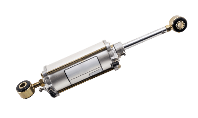
A cylinder is a device that amplifies and converts supplied pressure into propulsive force. Air or oil is used as the pressure source in a cylinder. A cylinder generates thrust through an internal structure based on Pascal’s principle.

The thrust amplified by the cylinder is used for the linear reciprocating or rotary oscillating motion required in the drive units of production equipment. Pneumatic cylinders (air cylinders), which are driven by pneumatic pressure, are used in the automobile, semiconductor, and food industries.

Hydraulic cylinders, which use oil pressure as their drive source, are used in various fields such as construction machinery, heavy machinery, and press equipment.

Uses of Cylinders

Pneumatic cylinders are often used in production plants in the automotive, semiconductor, and food industries. The use of pneumatic cylinders makes it possible to easily and compactly achieve labor-saving and automation purposes, such as moving workpieces. For this reason, pneumatic cylinders are employed in a variety of automated equipment and are utilized in operations such as assembly and transfer.

When the pressure used in pneumatic cylinders is about 0.5 MPa, operations similar to human power, such as linear reciprocating motion and rotational oscillating motion, can be easily realized. Hydraulic cylinders, on the other hand, provide a far higher thrust force than pneumatic cylinders and are used in construction equipment, heavy machinery, and other situations where power is required.

Principle of Cylinders

Cylinders generate thrust using Pascal’s principle. Located on the side of the cylinder are the air and oil supply and exhaust ports, which allow air and oil to enter and exit the cylinders. The pressure supplied through the air supply and exhaust ports moves the piston and rod inside the cylinders back and forth using Pascal’s principle to generate thrust.

When the pressure supplied to the cylinder’s supply and exhaust ports is pneumatic, the thrust is at a small to medium level. When the pressure is hydraulic, the thrust is medium to high. The main components of cylinders are the cylinder tube, piston rod, and front and rear covers.

If we compare it to a syringe, the outer cylinder tube is the cylinder tube, and the piston rod is the part that moves back and forth inside the cylinders. The part that serves as the lid of the cylinders is the front and rear cover. With an air cylinder, a cushion is used in the cover section to absorb the shock when the cylinders are driven.

The packing is used around the circumference of the cylinder’s piston. The packing serves to maintain a tight seal between the cylinder side and the rod side while ensuring accurate movement. Damage to the packing can cause poor sliding properties of the cylinders. Therefore, packing is often treated as a maintenance part.

Types of Cylinders

The internal space of a cylinder is called the cylinder side (or tube side) and the rod side. The rod side is the one where the rod that drives the piston is inside the space. The other side, where there is nothing inside the space, is the cylinder’s side.

1. Double-Acting Cylinders

Double-acting cylinders are designed to extend and retract freely by filling both the cylinder side and the rod side with fluid (generally air or hydraulic pressure) and applying pressure. The piston rod moves back and forth by switching the air supply and exhaust at the air supply and exhaust ports.

2. Single-Acting Cylinders

Single-acting cylinders are driven by pressure fluctuations on one side only. The piston rod moves when pressure is applied to the air supply and exhaust ports, and the rod returns when pressure is exhausted from the air supply and exhaust ports.

How to Select Cylinders

When selecting cylinders, the stroke should be taken into consideration. The stroke of cylinders is the distance over which the cylinder extends and retracts.

The position at which the cylinders are fully extended and fully retracted is called the cylinder’s stroke end. In other words, the stroke end is the position at which the piston cannot move any further.

The maximum stroke distance is determined by the length of the cylinder tube and rod. However, this does not mean that the length can be increased without reproduction. If the diameter is small in relation to the length, machining becomes more difficult. In addition, the longer the length, the more difficult it is to maintain the roundness of the cylinders I.D. and piston O.D. Poor roundness will result in poor airtightness, and the cylinders will not be able to move accurately.

Furthermore, if the diameter is small in relation to the stroke, the cylinders may buckle under high loads during extension. Therefore, the stroke and diameter must be selected to suit the intended purpose.

カテゴリー
category_usa

Clean Booth

What Is a Clean Booth?

A clean booth is a space cleaning system that maintains a positive pressure in a simple space to prevent dust from entering from the outside.

Unlike a clean room, which requires strict control, a clean Booth is used in situations where a localized and simple space cleaning environment is required.

Uses of a Clean Booth

Clean rooms remove dust and other particles from the air at a microscopic level, while at the same time controlling temperature and humidity within a certain range. These performance requirements are standardized by ISO, making it an extremely advanced space cleaning system.

Clean booths, on the other hand, are used when a certain level of cleanliness is required locally, without the need to control the cleanliness of a large area of workspace. For example, they are used in semiconductor manufacturing plants, liquid crystal panel manufacturing plants, pharmaceutical manufacturing facilities, cosmetics manufacturing facilities, and food manufacturing plants.

Clean booths may also be used in conjunction with clean rooms when further improvement of the clean environment is required.

Principle of Clean Booths

_Clean-Booths_クリーンブース-1

Figure1. Principle of a clean booth

In general, clean rooms, the space cleaning environment is strictly controlled using insulation panels to enable control of humidity and temperature, air conditioning, positive pressure equipment to enable room pressure setting, differential pressure damper, and other cleanliness equipment.

In contrast, a general clean booth is a small space composed of a frame, etc., covered with a polyvinyl chloride sheet or the like to shut off the space from the outside, and clean air is supplied by a fan filter unit (FFU) installed on the ceiling of the clean booth to maintain a clean environment. The pressure inside the clean booth is controlled by the FFU. The pressure inside the clean booth is maintained at a positive pressure by the FFU, preventing dust from entering from outside. Depending on the size of the clean booth to be installed, it is most important to select an FFU to maintain positive pressure in the interior space.

How to Use a Clean Booths

The following are points to be considered when using a clean booth.

It is essential to make sure that no dust, dirt, or microorganisms are brought into or generated in the clean booth. It is dangerous to rely solely on the performance of the clean booth. Rules and procedures for using the booth must be determined in advance, and the awareness of the users themselves must also be improved.

Cleaning of FFUs is also important. In particular, failure to clean the inlet port will reduce the cleanliness of the booth, so it is necessary to establish a procedure for periodic cleaning.

The clean booth is a simple system and has a gap at the bottom. Although the inside of the clean booth is controlled at a positive pressure, insects can still enter, and the floor around the clean booth should be kept clean on a regular basis.

The frequency and method of cleaning and the frequency of filter replacement will vary depending on the level of cleanliness required. It is necessary to consider in advance what kind of management is necessary according to the conditions of the environment in which the booth will be used.

Types of Clean Booths

1. Floor Type and Tabletop Type

Clean-Booths_クリーンブース-2

Figure2. Floor and desktop clean booths

The floor type is a large, clean booth installed on the floor and manned by people. They are used for large-scale work. In general, workers entering the booth must wear clean clothes to prevent foreign objects from entering the clean booth. Floor-type clean booth is mainly used in factories and other manufacturing sites.

Table-top clean booths are small clean booths installed on tables. Generally, only hands are allowed inside the clean booth, so workers do not need to wear clean clothes, making it easy to use. Tabletop clean booths are smaller and more compact than other types of clean booths, making them suitable for use in laboratories and factories with limited space. They are also generally easy to install and maintain and relatively inexpensive, so they are used by many companies and research institutes.

2. Closed Type and Open Type

Clean-Booths_クリーンブース-3

Figure3. Open-type clean booth

Closed-type clean booths, which create an enclosed space, are the most common type, but open-type clean booths are also available. An open-type Clean Booth is a type of equipment in which a constant flow of clean air is generated between pairs of airflow units, and work is performed in this space. Compared to closed-type clean booths, open-type clean booths are more portable and are used when a localized workspace needs to be kept in a highly clean environment at the Class 1 level.

3. Standard Type and Custom Type

Clean booth manufacturers sell clean booths of standard sizes and specifications, but they also accept customization from users. The standard type is available in a specified size at a lower cost than the custom type. Custom types can be made in any size desired, and various options can be added, such as adding an FFU anemometer.

Other Information on Clean Booths

1. Curtains for Clean Booths

There are various types of curtains for clean booths with different characteristics, which are selected according to the conditions of the environment in which they will be used.

The functions of curtains include fireproofing, insect repellency, antistatic, heat shielding, and light shielding. Curtains with antistatic functions are effective because static electricity creates an environment where dust and dirt can easily adhere.

2. Clean Booth With Aluminum Frame

Some clean booths are made with aluminum frames.

Advantages of using aluminum frames include the following:

  • Lightweight
    Aluminum is a very light metal, with a specific gravity of approximately 2.7 for aluminum and 7.8 for steel. Aluminum weighs about 1/3 of iron.
  • Manufacturing Costs and Time Can be Reduced.
    Aluminum frames are often anodized on the surface. This reduces the number of processes, such as plating and painting, leading to cost and time savings.
  • Easy to Make Design Changes
    Since aluminum is a soft metal, it is easier to process than other metals. It is also relatively easy to drill or cut holes later.
カテゴリー
category_usa

Water Detection Sensor

What Is a Water Detection Sensor?

Water detection sensors are sensors that detect water using long-wavelength light absorbed by water molecules.

General photoelectric sensors can detect most liquids, but since water is transparent, it becomes difficult to detect because of low light attenuation and penetration. Additionally, colored water or water with different color densities is even more difficult to detect because the amount of attenuation changes.

Water detection sensors, on the other hand, use long-wavelength light that is absorbed by water molecules, making it possible to detect transparent water, colored water, and water with different color densities.

Applications of Water Detection Sensors

Water detection sensors are used to detect the presence of water itself because they use long-wavelength light that is absorbed by water molecules. Examples include monitoring water at production sites where water is used, detecting the liquid level of water storage tanks, detecting liquid levels, and detecting whether plastic bottles or transparent glass containers are filled with liquid.

Also, since these sensors can stably detect even atomized water, they are used to monitor spray-based washing processes in business establishments.

Principle of Water Detection Sensor

Water detection sensors, like photoelectric sensors, detect the presence or absence of water by emitting light through a light emitter and receiving it at a sensor. 1.45um (1450nm) long wavelength light is used to enhance the absorption of water molecules.

By using long-wavelength light that is absorbed by water molecules, water detection sensors can stably detect water even in clear water, colored water, and water with different color densities, as the light is absorbed and intercepted by water molecules.

Other Information on Water Detection Sensor

1. Water Detection Sensors With Photo Refraction or Capacitance Detection

Water detection sensors are, in principle, divided into a light emitter and a light receiver, so they must be installed on both sides of the area where detection is to occur. While this is not a problem in an environment where installation space is available, it is not suitable for detecting water in pipes or pipelines in a confined space.

In such cases, compact, light-refractive water detection sensors or capacitive water detection sensors are suitable. Light refraction sensors detect water based on the difference in whether LED light passes through or reflects off the pipe, depending on the presence or absence of water. Capacitance detection sensors, on the other hand, detect the presence or absence of liquid by reading the change in the dielectric constant.

Both only require a single part, can be compactly installed on one side of a pipe or conduit, and can be used in environments where it is difficult to install long-wavelength light types. 

2. The Difference Between Water Detection Sensors and Humidity Sensors

Water detection sensors detect the presence of water utilizing long-wavelength light, while humidity sensors use a humidity-sensitive membrane to electrically detect changes in resistance and electrostatic capacitance caused by water droplets between comb-shaped electrodes, and correct for humidity.

The main purpose of water detection sensors is to detect the presence or absence of water. But the main difference is that the humidity sensor can, in principle, detect minute water droplets, so the percentage of water droplets in the atmosphere can be calculated and converted to humidity. 

3. Water Detection Sensors in Smartphones

Recently, some smartphone models warn the user when a drop of water is detected on the USB power cord because of the risk of corrosion or deterioration of the electrode during charging. This principle also detects the resistance or capacitance change between the electrodes by converting it into an electrical voltage change.

However, there are still not many models that have such sensors that detect moisture. Many of the temperature and humidity displays often seen on smartphones are based on the identification of the current location using the GPS function, and the temperature and humidity information at that location is obtained and displayed.