What Is Universal Board?
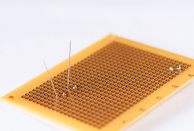
A Universal Board is a board that does not have a fixed wiring pattern, in contrast to a printed circuit board, and is also called a universal board, snake-eye board, or discrete board.
Universal Board can be mounted by inserting components into the holes on the board. Some require soldering, while others are called breadboards, which do not require soldering and can be used repeatedly. Wiring can be easily done by mounting electronic components in the holes on the board and soldering them.
Uses of Universal Board
Universal Boards can be used for a variety of applications, depending on how they are used, since components can be freely installed and wired. Unlike printed circuit boards, which have predefined wiring and locations for electronic components, universal boards are often used for personal electronic construction because of their high degree of freedom in allowing users to install components at their desired locations. They are also included in commercially available electronic construction kits.
In cases where there is no ready-made printed circuit board available, the user must design his or her own circuit board, and in such cases, the universal board can be used to design freely.
Principle of Universal Board
Universal Boards can be divided into two main categories: those that require soldering and those that do not (breadboards). In the former, copper foil is affixed to the holes where components are mounted on the board, and these are called lands. Components are soldered to these lands and connected to the lands of other components with lead wires or other means.
There are two types of lands: one with copper foil on only one side and the other with copper foil on both sides. Some double-sided ones have a through-hole process, which allows for a more flexible design since both sides are conductive.
The latter type of breadboard has a two-layer structure, with a layer with holes for inserting components and a layer with metal rails for inserting wiring. Since wiring depends on the placement of the metal rails, it is less flexible than those that require soldering, but it can be easily mounted by simply inserting and removing components. Besides, since soldering is not required, the board can be reused many times.
Other Information on Universal Board
1. Wiring Method
Wiring a universal board can be done in any way you like, but to avoid mistakes, place the components on the universal board roughly as shown in the circuit diagram (select a universal board suitable for your application).
2. How to Install the Components
For example, to realize a single power supply circuit using an OP amplifier on a Universal Board, the components should be placed in the following order from the left: input point, input coupling capacitor, input bias circuit, inverting amplifier circuit using an OP amplifier, output coupling capacitor, output level adjustment circuit, and output point.
In addition, one horizontal row at the top of the board is used as the power line and one horizontal row at the bottom as the GND line. This visually obvious arrangement makes it easy to locate the point to be checked when debugging or modifying the circuit.
3. How to Connect Components
Wires connecting circuits should be made of component leads (component legs), tinned wire, or heat-resistant coated wire. For soldering, preheat the component leads and lands thoroughly so that the solder will fully fuse to them. Be careful not to get solder on adjacent lands, and use flux if the solder does not spread well.
Wire the components together using the component leads and tinned wires. Since component leads and tinned wires are conductive, wiring should be done with careful consideration of component placement and wiring routing to avoid unnecessary contact. When wiring crosses each other, use heat-resistant coated wires to prevent electrical contact.
4.How to Handle Components
When installing leaded components on a universal board, make sure that there is room for at least one hole so that the lead of the component will not be bent more than necessary. For transistors and other components with model numbers or other information on the package, place them in an orientation that allows you to see the component name. If a wiring mistake is made, use a desoldering machine to suck out the solder, remove the component, and correct the wiring.
5. Cutting Universal Board
Since the size of Universal Board is determined by each manufacturer, it is not always the size desired by the user. However, they can be easily cut.
- Decide on the size and mark the back side (solder side).
- Place it on a rubber mat or similar surface with the back side up so that it will not move.
- Place a ruler on the mark and cut 1/3 of the board with a cutter.
- Cut the cut area with pliers, etc., and fold the board.
- Finish the cut surface with a file or sandpaper until there are no burrs or rows of holes on the cut surface.
*The reason for cutting into the backside of the board is to ensure that the land pattern is cut into the board to prevent accidental continuity. Note that cutting the board after soldering is finished is not recommended due to the possibility of circuit damage or injury.