カテゴリー
category_usa

Electronic Form

What Are Electronic Forms?

Electronic forms are scanned and digitized forms created in Word or Excel on a PC or paper forms, and are a legally valid method of document storage.

Eliminating paper forms not only reduces the space required for storage but also reduces the use of paper as an environmental resource and can cut costs down to printing costs and stamp fees. For businesses, electronic forms can also improve operational efficiency.

By shifting from paper to electronic forms, the risk of data loss due to natural disasters and other causes is also increased.

Uses of Electronic Forms

Electronic forms are used to replace paper-based ledgers electronically, that record transactions in a company and vouchers that objectively certify those transactions.

Many companies use electronic ledgers mainly for accounting work, and the following are examples of their use

1. Report Creation and Management

Field work reports and sales reports are input and sent from smartphones, tablets, and other terminals to improve efficiency and share information.

2. Management of Order Forms

It is not unusual for a retailer to receive several hundred orders a day via fax; by connecting faxes to an electronic form system and storing them electronically, storage space can be reduced and retrieval made easier.

3. Approval and Management of Approval Documents

In addition to digitizing the creation of approval requests, the approval cycle is also placed in the workflow to allow the progress to be monitored. In addition, information can be easily shared within the company.

Principle of Electronic Forms

Electronic forms are digitalized versions of books of account and vouchers that were previously created on paper. For example, they are created and saved in Excel, Word, and PDF formats.

Electronic forms also include scanned paper documents converted to PDF or other image data. Time stamps are used to protect against tampering and to prove when the data existed.

Electronic Forms that are time-stamped at a specific time can prove that they have not been modified since then.

How to Select an Electronic Form System

When choosing an electronic form system, the following points should be considered:

1. Clarification of the Scope of Work

Electronic Forms systems have functions such as creation, distribution, storage, and management, but they do not have all of these functions. It is important to select a system that has the necessary functions according to the scope of your business and your needs. 

2. Consideration of the Burden on Users

When implementing an electronic form system, it is desirable to reduce the burden on users (both internal and external) as much as possible. For example, an interface with good operability and visibility, and an output method that is compatible with a variety of terminals and formats, are examples of such features.

3. Security Governance Perspective

Since electronic form systems often handle personal and confidential information, security measures are essential. In addition to basic functions such as data encryption and access restrictions, it is necessary to select a system that takes legal compliance and internal control into consideration.

4. Level of Support

Electronic form systems may require maintenance and troubleshooting even after installation. Therefore, it is important to check the support system and service level.

Other Information on Electronic Forms

1. Main Functions of Electronic Forms System

Form Creation Function
This function is used to design the layout and items of ledger sheets. You can freely create forms using design tools and templates.

Report Distribution Function
This function is used to distribute form data to other parties. Forms can be attached to an e-mail as a file or downloaded with a URL.

Forms Management Function
This function centrally manages form data. You can search by keywords and conditions, and check the browsing history and change history.

Security Function
Security functions are to prevent falsification or leakage of form data. Mechanisms such as user authentication, locks, and time stamps are available. 

2. What is the Electronic Bookkeeping Act?

The Electronic Bookkeeping Act is a law enacted in July 1998 regarding the electronic storage of Electronic Forms. Previously, national tax-related documents had to be stored in paper form.

However, the Electronic Bookkeeping Act allows documents to be stored in electronic form. Furthermore, the 2015 amendment eliminates the need for electronic signatures for electronic books, and contracts and receipts of 30,000 yen or more are now covered by the law.

Although prior application to the tax office was required in order to use the Electronic Bookkeeping Act, prior application is no longer required as of January 1, 2022. In addition, the output and storage on paper of data exchanged through electronic transactions is no longer permitted.

There are many other documents that are subject to the Electronic Bookkeeping Act, but please note that documents that are not subject to the Act cannot be stored electronically.

  • Accounting documents such as journal ledgers, accounts receivable ledgers, purchase ledgers, accounts payable ledgers, and fixed asset ledgers
  • Financial documents such as inventory sheets, balance sheets, profit and loss statements, etc.
  • Documents such as contracts, receipts, bank books, quotations, invoices, etc.
カテゴリー
category_usa

Pass Box

What Is a Pass Box?

A pass box is a device installed between two rooms of different cleanliness classes, such as a clean room.

It is used to transfer goods and equipment between the outside and the clean room and is used to prevent the introduction of particulates, bacteria, fungi, and other substances into the clean room that could cause product or operation failure or contamination.

Pass boxes make it easier and less contaminated to bring items in and out of two rooms of different cleanliness classes. They do so without the need for a human being to move in and out of the two rooms. It is also cost-effective because labor costs are not cut by changing clothes, etc. Since pass boxes are part of the facility, they are installed during the construction or expansion of a factory.

Uses of Pass Boxes

Pass boxes are used in manufacturing plants and research institutes that have rooms of different cleanliness classes.

They are used in a wide range of fields, including the manufacture of semiconductors, LCDs, electronic components, printing, precision instruments, and other products where the quality of the product depends on the presence of particulate matter, as well as in pharmaceutical plants, sterile treatment rooms, culture and other places where microbial contamination is a concern.

There are various types of pass boxes on the market, including standard, shower, and conveyor types, and selecting the appropriate type for the intended use and operating environment will lead to more efficient operations.

Principle of Pass Boxes

There are several types of pass boxes, including the standard type with only two doors, the shower type with an air shower inside, and the automatic type with a conveyor.

Pass boxes also have an airlock function to protect the clean room from contamination.

Other Information on Pass Boxes

1. Types of Pass Boxes

Standard Type
Standard pass boxes have a simple structure with two doors on each side. Many of them have an interlock function to prevent the opening of the other door when one side is open. By releasing the doors on both sides, contamination is prevented from being brought in directly from a room with a low cleanliness level.

Shower-type Pass Box
In a shower-type pass box, an air shower blows jets of air from the surrounding area when objects are placed inside the pass boxes. This is done to blow away surface particulates and bacteria and prevent them from moving while still attached.

The air is supplied and purified by a HEPA filter. However, since air showers can only blow air onto surfaces, they are not effective in areas where objects overlap each other and are not a panacea.

Automatic Pass Boxes
Forklifts are commonly used to transport goods in factories. When manufacturing precision equipment or pharmaceuticals in a clean room, conveyor-type pass boxes are installed to carry on whole pallets. Conveyor-type pass boxes are also equipped with an air shower to prevent the introduction of particulate matter from the outside.

Circulation-type Pass Boxes
Other types of pass boxes are also available that circulate normal air through the pass boxes to prevent contamination of the interior and to clean the goods and materials to be delivered.

2. How to use Pass Boxes

When manufacturing quality products, people and objects can cause dust and bacterial contamination. The use of pass boxes eliminates the effects of particulate matter from clothing and prevents the attachment of particulate matter and bacteria. It also reduces the movement of people across the cleanliness area and allows only objects to be brought in. In this way, a clean environment is maintained in the clean room.

Specific instructions for use are as follows:

Open the door on the opposite side of the clean room and wipe the inside of the pass boxes using ethanol or other liquids. The cleaning method varies depending on the application, but if the items to be moved can also be cleaned and placed in the pass boxes, they are placed in the pass boxes.

If the pass boxes are equipped with a UV irradiation function, the UV lamp will automatically turn on for a set period after the door is closed to perform UV sterilization. If the pass boxes are equipped with an air shower, after closing the door, jet air is blown to remove dust from the outer surface.

After a certain period has elapsed after the jet air has finished blowing, the other door is opened and the items are taken into the clean room after the blown dust has settled.

3. A Glove Box with Pass Boxes

Glove boxes are used when handling substances or germs that are dangerous to handle directly, such as when handling air-sensitive materials or when working under chemically inert conditions.

Some glove boxes are circulated by an external pump, while others can be connected to a vacuum pump. Some glove boxes are equipped with pass boxes. The pass boxes minimize the amount of outside air carried into the glove box.

カテゴリー
category_usa

FPC

What Is an FPC?

FPCs
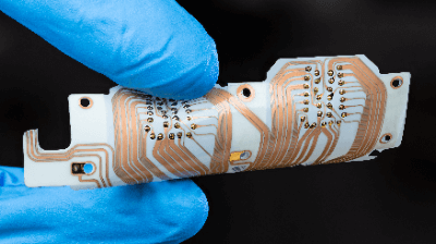
An FPC is a flexible printed circuit board. It is characterized by its paper-thinness and softness. Since it is lighter, smaller, and more economical than ordinary substrates, it has come to be widely used in recent years.

An FPC is also called flexible substrate, an acronym for Flexible Printed Circuits.

Uses of FPCs

FPCs are widely used in electrical appliances and consumer products. A typical application is smartphones. In most cases, FPCs are used in the control boards of smartphones. Because of their small size and lightweight, FPCs are useful for products that are carried daily.

In-home appliances, FPCs are used in LCD TVs. Since electronic control boards can be made smaller, they are economically advantageous. Other products include keyboards and printers, which have a wide range of uses. In addition, they are also used in heavy industry. In recent years, it has become a must-have component in the space development and aviation industries.

Principle of FPCs

The mechanism of an FPC is the same as that of a printed circuit board, but the biggest difference is that the base material is a film. Circuits are printed on insulating polyimide or polyester film with copper or other metals as wiring. Both the film and copper foil are about 12 µm to 50 µm, so they can remain quite thin even when laminated together.

FPCs are fabricated in the following manner.

  1. A thin copper foil is attached to a base film with an adhesive, such as epoxy resin.
  2. Dry film is coated on this base material for etching.
  3. UV light is irradiated to transfer the circuit diagram onto the dry film.
  4. The required portion of the circuit diagram remains on the dry film, and etching completes the circuit pattern on the copper foil.
  5. The dry film is peeled off, and an insulator film is applied to the entire surface for plating.

The above process completes lightweight and durable FPCs. there are two types of FPCs: single-sided FPCs and double-sided FPCs. While double-sided FPCs are less durable than single-sided FPCs, the advantage of double-sided FPCs is that they can be designed with higher density. In double-sided FPCs, the process of single-sided FPCs is repeated.

In recent years, FPC substrates with a flex-rigid structure and multilayered FPC substrates, in which a rigid substrate is sandwiched between FPCs, have also been developed. As a base material, polyimide is more heat-resistant and durable than polyester.

Other Information on FPCs

1. Characteristics of FPC

FPCs have three characteristics: high flexibility, lightweight, and high cost.

  • High flexibility
    Plastic films such as polyimide are used as the material for FPCs. Plastic films are used for moving parts of electronic devices because of their flexibility and bendability.
  • Light in Weight
    FPCs are made of plastic and are lightweight. This is a necessity in the space and aviation industries, where weight restrictions are strict.
  • Expensive
    FPCs tend to be more expensive than rigid boards, which are regular printed circuit boards.

2. Points to note when using FPCs

There are two major points to note when using FPCs.

  • Difference in Bending Resistance
    FPCs are characterized by high flexibility, but their flex resistance differs among manufacturers and products.
  • Mechanical Weakness
    FPCs are light and thin films, making them mechanically weak. When mounting components, a plate called a reinforcing plate must be attached to the electronic components.

FPCs must be used in consideration of the above points.

3. Increase in the Size of the FPC Market

According to a study by Credence Research, the global FPC market is increasing year by year; it is projected to grow at a CAGR of 10.6% from 2018 to 2027, and the global market size for flexible electronics is expected to grow to approximately 4.5 trillion yen by 2027.

The growing market is related to the rising demand for FPCs in the automotive, consumer electronics, and aerospace industries.

カテゴリー
category_usa

Twin Timer

What Is a Twin Timer?

A twin timer is a type of timer relay function that allows the ON time and OFF time to be set separately.

Flicker operation can be set for timer relays. Flicker operation is an operation in which the ON time and OFF time continue to repeat alternately when a voltage or start signal is applied to the relay.

In a normal flicker operation, only one ON time and one OFF time can be set in common. However, in a timer relay with twin timer function, each of these can be set individually.

Uses of Twin Timers

Twin timers are used in electronic devices and machinery that require separate ON and OFF time settings. Typical examples are lamps and signal towers. Twin timers are also used in other machines that need to be run and stopped at regular intervals.

For example, a twin timer can be used to turn a lamp on for 5 seconds and then off for 3 seconds, or to rotate a gear for 3 seconds and then stop for 5 seconds, or when a device needs to be turned on and off separately.

Principle of Twin Timers

A timer relay consists of four parts: an input part, a timekeeping part, a power supply part, and an output part. The input section receives signals from the device and passes them to the timekeeping section. The timekeeping section measures time and passes the signal to the output section after a set time has elapsed.

The output section then outputs the signal to various devices. The power supply section supplies voltage to the timer relay. When the power supply part of the timer relay is turned on, or when the signal for start is sent to the input part while the power supply voltage is applied, the timer relay starts operating.

Types of Twin Timers

In addition to flicker operation, timer relays have other modes of operation such as on-delay operation, off-delay operation, and interval operation. The twin timer is one of these timer relays that performs flicker operation.

When the timer relay is set to off-start, it repeats the off/on/off sequence, and for on-start, it repeats the on/off/on sequence in reverse. With the twin timer, the on-time and off-time can be set alternately, and this allows the timekeeping unit to either send a signal to the output section or stop the signal.

Other Information on Twin Timers

Types of Twin Timers in Digital Timers

A digital timer is a timer that can be switched on and off after a pre-set numerical period of time has elapsed. The following four types of twin timers in digital timers are available:

They are classified according to whether or not they have a power reset operation and a power holding operation for flicker off start and flicker on start, respectively.

1. Toff Mode
This mode starts timing at the rising edge of the signal input while power is being applied and repeats OFF and ON. A reset occurs when the power supply is turned OFF, and can also be reset by inputting a reset signal other than the power supply or by using the reset key on the main unit.

2. Ton Mode
This mode also starts timing at the rising edge of the signal input, repeating ON and OFF as in the toff mode described above, but differs in that it always starts from ON.

Like toff mode, this mode is reset when the power is turned off.

3. Toff-1 Mode
Like toff mode, this mode starts timing at the rising edge of the signal input while power is being applied, and repeats OFF and ON.

It differs from toff mode in that it retains the previous time even when the power is turned off. After power is applied again, timekeeping starts from the beginning when the signal input turns ON. Reset can be done by inputting a reset signal or by pressing the reset key.

4. Ton-1 Mode
In the toff-1 mode, the timekeeping starts from ON after the rising edge of the signal input and repeats ON and OFF.

カテゴリー
category_usa

Terminal Relay

What Is a Terminal Relay?

Terminal Relays
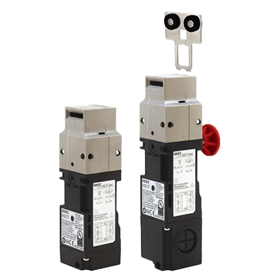
A terminal relay is an input/output signal processing device that integrates multiple relays and terminal blocks.

It is used as an interface device to relay I/O of programmable controllers and solenoid valves. The main structure of a terminal relay, which plays the role of I/O interface device, is a terminal block on a pedestal with a built-in printed circuit board, and multiple independent single-pole type small relays can be mounted on this pedestal according to the application, as a compact relay structure while excelling in maintainability, This contributes to downsizing of equipment and reduced wiring.

Uses of Terminal Relays

Terminal relays are mainly used in industrial applications.

The following are examples of terminal relay applications:

  • For internal signal communication in presses and processing machines
  • For relaying signals between large pumps and fans and control equipment
  • For relaying signals from slurry processing equipment

Generally, microcomputers, PLCs, and other control devices are used to control large industrial equipment in complex ways. While these control devices are capable of complex internal processing, the allowable output signal current is often small. Conducting large currents through these devices may have adverse effects, such as accelerating failure frequency.

Therefore, if you wish to control equipment with large load currents or inrush currents, such as solenoid valves, isolate the outputs of the control equipment by means of relays. However, installing multiple power relays and other relays side by side occupies space and complicates control wiring.

Terminal Relays are a device that combines a terminal block and relay into a single unit, allowing a lineup of small, single-pole relays. Therefore, space and wiring savings can be achieved.

Principle of Terminal Relays

Terminal relays are composed of terminal block components and relay components.

1. Terminal Block Component

The terminal block component consists of a relay socket and a terminal block. The part that conducts electricity is made of copper or iron screws, and the casing is made of hard synthetic resin. Many products are fixed by tightening the external wiring, which is processed with round terminals, etc., with iron screws.

Generally, most products have sockets that can accommodate four relays, with two inputs and two output terminals per relay. 16-point products are also available. Terminal Relay is sometimes referred to as a relay terminal.

2. Relay

A relay is a component that insulates and relays signals. Terminal relays are generally small, single-pole relays. It is often installed by inserting it into a terminal block component with a pin on the back side. Relay specifications are often printed on the casing on the relay surface, and products with various power supply specifications and signal types are sold.

How to Select a Terminal Relay

When selecting a terminal relay, the following considerations should be taken into account:

1. Number of Output Points

The number of output points is the number of points that can be output by the terminal relay. Most general-purpose products have 4 output points, but there are products with 16 or 32 output points for connection to PLCs. In the case of a system that controls many devices, the more output points, the less wiring is required.

2. Input Specifications

The input specification is the type of signal input to the coil portion of the relay. 100 VAC, 24 VDC, and other specifications are available. Select the input specification according to the output specification of the control equipment.

3. Output Specification

Output specifications are the specifications of the signals output by the relay. Factors such as signal type and rated energizing current are included.

Signal types are mainly classified into contact and non-contact. With contacts, the signal is transmitted by mechanically operating a metal section with an electromagnetic coil. It tends to have a large allowable current and has the advantage of being heat resistant. However, it has the disadvantage that the contact parts gradually wear out due to opening and closing operations.

The non-contact method uses semiconductors or solid-state relays to transmit electrical signals. Since there is no physical drive, it can withstand high open/close frequencies and high speed open/close operations. However, they are susceptible to heat and have drawbacks, such as semiconductor components that can fail if currents exceeding their rated currents flow through them.

The rated current rating is the amount of current that can be conducted. The larger the current value, the more capable it is of controlling large loads, but the larger the relay often becomes. Generally, when used as terminal relays, most products have a current-carrying capacity of 1 to 5 A.

カテゴリー
category_usa

Tactile Switch

What Is a Tactile Switch?

Tactile Switches
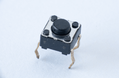
A tactile switch is a momentary-type switch that is energized by a click when a person presses it.

Tactile” here means “palpable” or “tactile” and is also called a tact switch. Tactile switches are generally installed on printed circuit boards.

They are characterized by the fact that when a switch is pressed; it provides feedback of the sensation of having been pressed. For this reason, they are widely used in all electronic devices that are operated by humans. Installation methods are broadly classified by whether they are inserted into a hole in the PCB or mounted on the surface of the PCB, and further classified by whether they have a seal that is effective in preventing dust, etc.

Uses of Tactile Switches

Tactile switches are used in a wide range of equipment that requires human operation, including communications equipment, office automation equipment, laboratory equipment, medical equipment, and remote control units for home appliances. At the design stage of the board on which tactile switches are used, it is necessary to identify and select whether they are to be embedded in holes or mounted on the surface properly.

If tactile switches are to be used in precision equipment or in machines that have a large loss in case of failure, it is better to select tile switches with a sealed structure that is highly reliable and has waterproofing and dustproofing effects. By using different stroke lengths at the time of pushing depending on the product, it is possible to make a product that can be touched quickly and continuously, or to make a product that cannot be activated unless it is pushed with strong force.

Principle of Tactile Switches

Tactile switches have a mechanism whereby when a plate called a push plate inside is manually pushed, an electric current flows through the switch when the electrical switch contacts formed inside the switch make contact with each other, causing the switch to operate. A tactile switch consists of an enclosure, a push plate, a film, a metal dome, three contacts, and a mounting base.

The metal dome is a conductor with a dome shape. Two contacts are attached to the edge of the dome and another contact is attached to the mounting base in the center of the dome. When the push plate of a tactile switch is pressed by hand, the center of the metal dome is crushed and the contacts in the center of the dome make contact with the metal dome. The contact point and the metal dome make contact, allowing the current to pass through the three contacts and turning the switch ON.

Conversely, when your hand leaves the push plate of the tactile switch, the metal dome and the contact point in the center of the metal dome separate, turning the switch OFF.

Other Information About Tactile Switches

1. Repair of Tactile Switches

Tactile switches are generally durable enough, but they can fail depending on where they are used and how often they are used. Repair will be performed, but in some cases, such as with older products or the manufacturer no longer exists, it may not be possible to request repair. Nevertheless, if soldering can be performed, replacement with a new one by the user can be handled.

Check the part number from the failed tactile switch and investigate whether an identical tactile switch can be obtained. If not, it is not too difficult to find a similar tactile switch based on the external dimensions. This is because tactile switches are standardized to some extent.

2. Axis Color of Mechanical Keyboards

There are several types of mechanical keyboards for PCs, such as red-axis, brown-axis, and blue-axis. These are derived from the fact that key switches made by a German manufacturer, a major manufacturer of key switches for keyboards, have different axis colors for each type. Since the axis color changes for each type of key switch, it is possible to identify the type of key switch by checking the axis color.

Among these key switches, the key switch with a brown shaft is called a tactile type. However, tactile switches are not actually used, but are simply referred to as such by the manufacturer due to the structure of the key switch (i.e., the feel of the keys).

There are six main keyboard shaft colors: red, pink, silver, black, brown, and blue. Each keyboard has a different feel, but this difference in feel comes from the key switch structure, which itself is identical.

3. Tactile Switches and Haptics

In addition to tactile switches, haptics, a haptic technology that creates the feeling of an object as if there is an operation button that does not actually exist, by applying vibration when operating a smartphone, is being actively developed these days, especially by electronics manufacturers.

With the application of advanced interactive communication technologies such as VR and AR, technological progress is very rapid to incorporate haptic technologies that make it seem as if we are touching objects in a virtual space. In the near future, tactile technology evolved from tactile switches is expected to play an active role in areas such as telemedicine and robot operation.

カテゴリー
category_usa

Safety Door Switch

What Is a Safety Door Switch?

Safety Door Switches

Safety door switches are safety devices used to check the open/close status of safety fence doors and covers.

Many industrial machines are subject to powerful torque and pressure, and if a machine is activated while a door or cover is open, personal injury may occur. Therefore, they are often used as interlocking mechanisms to prevent equipment from starting when it is possible to enter a safety fence, or to stop equipment when a tobira is opened.

Various safety standards exist, such as ISO 14119, and standard products do not lose their function as safety sensors even in the event of a single failure. Selecting a safety door switch with a certification mark issued by a national or international certification organization will ensure a higher level of safety.

Uses of Safety Door Switches

Safety door switches are used for safety or device protection. The following are examples of applications for safety door switches:

1. Machine and Robot Control

Safety door switches are used to control the starting and stopping of machines and to ensure the safety of industrial robots. Most of the industrial machines used in manufacturing have safety barriers outside their range of motion, and in most cases, these are safety door switches. They are designed to automatically stop the machine when a door or cover is opened, preventing personal injury.

2. Security Applications

Safety switches may also be used for building security. Safety door switches are installed on the entrance and exit doors of buildings to prevent unauthorized entry by triggering an alarm when the door is unintentionally opened or closed.

3. Medical Equipment

Safety door switches are also used in medical equipment to protect machines and improve safety. e.g., MRI (magnetic resonance imaging) laboratories have doors with safety door switches that interrupt the examination when opened or closed. Safety door switches play an essential role in ensuring the safety of MRI examinations.

Principle of Safety Door Switches

A safety door switch consists of a sensor and a control circuit.

1. Sensor

Sensors are the components used to detect whether a door or cover is open or closed. They are shaped like microswitches, limit switches, or magnetic reed switches. They detect the open/close state of the door and feed back signals to the control circuit.

2. Control Circuit

The control circuit is an electrical circuit responsible for automatic stopping of the machine, etc. The control circuit is activated by feedback from the sensor and automatically stops the machine when the door is opened.

It is sometimes used in combination with an emergency stop switch. The emergency stop switch quickly stops the machine in the event of a hazard.

The combination of safety door switches and emergency stop switches provides greater protection for the operator and those around him.

Types of Safety Door Switches

Safety door switches can be classified into two main types: non-contact and electromagnetic lock.

1. Non-contact Type

Non-contact door switches are door switches with an internal reed switch. A dedicated actuator is attached to the switch, which detects the opening and closing of the door using a built-in magnet. Since it does not make contact with the door, it features few parts that are subject to mechanical wear.

While general reed switches can open and close contacts by using a magnet, safety door switches are designed to require the use of a dedicated actuator. This is to prevent malfunction of the reed switch.

2. Electromagnetic Lock Type

The electromagnetic lock type is a door switch with an electromagnetic lock function to lock the door. By selecting an electromagnetic lock type, it is possible to prevent accidental entry by locking the door. Generally, an interlock is provided to stop the equipment if the door is forcibly pried open when the door is locked.

Other Information on Safety Door Switches

Similar Safety Devices

Safety devices similar to safety door switches include light curtains and laser scanners. These devices detect intrusion by blocking visible and infrared light.

In recent years, light curtains and laser scanners have been increasingly used in manufacturing to save space and flexibly accommodate layout changes.

カテゴリー
category_usa

DC Axial Fan

What Is a DC Axial Fan?

A DC axial fan is an axial fan that uses a DC power source to cool equipment.

The purpose of installing a DC Axial fan is to exhaust the heat generated inside the equipment to the outside or, conversely, to supply heat from the outside to the inside of the equipment. This makes it possible to control the temperature inside the equipment.

Generally, heat is generated when equipment is operated. If left unchecked, the temperature of the electronic components inside the equipment will rise, resulting in failure or damage in the worst case. In this case, a DC axial fan can be used to exhaust the heat generated in the equipment and prevent accidents from occurring.

Uses of DC Axial Fans

The main use of DC axial fans is to cool electronic components such as capacitors and ICs in notebook and desktop PCs, control panels, measuring equipment, OA equipment, communication equipment, power supplies, and medical and scientific equipment.

DC axial fans are also used to ensure long-term stable use and temperature control of automobile cooling fans, air conditioner fans, etc.

Principle of DC Axial Fans

A typical DC axial fan consists of a bladed plastic or metal cooling fan attached to a motor driven by a DC power source. Air is drawn in from the front of the fan and exhausted out the back to cool the inside of the equipment. Conversely, some fans intake air from the rear of the fan and exhaust air from the front.

Axial fans are fans that blow air in the axial direction. They are the most efficient of all turbo fans and are widely used for cooling heat-generating devices. Axial fans are characterized by the fact that the increase or decrease in airflow due to resistive objects is relatively small. When axial fans are installed in equipment, noise and power consumption of the equipment can be reduced by setting the operating point of the fan to the maximum airflow side.

Furthermore, in recent years, DC axial fans with PWM (Pulse Width Modulation) control, used in notebook and desktop PCs, have the ability to externally control the fan’s rotation speed. This allows for appropriate control of environmental temperatures.

How to Select a DC Axial Fan

When selecting a DC axial fan, first estimate the amount of heat generated in the equipment, W. The amount of heat generated can be calculated by converting the power consumption of the equipment into heat value. Then, the allowable temperature rise in the equipment, ΔT, is determined as the difference between the allowable temperature of the equipment and the maximum suction temperature of the fan.

Next, the required air volume Q to satisfy the allowable temperature rise value ΔT is calculated. The system resistance is also estimated based on the ventilation resistance in the equipment or historical data. Finally, the pressure P-airflow Q characteristic of the axial fan is used to select a fan.

If it is difficult to estimate the draft resistance, the fan is selected so that the maximum airflow is 1.3 to 2 times the required airflow. On the other hand, the use of a fan can cause dust and other particles to continue flowing into the equipment to be cooled for a long period of time, which can lead to failure or damage of electronic components.

In this case, a filter on the intake side in front of the fan can prevent dust and foreign matter from flowing into the equipment. However, ventilation resistance must be added.

Other Information on DC Axial Fans

1. DC Fan Motor

DC fan motors used in DC axial fans are fan motors that run on a DC power supply. DC motors are widely used in both industrial and general applications. They are simple in construction and can be operated by batteries. For industrial use, they are used in automobile cooling fans, air conditioner fans, etc.

The structure of a DC fan motor consists of a rotor, which consists of an iron core, wound coils, and commutator, and a stator, which consists of an iron core, wound coils or permanent magnets, and brushes, in the case of a general brush type. In a brush-type DC fan motor, the magnetic field of the rotor becomes a rotating magnetic field under the action of the commutator in the magnetic field created by the stator, generating the driving force. Rotation speed can be easily varied by changing the strength of the magnetic field of the rotor.

Brushless DC fan motors, which have become widely used in recent years, use permanent magnets in the rotor and use a magnetic field generating circuit in the stator to change the rotation speed. Their adoption is increasing due to the advantages of efficiency and the fact that brush maintenance is not required.

2. Difference Between DC Axial Fans and AC Axial Fans

The difference between DC axial fans and AC axial fans is the power source that drives the fan: DC axial fans are driven by a DC power source, while AC axial fans are driven by an AC power source.

DC axial fans can change their rotation speed depending on the motor circuit. On the other hand, AC axial fans have a constant fan speed depending on the frequency of the AC power supply.

カテゴリー
category_usa

Multiplexer IC

What Is a Multiplexer IC?

A multiplexer IC is an IC that outputs multiple signals as a single signal.

It is also called a MUX, multiplexer or multiplexing device. In digital circuits, it is represented by a rectangular or trapezoidal block notation with a large ratio of length to width, with inputs on the long side and outputs on the short side. Several multiplexer ICs can be combined to increase the number of inputs.

In the field of communications, multiplexers are often used to transmit data from multiple signals by combining them into a single composite wave using switches and filters. On the receiving side, a demultiplexer corresponding to the multiplexer is required to break up the signal of the composite wave into multiple signals so that the signals can be read.

A multiplexer and demultiplexer combined into a single unit is sometimes called a multiplexer, and is used in different situations depending on the case.

Uses of Multiplexer ICs

Multiplexer ICs are often used in the field of mobile radio communications, computer circuits, and signal synthesis in analog circuits. In the field of communications, applications include satellite signal transmitters, Wi-Fi routers, remote-controlled robots, and drone operations.

When selecting a multiplexer IC, it is necessary to consider various specification, such as size, supported signals, voltage, and package options.

Principle of Multiplexer ICs

The principle of multiplexer ICs is that they are designed and developed so that output signals based on the desired logic can be formed from a number of input signals according to the specifications of each IC, usually using a combination of digital circuits or analog switch circuits. Based on the digital logic design and analog circuit design, the wiring layout of CMOS and other transistors, resistors, capacitors, and other components that make up the necessary circuits inside the IC are laid out.

A normal multiplexer IC consists of several input pins and one output pin. If there are N inputs, the signal can be processed as one output to the power of 2N signals. The mechanism is that there are as many switches as there are signal inputs, and signals are synthesized by combining 0 and 1 signals.

Taking an 8-input multiplexer as an example, it has 8 data inputs and 3 signal selection switches. This can represent 8 input data in 3-digit binary numbers. Some multiplexer ICs include IC chips with capacitor and coil functions to provide additional protection against power off, overvoltage, and short circuits. Products are also available that incorporate optimum amplifiers and filters to handle high frequencies and transmit signals with high precision.

Other Information on Multiplexer ICs

1. Multiplexer Configuration Circuit (Digital)

When a multiplexer IC is composed of digital circuits, a “combinational circuit” is used. The components of a combinational circuit include AND, NOT, and OR circuits.

Flip-flop circuits, which are often used in digital circuits, have a data retention function and are usually not used in multiplexer circuits, but are components of sequential circuits.

2. Example of Multiplexer IC Configuration (Analog)

Multiplexer ICs are often used in analog circuits, especially for communication applications, such as antenna switches and frequency band switching filter circuits that handle the signal switching function for transmission and reception around antennas.

In recent mobile communication applications, SOI-CMOS switches are used as IC components and equipped with serial interface functions based on digital circuits for transmission and reception.

カテゴリー
category_usa

Clock Buffer

What Is a Clock Buffer?

A clock buffer is an IC used to minimize the delay difference between clock pulses reaching multiple logic circuits in a printed circuit board system and to match (synchronize) the timing.

When operating multiple logic circuits, it is necessary to synchronize the circuits. A signal is needed to control the entire system, and the periodic signal of a certain frequency used for this purpose is a clock (like a metronome in music).

The group of circuits that operate in conjunction with the clock is called the synchronous circuit. The clock branches off in the system and propagates to several logic circuits. However, if this clock is not synchronized, the entire system may not operate as desired due to malfunctioning of logic circuits, and thus, a clock buffer is required.

Uses of Clock Buffers

Clock buffers are used in a wide range of applications, including personal computers, communication systems, and industrial equipment.

Specific applications are as follows:

  • Digital logic circuits (CPUs, FPGAs, etc.)
  • Data converters (analog-to-digital conversion)
  • High-speed interfaces (USB, Serial-ATA, PCI-Express, etc.)
  • Frequency conversion for wireless systems

As an example, the CPU (central processing unit), which is the core of PC operation, uses clock signals to synchronize each circuit (control unit, arithmetic unit, registers, interface with storage devices, and interface with input/output devices) to control its operation. The clock signal is used to synchronize the circuits.

For any of these applications, it is essential to synchronize the exchange of information and data among multiple circuits more accurately for stable operation.

Principle of Clock Buffers

Clock buffers are classified into “Non-PLL Buffer” and “PLL Buffer” according to the circuit type.

The main difference is the use of an internal phase-locked loop (PLL). The features of each are as follows:

  • Non-PLL Buffer
    The input signal is distributed without a PLL, resulting in less jitter degradation (periodic blurring).
  • PLL Buffer
    Extremely small delay between input and output signals.

Since clock buffers can output multiple clock signals, it is possible to generate clocks that can be used by multiple circuits operating at the same frequency by providing a clock signal source and clock buffers for each.

This has the advantage of reducing component costs and facilitating printed circuit board layout. Other features of some products include level conversion and ease of configuration.

How to select Clock Buffers

Select the optimal device for the system to be designed after checking the device data sheet for the required input signal specifications, output clock frequency, number of signals, voltage, jitter, skew, input-output delay, clock buffers supply voltage, package dimensions, pin count, power consumption, cost, etc.

Ideally, the clocks distributed to each group of circuits in the system should switch at the same time 100% of the time, but this is rarely possible in reality. However, it is important to select a device with excellent characteristics to prevent circuit malfunctions.

Other Information on Clock Buffers

Usage and Role of Clock Buffers

To generate a stable clock that can be used in a system, a clock signal source and a clock product that supplements the clock signal source and distributes it appropriately to multiple circuits are required.

1. Clock Signal Source
Resonators and oscillators are used as clock signal sources. A resonator is a pendulum with a specific frequency.

It does not operate alone and can be divided into the ceramic, crystal, and SAW categories. An oscillator is a product that consists of a circuit that starts a pendulum to oscillate and keeps it oscillating (oscillation circuit) and a resonator in a package. Crystal, SAW, silicon, and MEMS oscillators are available.

2. Clock Products
Clock buffers are clock product that supplements the clock signal source. The output signal of the oscillator is input to the clock buffers. The role of the clock buffers is to output multiple clock signals of the same frequency as the input signal. 

Other clock products that complement oscillators include clock generators (which can generate multiple frequencies), jitter cleaners (which improve jitter performance), and RF synthesizers (which output high frequencies), and designers need to choose the one that best suits their system requirements, including specifications and cost.