防虫カーテン

防虫カーテンとは

防虫カーテン

防虫カーテンとは、工場や倉庫・部屋の入り口、廊下の途中などに設置して、建物や部屋の中に虫が入るのを防ぐビニール製のカーテンです。

形状は長方形をしており、1枚が横幅30cmほどで、入り口の高さに合わせて何枚も暖簾 (のれん) のように並んでいます。1枚1枚を長細い短冊の集まりとすることで、手を使わなくてもカーテンの向こうに行くことができます。これは台車を押したり、両手で荷物を抱えたままカーテンの両側を行き来する際に便利です。

防虫カーテンの形状には、普通のカーテンと同じように2枚もしくは1枚のシートからできています。生地は透明なビニールで、カーテンの向こうが透けて見えます。併せて電灯の明かりに虫を寄せ付けないように、紫外線を遮断する機能を持った防虫シートを使用します。

初期に登場した防虫カーテンがオレンジ色をしていたことから、防虫カーテンにはオレンジ色や黄色をしたものが多くあります。最近では、紫外線をカットする機能をもった無色透明や、薄い青や緑色をしたカーテンも製品化されています。

防虫カーテンの使用用途

防虫カーテンは、工場や倉庫などの仕事現場において使用します。特に操業時間中には常時解放状態にしているドアやシャッターで、少しでも虫の侵入を防ぎたい場所で使われます。

特に食品や医薬品を扱う工場や倉庫では、虫の侵入を阻止したい一方で、殺虫剤の使用はできるだけ控えたいものです。このような場合には防虫カーテンの使用が効果的です。

防虫カーテンの原理

防虫カーテンは、特殊なものを除いては、殺虫剤などを塗り込んで虫を駆除したり、寄せ付けなくするものではなく、それらの薬品を使わずに虫の侵入を防ぎます。紫外線を通さないことで電灯の灯りに虫が集まってくることを防ぎ、閉め忘れが起こらない構造です。

防虫カーテンの生地は紫外線をカットする特性を持っています。電灯の光に集まって来る虫は、光の中でも波長が300nm~400nm付近の紫外線領域の波長に反応して集まって来ることが知られています。それに対して、人間の目は波長が概ね400nm~800nm付近の光 (可視光) を捉えます。

防虫カーテンの生地は、紫外線をカットして可視光を通すため、電灯をつけていても虫が集まりにくくなっています。その一方で、カーテンを閉じたままでも向こう側の様子がわかるため開け閉めの頻度を少なくできます。

なお、虫には、光に集まる性質がある虫と、逆に光を嫌う性質がある虫がいます。前者を正の走光性がある虫と言い、蛾 (が) がその代表例です。後者は負の走光性がある虫と言い、その代表例はゴキブリです。

防虫カーテンの構造

防虫カーテンは、ドアやシャッターの開口部の上から、金具で吊り下げた長い暖簾のような構造になっています。人や物が防虫カーテンを通り抜ける際には、カーテンの間を分けるようにして通ります。通り抜けた後は、カーテンは重力で自動的に閉まります。従って、防虫カーテンは閉め忘れが発生しない構造になっています。

なお、防虫カーテンには、普通のカーテンと同じようにカーテンレールに吊り下げられていて、開け閉めができるタイプのものもあります。この場合、当然ですが、閉め忘れをすると虫が侵入してきます。

防虫カーテンの選び方

防虫カーテンには様々なカラーの製品が市販されていますが、選択の際には機能を重視して選択することが推奨されます。

防虫カーテンの効果を数値で表したものが誘因阻止率です。誘因阻止率の大きさは、防虫カーテンでも、製品によって異なりますので、カーテン選びの基準になります。但し、可視光の透過率や、生地の厚さの違いによる重さの違い、そして価格も誘因阻止率と関連して変わってくる場合があるので、それぞれを考えた上で選択します。

その他に、引火の危険性や火災の際のことを考えて、防炎性能を持った防虫カーテンも販売されています。

静電気に弱い部品を取り扱う工場や倉庫で防虫カーテンを使用する際には、帯電防止機能を持った製品を選択します。

防虫カーテンは、建物の外に開けたドアやシャッターで使用する場合には、多少の風が吹いても揺れ動かず、下の部分がめくれ上がらないように、ある程度の厚みと硬さが必要になります。厚みが増すとカーテンが重くなります。カーテンを吊り下げる金具は、その重さに耐えられるものを選択しなければなりません。また、寒冷地や冬季に使用することを想定して、耐寒性能を備えた製品もあります。

防虫フィルム

防虫フィルムとは

防虫フィルムとは、夜間に人工の光に引き寄せられて集まって来る虫を防ぐフィルムです。

窓ガラスに貼って使用します。防虫フィルムには、人間の目に見える領域の波長の光 (可視光) は通し、虫を引き寄せるとされる紫外線を遮断する効果があります。色は無色透明が基本ですが、着色されたものもあります。

防虫フィルムが効果を発揮する虫は、夜間に光の周りに集まって来る、正の走光性を持つ虫です。ゴキブリのように、光を嫌う負の走光性を持つ虫には効果がありません。殺虫機能はありませんが、付加機能として表面に殺虫効果がある薬剤を塗り込んだフィルムもあります。

防虫フィルムの使用用途

防虫フィルムは、建築物のガラス窓や、ガラスのドアに貼ります。虫を引き寄せる紫外線をカットする一方で、外の景色は見えるので、一般のマンション、アパート、一戸建ての住居などでも使用されます。

コンビニエンスストアやレストラン、商店などでは夜間に店内の光を外に出すことで、店が営業中であることを知らせていますが、光で虫が集まってくることは避けなければなりません。そこで防虫フィルムを貼って、虫が集まって来るのを防いでいます。

防虫フィルムの原理

夜間に蛍光灯などの光に集まって来る虫のことを正の走光性のある虫と言います。正の走光性を持つ虫としては、蛾、カナブン、ユスリカ、カゲロウ、セミなどがあげられます。逆に、光を避ける虫のことを負の走光性がある虫と言い、ゴキブリなどが挙げられます。

虫がなぜ走光性を持つのかは、はっきりとはわかっていませんが、正の走光性を持つ虫は、波長が主に300nm~400nmの光に集まってくることが知られています。人間の可視領域はおおむね400nm~800nmなので、光を感じる領域がずれていることがわかります。

防虫フィルムはこの違いを利用して、主に400nm以下の波長の紫外線領域にある光をカットすることで、虫が寄って来るのを防ぎます。従って、防虫フィルムの本質は、紫外線をカットする透明の機能性フィルムです。

夏の夜にはコンビニエンスストアの入り口付近にある殺虫灯に虫が集まっていますが、ガラスを透過してくる店内の灯りには集まりません。これは、殺虫灯からは紫外線が出ていて、店のガラスからは紫外線が出ていないからです。

防虫フィルムの種類

防虫フィルムには、窓や扉の内側に貼るタイプと、外側に貼るタイプがあります。防虫フィルムは紫外線が通り抜けるのを遮断するので、日焼けを防ぐ効果も期待できます。さらに、IR (赤外線) をカットして断熱効果があるものや、地震などの災害時にガラスが割れて飛散するのを防ぐ機能を併せ持った製品が多くあります。

防虫フィルムの多くが他の機能を合わせたフィルムとして製品化されているのは、窓に何枚もの機能性フィルムを重ね貼りするのではなく、複数の機能を一つにまとめた多機能フィルムを一枚貼った方が合理的だという考えに基づくものです。

さらに、フィルムに防虫効果のある薬剤を練りこんだものもあります。このタイプの製品は、正の走光性のない虫や、昼間の虫の侵入も防ぐ効果があります。薬剤は市販の防虫用品で広く用いられているピレスロイド系防虫成分を含んだもので、人体への安全基準を満たしたものであり、窓の外側に貼ります。フィルムに練りこんだ薬剤は徐々に減るため、薬剤の効果には有効期限があります。

防虫フィルムの選び方

防虫フィルムを選択する際には、他の機能が必要ないかを考えて、必要な場合は、その機能を併せ持ったフィルムを選択します。

窓は、必ず掃除する必要が生じて来るので、ガラスクリーナーを使えるのか等、掃除方法も確認しておく必要があります。また、傷つきにくさや変色のしにくさなど耐久性も考慮する必要があります。

防虫フィルムのその他情報

防虫フィルムの効果

防虫フィルムを貼った場合に、効果を数値化する手段としては、同条件下に同じタイプの光源を置き、防虫フィルムの有り無しで集まって来る虫の数を比較し、誘因阻止率として表します。

防虫フィルムが防虫効果を発揮するのは、夜間に人工の光が漏れているガラスの窓や扉であり、対象は正の走光性がある虫に限られます。負の走光性がある虫には効果がありませんが、光を嫌う性質のある虫は、夜間に窓を透過する紫外線を防虫フィルムで防ぐ必要もありません。

また、光源が蛍光灯や白熱球の場合には、波長領域の中に紫外線も含まれているので、正の走光性を持つ虫たちが集まって来ますが、LEDは種類によっては紫外線を出さないものもあり、その場合には虫が集まってこないとも言われています。LED照明は、複数の波長の光を合成して一つの色の光に見せている場合も多いため、紫外線が含まれているかどうかが分からない場合もあります。

カテゴリー
category_usa

5 phase Stepper Motor

What Is a 5 Phase Stepper Motor?

A stepping motor is a motor whose rotation angle and speed can be controlled by pulse signals and is used when accurate positioning is required.

Among stepping motors, a 5 phase Stepper Motor is one that moves at an angle of 0.72° per pulse.

Applications of 5 Phase Stepper Motor

Stepping motors are used in machines that require particularly precise positioning accuracy.

Specifically, they are used in factory automation machines, semiconductors, flat panel displays (FPD), and solar panel manufacturing equipment, analytical instruments, medical equipment, and precision stages that require particularly high-precision control.

Principle of 5 Phase Stepper Motor

Stepping motors, like ordinary motors, consist mainly of a “rotor” and a “stator”. However, in order to control the angle of rotation with high precision, the rotor and stator have the following features:

1. Rotor

The rotor is the inside of a stepping motor. The rotor consists of four parts: two rotors, a magnet, and a rotating shaft.

The small teeth are evenly spaced, so each pitch is 7.2°. These rotors are assembled at 3.6° offset from each other and contain a permanent magnet. This structure magnetizes one rotor to the N-pole and the other to the S-pole.

2. Stator

The stator is located outside the rotor and, like most motors, has a winding wound around an iron core. In a 5-phase stepping motor, the stator consists of a set of “phases” in opposite positions across the rotor, from phase A to phase E, for a total of 10 phases in a row.

The stator of each phase also has small teeth with a pitch of 7.2°.

Characteristics of 5 Phase Stepper Motor

Stepping motors have the following main features:

  • Compact and capable of generating high torque, allowing frequent starting and stopping.
  • Since a holding force is generated even when the motor is stopped, it is possible to maintain the stopped position without a mechanical brake.
  • Compared to servomotors with equivalent mounting angle dimensions, it can drive larger inertial loads.

In addition to these features, 5 Phase Stepper Motors are used to drive XY stages for microscopes because of their high positioning accuracy.

Other Information on 5 Phase Stepper Motor

1. 5 Phase Stepper Motor Operation Procedure

  1. A current is applied to phase A of the stator to excite the S-pole. The small teeth of the rotor, which are magnetized to the N-pole, attract each other and stop. At this time, the gap between the small teeth of the adjacent B-phase pole and the small teeth of the other S-pole magnetized rotor is 0.72°.
  2. Next, current is applied to phase B of the stator to excite the N pole. The small teeth of the B-phase poles and the small teeth of the rotor, which were 0.72° misaligned, attract each other, and the stator rotates 7.2° and stops.

By repeating the above operation, the rotor rotates by 7.2°, continuously changing the phase of the stator to be excited from phase A to phase B and phase C one after another. The electrical signal for control is “one pulse for one cycle of power ON/OFF.” When one pulse is input, the output shaft of the motor rotates by one step angle (0.72° for 5-phase).

2. Wiring of 5-Phase Stepping Motor

The characteristics of a 5 phase Stepper Motor vary depending on the wiring method. When designing a device, it is important to be aware of the wiring method to obtain a balance between cost and performance that is appropriate for the device. Wiring methods include star wiring, pentagon wiring, and new pentagon wiring.

3. Control of 5 Phase Stepper Motor

Stepping motors maximize their characteristics by setting their rotational speed according to time. Setting the rotation speed according to time is generally called an operation pattern, and there are two types of patterns.

Self-starting Operation Pattern
This is an operation pattern in which the motor runs at the same rotation speed from start to finish. It is called rectangular drive because a graph of speed vs. time forms a square (rectangle).

Trapezoidal Drive Operation Pattern
This is an operation pattern in which the motor rotates at a slow speed at first, gradually increases the speed, rotates at the maximum speed for a certain period of time, then gradually decreases the speed to a slow speed, and then stops. It is called trapezoidal drive because a graph of speed vs. time forms a trapezoidal shape.

The rotation speed of a motor is determined by the following factors:

  • Characteristics of the selected motor.
  • Mass of the object to be moved.
  • Friction applied to the object to be moved.
  • Electric power applied to the motor.
  • Wiring method of the motor.
  • How to excite the motor.

The characteristics of the motor you choose, especially the rotor inertia, are most important, especially when the motor is used for applications that require rapid movement and rapid stopping. 

4. Difference Between 5 Phase Stepper Motor and 2 Phase Stepper Motor

5 phase stepper motors are generally much more expensive than 2 phase stepper motors, but 5 phase stepper motors offer a smaller motor rotation angle per step (the smallest unit of rotation instruction to the motor) than 2 phase stepper motors. Therefore, a 5 phase Stepper Motor is selected when the following characteristics are desired:

  • When you want to rotate the motor at a very small angle.
  • When you want to reduce noise.

スピンカシメ機

スピンカシメ機とは

スピンカシメ機とは、2枚の金属板をリベットで接合する作業などにおいて、治具 (インサート) を高速で回転させながらリベットの頭部に押し付けてリベット留めを行う機械です。

平らな金属板に、ある程度の大きさの力を加えると変形します。加える力が小さい場合は、力を加えるのを止めると、板は元の平らな状態に戻ります。

しかし、さらに大きな力を加えると金属板は大きく変形し、元の平らな状態には戻らなくなります。このように力を加えることを止めても、材料が元の形に戻らなくなることを塑性変形と言います。

塑性変形を利用して、材料の形を変える方法をカシメと言います。2枚の板をリベットを使って接合する場合、2枚の板に開けられた接合用の穴にリベットを通し、板の上に出てきたリベットの頭部に治具を押し付けて塑性変形させて潰すことでリベットは抜けなくなり、2枚の板は強く接合します。スピンカシメ機はリベッティングマシンとも言われます。

スピンカシメ機の使用用途

スピンカシメ機は、主にカシメによるリベット留めの作業に用いられるほか、数cmφほどの範囲のカシメ加工にも使用します。リベットがアルミニウムのような柔らかい金属でできている場合は、硬い治具をリベットの頭部に当てて強い力を加えると、リベットの頭部がつぶれてリベット留めが完了します。

しかし、リベットが鉄のような硬い金属でできている場合には、数kN程度の力を加えても変形が起こりません。この場合は、治具を高速で回転させながら力を加えることでリベットの頭部を塑性変形させることができます。リベットを使った接合部は、ボルトやネジのように振動によって緩む心配がないので、金属の接合において広く利用されています。

スピンカシメ機を使って製造した部品が使われている具体例としては、繰り返し強い力がかかる鉄道車両のブレーキ部、高温にさらされ続ける水蒸気タービンのブレード取り付け部など、厳しい条件にさらされる機械部品などがあります。また、自動車の多くの部品や、ノートPCのヒンジ部、ハサミの接合部など、身近な製品にも広く使われています。

スピンカシメ機の原理

スピンカシメ機では、断面が~数十mmφほどの金属の治具を、リベットの頭部に押し付けて、頭部を塑性変形させます。この治具のことをインサートと言います。

その際、インサートを高速で回転させながら力を加えてゆくと、回転をさせないで力を加えた場合と比較して、同じ力でより硬いリベットを塑性変形できることが知られています。言い方を変えると、同じ硬さのリベットをより小さな力で塑性変形させることが可能です。この特性により、スピンカシメ機は小さな部品の加工にも適した機械です。

また、インサートを回転させないでリベットの頭部を塑性変形させる際には、インサートの先端部は平らな面になっており、変形されたリベットの頭部も平らになります。

一方、インサートを回転させながら押し付けることで、リベットの頭部を、単に平らにするだけではなく、球形や円錐形、おわん型などさまざまな形に仕上げることが可能になります。その際には、インサートを回転軸の中心から垂直に押し当てるだけではなく、アタッチメントを変えて、回転軸からずらした位置からリベットの頭部に向けて傾けて設置します。そのことで、リベットの頭部に対して斜め方向から力を加えることになります。

また、インサートの先端部は、それぞれの形状に合わせた形のものを使用します。スピンカシメ機は、リベットを塑性変形させながらも、金属版とリベット頭部との間に隙間を残すことができます。このことで、ハサミやノートPCのヒンジ部のように、接合部が回転可能な部品を作ることができます。

このような特徴と相まって、インサートを回転させることで、より高精度な加工ができることが知られており、リベット留めや、材料の部分的なカシメにはスピンカシメ機が多く使われています。

スピンカシメ機の選び方

加工するリベットの材質と大きさによって求められる力の大きさが異なります。スピンカシメ機の選択に当たっては、どれくらいの力が必要かを検討します。

どれくらいの直径のリベットまで加工できるかは、最大リベットサイズ (適合リベットサイズ) として直径の大きさで表されます。

スピンカシメ機には、圧縮空気で動く空圧機、電動で動く電動機、油圧で動く油圧機があります。加圧できる大きさは、油圧機が一番大きく、次に電動機、そして空圧機となります。小型の電動機は、空圧機と加圧力の範囲が概ね同じになります。しかし、空圧機には、静粛性に優れている利点があります。

作業性を考える際には、制御装置のインターフェースや、XYステージとの組み合わせを、検討します。さらに、自動化を検討する場合には、ロボットやローダーアンローダーなどと協調運転できるかを検討します。

カテゴリー
category_usa

3D Modeling

What Is 3D Modeling?

3D Modeling3D modeling is a technique in computer graphics to create a three-dimensional representation of an object or surface. Modelers use specialized software to manipulate points in virtual space, known as vertices, forming a mesh that shapes the 3D object. These models can be generated either automatically or manually by deforming the mesh. 3D reconstructions can also be created from medical CT images, allowing for detailed cross-sectional views and color-coded organ representation.

Uses of 3D Modeling

3D models are widely used in various media, including video games, films, architecture, engineering, and advertising. The modeling process typically starts with basic geometric shapes and progresses to complex, accurate digital representations. 3D modeling is crucial in character animation and special effects, offering digital objects that can be animated.

Principles of 3D Modeling

Modeling involves connecting points to create surfaces, which are then joined to form volumetric objects. The core of a model is the mesh, represented as a collection of points in space. Vertices are joined as polygonal shapes, usually triangles or squares, each with a specific position on a 3D grid. The object’s surface is generated by connecting these points. Models can be exported to other software for use in games or movies, with rendering techniques creating realistic scenes.

Equipment Needed for 3D Modeling

3D modeling requires a high-spec PC with a robust CPU, GPU, and ample memory. A powerful CPU is necessary for fast modeling and video encoding, while a high-end GPU handles model shading and color processing. At least 8GB of memory is recommended, preferably 16GB or more. The choice of CG software depends on individual needs, ranging from specialized modeling software for beginners to all-in-one products covering both modeling and animation.

3D Modeling Bones

Bones are essential in animating 3D models, acting as movable points within the model. They are interconnected, allowing for natural movement when one bone is manipulated. This connectivity enables the expression of realistic movements without manipulating every point, simplifying animation creation. Bones are typically placed at the model’s center or at joint-like positions for natural movement.

カテゴリー
category_usa

3D Viewer

What Is a 3D Viewer?

A 3D viewer is a software designed to display three-dimensional images, including design data from 3D CAD software and 3D character models. It allows users to interact with 3D data, enabling them to rotate, move, zoom in and out, and view shapes from various angles. The software can also be used to display composite images against different backgrounds, and virtual spaces like the Metaverse can be considered as a type of 3D viewer.

Uses of 3D Viewers

In design environments, 3D viewers are commonly used for reviewing and presenting 3D models created with 3D-CAD software. They offer clear visibility of models, making them useful for client presentations, and can be operated on mobile computers for portability. Additionally, 3D viewers are used to create and manipulate 3D character models, like those used by V-Tubers, enabling the addition of various effects such as lighting and shadows to produce diverse images or videos.

Principle of 3D Viewers

While 3D models can be displayed using the 3D-CAD software in which they were created, 3D-CAD software is often expensive and requires high-performance computers for smooth operation. Reviewers do not always have access to specialized and costly 3D-CAD software. Most 3D viewers support multiple file extensions, but it is important to ensure that the viewer is compatible with the specific extension of the 3D model being used. Recent advancements in 3D-CAD allow for saving models in 3D-PDF format, which can be viewed using Adobe Acrobat, broadening the accessibility of 3D content.

カテゴリー
category_usa

3D Scanner

What Is a 3D Scanner?

3D Scanner

A 3D Scanner is a device used to perform 3D scanning.

3D scanning refers to the technology of collecting shape-related data from real-world objects and environments to build digital 3D models. A 3D Scanner is a device that converts objects into digital data, while a 3D Printer is a device that converts digital data into objects.

Uses of 3D Scanners

3D Scanners are widely used in the manufacturing industry. First, they are useful as quality inspection tools. Industrial product inspections require dimensional measurements using a variety of measuring instruments. However, the use of multiple measuring instruments requires skill to handle each instrument and a lot of time to perform the measurement process.

By using a 3D Scanner to create 3D data of the inspection object, it is possible to take dimensional measurements of even complex parts on the digital data. It is also possible to compare the 3D data with the designed 3D model. In addition to quality inspection, 3D Scanners are also used in reverse engineering.

Reverse engineering is used for various analyses because 3D data can be obtained from the actual product. By creating 3D data from competitors’ products for which design data is not available, structural analysis can be performed and comparisons can be made with the company’s own products.

Outside of the manufacturing industry, 3D data is used for digital archiving of historical and cultural assets. Valuable stone monuments, for example, can be preserved as 3D data. In addition, entertainment applications such as animation, film, and video game production are also industries where 3D Scanners are used.

Principle of 3D Scanner

First of all, there are contact and non-contact 3D Scanners, and there are several non-contact methods. Here we explain the principles of the three most common methods.

1. Contact 3D Scanner

A contact 3D Scanner converts the shape into coordinate data by bringing a probe into contact with the object. Although the measurement accuracy is high because of the direct contact with the object, a relatively long measurement time is required. Another disadvantage is that some shapes cannot be penetrated by the probe, but contact 3D Scanners are used for objects that cannot be measured by non-contact methods.

2. Laser Beam Method

The laser beam method is a non-contact 3D Scanner that measures an object by irradiating a laser beam onto it. There are three main types of laser beam methods: triangulation, time-of-flight (TOF), and phase detection.

The triangulation method is highly accurate and suitable for measuring a narrow area, while the time-of-flight method is suitable for measuring a wide area. The phase difference method, also called the phase shift method, provides a large amount of point cloud data in a relatively short period of time, but tends to produce a large amount of data from diffusely reflected lasers as noise.

3. Pattern Light Projection Method

The patterned light projection method is another principle used in non-contact 3D Scanners. This method projects a stripe pattern light from the scanner onto the object and obtains 3D data from the reflected light that changes according to the shape of the object. Since the light source is not laser light but LED, it can be used on the human body and color information can be obtained, so it is relatively widely used.

Other Information on 3D Scanners

Accuracy of 3D Scanner

3D Scanners create 3D scans of objects, but they do not always reproduce the object perfectly. 3D Scanner errors occur in the position of the object’s point cloud and the distance between the point clouds.

Products are labeled with an accuracy indicator, so it is important to select a product according to the acceptable margin of error. Naturally, high-precision products are more expensive, but some products allow multiple measurements to compensate for errors.

Polygon data created by a 3D Scanner can also be manually combined to increase accuracy. Polygon data is data created with surface elements. Experience is important for this process, as it is necessary to know how to improve the accuracy best suited to the object.

カテゴリー
category_usa

3D CAD

What Is 3D CAD?

3D CAD
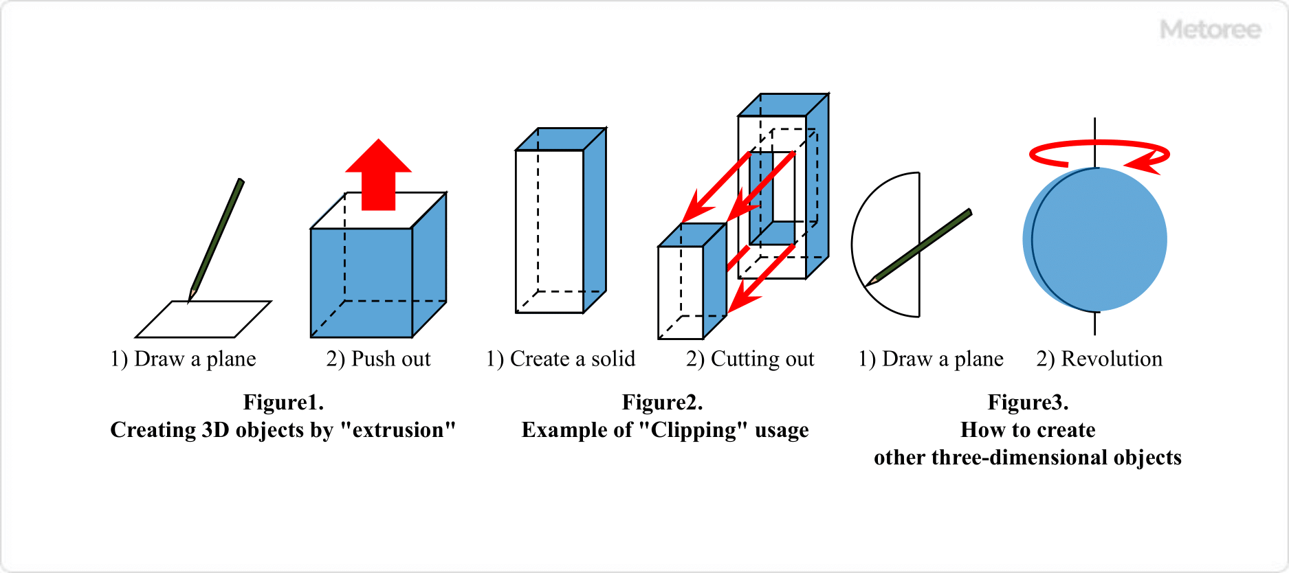
3D CAD, standing for “Computer Aided Design,” is a type of CAD software that enables users to create three-dimensional designs and models on a computer. There are two main types of CAD: 2D CAD and 3D CAD.

Uses of 3D CAD

3D CAD is categorized into architectural and mechanical types and further divided into high-end, mid-range, and low-end CAD based on functionality. The choice of CAD type depends on the specific needs and complexity of the design task.

1. High-end CAD

High-end CAD is used for complex designs involving numerous parts, such as in automotive and appliance manufacturing. Examples include CATIA, Creo Parametric (formerly Pro/ENGINEER), and NX. These systems offer advanced 3D modeling and extensive simulation functions.

2. Mid-Range CAD

Mid-range CAD is more affordable and user-friendly compared to high-end CAD, though it may have limited simulation capabilities. However, its core 3D modeling functions are robust, making it suitable for university research and simple product design. Examples include SolidWorks, Inventor, TopSolid, and Solid Edge.

3. Low-end CAD

Low-end CAD offers inexpensive or free options suitable for personal or hobbyist use. While adequate for basic design tasks, they may not be sufficient for complex geometries or multi-part assemblies. Examples include Inventor LT, 123d design, DesignSpark, and Creo Elements Direct Modeling Express.

Principles of 3D CAD

The fundamental steps to create a 3D model are consistent across different CAD software packages. The process typically involves selecting a plane, drawing a 2D sketch, and then extruding this sketch to create a three-dimensional object. Repeating the process of extrusion and cutting on different planes allows for the creation of the required 3D shape. Each CAD software may offer unique functions for model creation, so selecting the most suitable software for the specific application is important.

Other Information on 3D CAD

1. Situations in Which 3D CAD Is Used

3D CAD is particularly useful in scenarios where 2D design falls short, offering enhanced visibility, structural analysis, and clearance checks. It also enables the animation of designed parts to check their motion and range.

2. Advantages of 3D CAD

3D CAD allows for more intuitive modeling than 2D CAD, and design changes can be directly informed by analysis. It facilitates easier clearance checking in complex designs and enables rapid prototyping through CAM data or 3D printing. 3D models are also easily understandable, improving communication in large-scale, multi-departmental design projects.

3. 3D CAD User Engineer Examination

The 3D CAD User Engineer Examination certifies the knowledge and skills of engineers who use 3D CAD, ensuring proficiency in this advanced design tool.

カテゴリー
category_usa

2D CAD

What Is 2D CAD?

2D CAD
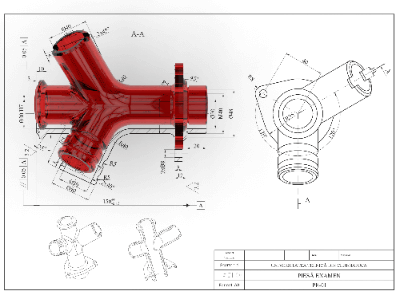
2D CAD is computer software that enables the creation, modification, and management of drawings. It has revolutionized the drafting process, previously done by hand, making it more efficient and manageable.

With the advancements in PC processing power and the affordability of printers, many manufacturing companies have adopted 2D CAD. This software has been developed for various industries, including machinery, architecture, civil engineering, and electrical wiring, often featuring industry-specific functions.

Uses of 2D CAD

2D CAD was initially used for drafting hand-drawn designs. Traditional hand-drawn drawings usually follow projection rules, displaying the product’s shape from multiple viewpoints, known as the first-angle or third-angle methods. However, with the advent of 3D models in the 2000s, design and manufacturing processes have evolved. While initiatives to combine 3D models and 2D drawings are underway in various industries, 2D drawings remain widely used.

Principle of 2D CAD

2D CAD operates similarly to general PC software, using a keyboard and mouse for input. It allows for the easy drawing of straight lines and curves of specified diameters. Autodesk’s AutoCAD is a well-known 2D CAD software with a significant market share. The use of the “dxf” file format ensures compatibility across different 2D CAD applications, facilitating data exchange between designers.

Other Information on 2D CAD

1. The Difference Between 2D CAD and 3D CAD

While 2D CAD represents objects in triangulation styles such as plan, front, and side views, 3D CAD allows for three-dimensional representation on a computer screen, with the flexibility to switch viewpoints. The transition from 2D to 3D CAD involves a different approach to drawing, where 3D models are created by extruding and modifying 2D drawings.

2. Reasons Why 2D CAD Will Not Go Away

Despite the increasing adoption of 3D CAD, many manufacturers still rely on 2D CAD. While 3D CAD offers comprehensive information, 2D CAD is simpler for adding instructions to drawings. The transition to 3D CAD also requires significant investment in equipment and training, and for manufacturing simple products like screws, the benefits of 3D CAD may be minimal.

カテゴリー
category_usa

Material Mixer

What Is a Material Mixer?

Material MixerA material mixer is a machine designed to mechanically stir two or more materials, which can be in solid, liquid, or gaseous states, using various agitating blades. This process aims to achieve the desired physical and chemical levels of mixing.

Material mixers come in two primary types: gravimetric (mass-based) and volumetric (volume-based).

The gravimetric mixer measures materials by mass during the mixing process, resulting in fewer errors related to the shape and size of the materials compared to volumetric mixers. Conversely, volumetric mixers determine the quantity of materials through screw feeding and timing, offering a more cost-effective solution than gravimetric mixers.

Uses of Material Mixers

Material mixers are versatile tools used in various industries, including pharmaceuticals, food, cosmetics, and chemicals. They are essential in the production of printing inks, colorants, paints, adhesives, sealants, toners, cosmetics, pharmaceuticals, rechargeable batteries, and more. These mixers are employed in settings ranging from large industrial plants to laboratories, handling diverse formulations.

Principle of Material Mixers

In material mixers, particularly when mixing solids like powders and granules, an external force is necessary since these materials do not self-diffuse as fluids do. The mixing tanks of these mixers are equipped with agitator blades such as butterfly, anchor, paddle, and turbine types. Multi-axis mixers, with both low-speed and high-speed shafts, are used to ensure thorough mixing, especially for materials that would otherwise flow unevenly with a single-shaft mixer.

For effective mixing, it’s crucial to maintain the materials in a fluidized (moving) state rather than a stationary state inside the equipment. However, the mixing process involves both homogenization and breakdown of materials, which can vary in intensity depending on the particle size distribution and specific gravity of the solids being mixed. Therefore, careful consideration of equipment design and operating conditions is necessary, tailored to the materials involved.

In some applications, a single-axis mixer, like a butterfly mixer, may be sufficient depending on the mixing requirements.