カテゴリー
category_usa

Configurator

What Is a Configurator?

A configurator is a tool or software used to set up or configure a machine, device, system, or software.

The term “configurator” is derived from the computer term “configure,” which means to configure or set up an environment. It is mainly used in the manufacturing industry to create product configurations by inputting specifications requested by customers.

In a product or service that has a very large number of combination patterns of optional elements and functional specifications, its optimal product configuration and reasonable parameter settings are calculated and selected according to the customer’s requirements.

After selecting specifications, a configurator’s system calculates possible combination patterns and their validity, and instantly derives a bill of materials and necessary estimates for the requested product.

The configurator has a general GUI that allows the user to configure the necessary settings and customize it to suit their business type.

Uses of Configurators

Configurators are mainly used in the manufacturing industry for estimating. In the automotive industry, they are called car configurators and are used to select specifications, options, and insurance for vehicles that are being considered for purchase.

Configurators allow the customer to select specifications and optional features from a range of specifications that the company can manufacture and support. In addition, the configurator can provide an accurate quotation for the specifications and optional features on the spot.

If there is no configurator at the sales meeting, the customer’s request must be brought back to the company, and inquiries must be made to the design and manufacturing departments, and a response compiled. On the other hand, with a configurator, the customer’s request can be calculated on the spot during negotiations, and negotiations can proceed while the quoted price is being presented. As a result, it is easy to significantly shorten the time required for sales and improve sales performance.

Principle of Configurator

Since configurators function as software, they must be preconfigured regarding the movement of the application, and there are two types of configuration methods.

1. Configuration by Configuration File

A file describing the configuration of the application behavior is created, and the application behavior is modified and configured by reading the file. The language of the source code of the configuration file depends on the system and application to be implemented, but in general, programming languages such as C, Java, Python, and Ruby are often used. 

2. Setting by a Screen in the Configurator

By creating a screen where the user can configure the settings, it is possible to customize the behavior of the application according to the user’s needs. In most cases, the default settings are used as a base, but screens that can be configured by the user can be built at the development stage to facilitate customization according to the intended use.

How to Select a Configurator

When selecting a configurator, the following points should be considered:

1. Is the Configurator Compatible With the Equipment to Be Used?

In some cases, the configurator may not be compatible with the type of equipment used. It is also necessary to confirm that the configurator is compatible not only with the device itself, but also with other devices and applications. 

2. Is It Easy to Operate?

Operability is very important for users who work with configurators. Even if the configurator has a full set of functions and is easy to customize, if it is difficult for the user to handle and understand, it will affect the efficiency of the business. Before introducing a configurator, it is necessary to confirm the operability of the actual product. 

3. Are Necessary Functions Installed?

Check whether the configurator is equipped with the functions necessary for the business. It is important that the configurator not only satisfies routine operations, but also has functions that can be used for non-routine operations.

4. Is There a Solid Support System?

We will check if there is a support desk that can be contacted in the event of a problem with the configurator. If there is a problem with the equipment that plays a key role in the core business of the configurator, it will have a significant impact on the business, so it is important to have a support system in place to ensure that the problem is handled promptly and accurately.
カテゴリー
category_usa

Clamp Meters

What Is a Clamp Meter?

A clamp meter is a measuring instrument designed to measure the current flowing through a cable by clamping onto the cable with a head that encloses it.

Unlike traditional methods that require direct connection to the circuit under test, a clamp meter has minimal impact on the circuit and can safely measure large currents. Typically, when measuring current in a wire or cable, the circuit must be disconnected, and an ammeter is inserted to measure the current.

However, this process can be cumbersome, which is why clamp meters are now commonly used for current measurements during electrical equipment inspections. In the past, analog models displayed measurements on a meter, but today, digital models that provide numerical readouts on a display have become the norm.

While clamp meters may offer additional functions like voltage and resistance measurement, this article will focus solely on current measurements.

Applications of Clamp Meters

Clamp meters find their primary use in measuring current during various electrical construction and inspection tasks in residential and commercial settings. The primary objective is to measure current in a cable without the need to cut the cable.

One significant advantage is that there is no need to disconnect the cable during measurements, allowing current measurements to be taken while lighting and equipment continue to operate as usual. Highly sensitive models can even measure minute currents, including leakage currents flowing from equipment to ground.

Principles of Clamp Meters

Clamp meters operate based on the principle of a transformer. The head that clamps onto the cable acts as the core of the transformer and is constructed from a highly permeable magnetic material (usually iron-based material such as Permalloy). A transformer can convert an alternating current on the primary side into voltage or current on the secondary side according to the turns ratio between the primary and secondary windings.

When a cable with current flowing through it is placed inside the core, it functions as the primary winding of the transformer. A coil equivalent to the secondary winding is also present in the head, allowing the current value to be measured and the current flowing in the cable to be calculated.

However, this method cannot measure DC current because no current flows in the secondary winding. For this reason, in AC/DC dual-use, clamp meters employ a head with a hall element embedded in the core. The hall element generates a voltage corresponding to the magnetic flux density, using the hall effect, for both DC and AC. This voltage is measured to calculate the current flowing through the cable.

Additional Information on Clamp Meters

How to Use Clamp Meters

1. Clamping Method

Using clamp meters is straightforward: simply clamp the cable between the heads. Placing the cable in the center of the head minimizes measurement errors, but slight deviations do not significantly affect accuracy.

2. Current Direction

When measuring DC current, pay attention to the direction of the current flow in the cable. Most clamp meters have symbols marked as “+” and “-“, indicating the current direction. Current flowing from “+” to “-” is considered a positive current value, while current flowing from “-” to “+” is negative.

3. Leakage Current Measurement

When measuring current in a device, either the outgoing or return cables pass through the clamp meter’s head. If leakage current is present within the equipment, some current will flow to the ground, resulting in a slightly lower current on the return path compared to the outgoing path.

This difference generates a magnetic flux density, which is displayed on the clamp meters and is equal to the magnitude of the leakage current. This principle allows for the measurement of equipment leakage currents. As these currents typically range from several mA to tens of mA, the clamp meters used should have a sensitivity of about 1 mA.

4. Accessories

When measuring currents in parallel cables with clamp meters, accessories such as line separators can be employed to separate the parallel cables, simplifying measurements. Additionally, using a wireless adapter that directly transfers measurement data to a PC via wireless communication is highly advantageous in preventing data transcription errors during fieldwork.

カテゴリー
category_usa

Catch Tanks

What Is a Catch Tank?

A catch tank is primarily used in internal combustion engines (gasoline and diesel engines).

In the field of motorsports, regulations often require its installation for safety reasons, and various companies offer aftermarket parts for this purpose.

Uses of Catch Tanks

During the combustion process of an engine, blow-by gases are typically reintroduced into the intake route, such as the intake manifold inlet, through the PCV valve.

However, this process also reintroduces oil mist and sludge generated inside the engine into the intake air. This can lead to oil burning at high loads and high RPM, resulting in white smoke. Additionally, the oil mist can contaminate the intake passage, causing the air cleaner to become oil-soaked, reducing intake efficiency, and causing oil to leak from the intake inlet.

To prevent these issues, catch tanks are installed in the engines of racing cars and other vehicles that heavily rely on high-revolution engines.

Principles of Catch Tanks

Catch Tanks can be broadly classified into two types: those with baffle plates inside and those without baffle plates. The former, known as a “separate type,” is characterized by the presence of a partition plate called a baffle, which separates the blow-by gas inlet pipe from the outlet pipe.

While the “separate type” separates gas and liquid by directing oil mist against the baffle plate, the latter type separates gas and liquid by extending the blow-by gas inlet pipe deeper than the outlet pipe.

However, the latter type may be susceptible to blockage of the blow-by gas inlet pipe due to oil accumulation, potentially causing an increase in crankcase pressure as blow-by gas loses its escape route. Therefore, it is necessary to drain the oil more frequently than with the separate type.

While general-purpose products are available from various manufacturers, it is essential to select the appropriate capacity based on engine displacement and oil volume requirements and securely attach it to a solid part of the engine or vehicle during installation.

カテゴリー
category_usa

Xenon Light Sources

What Is a Xenon Light Source?

Xenon Light Sources

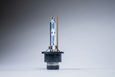
A xenon light source is an artificial light source that uses light emitted by an arc discharge in xenon gas.

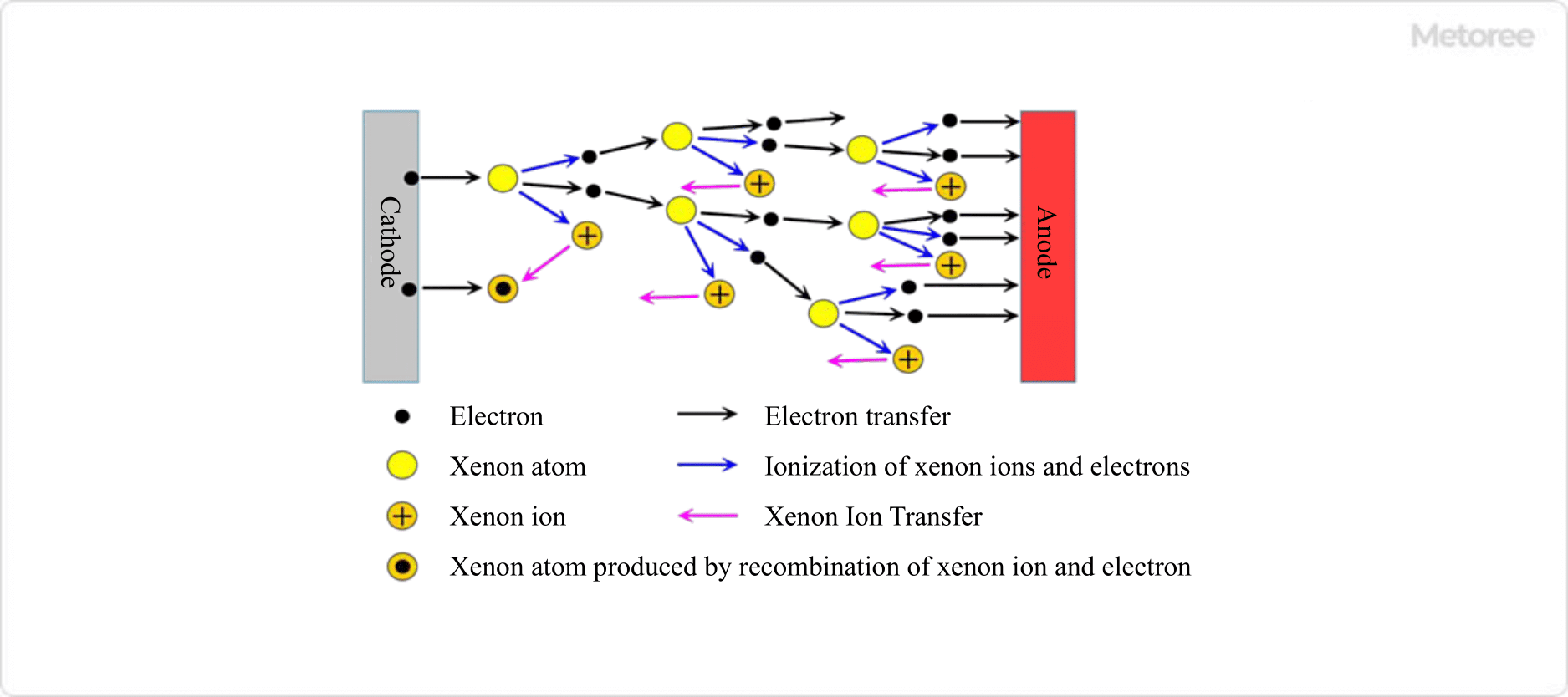
Arc discharge refers to the ionization of gas molecules between positive and negative electrodes, resulting in a plasma state, through which an electric current flows. Due to its luminescence principle, xenon light sources are characterized by lower power consumption and longer life than incandescent light sources that energize filaments such as incandescent lamps. Other major artificial light sources include halogen lamps, but xenon light sources are more powerful than halogen lamps and can irradiate smaller areas.

Xenon lights are sometimes referred to as xenon lamps, but this term is confusing with the term xenon-filled incandescent light bulb (xenon bulb), so this article will use the term xenon light source. A xenon light source that emits light by passing an electric current through a filament is completely different from a xenon light source that emits light by passing an electric current through plasmaized xenon gas.

Uses of Xenon Light Sources

Xenon light sources have a relatively long life because they do not heat a filament like incandescent light sources. Also, when combined with special filters, xenon light sources produce a spectrum that is almost identical to that of sunlight, making them useful in industrial, medical, and other fields where natural colors need to be reproduced.

1. Applications of Short-Arc Lamps

Xenon short-arc lamps are used as point light sources with high luminance in the following applications.

Illumination
Although they are used as high-luminance light sources such as searchlights and headlights, they are most frequently used for stage lighting and surgical lamps, where natural color reproduction is required. They are also used as light sources for endoscopes because of their compact size.

Light Source for Testing
As a solar simulator with properties similar to sunlight, it is ideal for testing the power generation efficiency of solar panels or conducting durability tests such as fading or degradation of materials due to sunlight. Because of its ability to output light of a wide range of wavelengths, it is used as a light source for spectroscopic analysis equipment, as well as for inspecting displays and measuring devices.

Light Source for Projection
Xenon short-arc lamps are the best choice for light sources for projectors, planetarium projectors, and large projectors, because in addition to being a point light source, they require stable output and high color rendering.

2. Applications of Long Arc Lamps

Xenon long-arc lamps are often used as large light sources that need to illuminate a wide area, such as floodlights in stadiums and aircraft guide lights at airports.

3. Flash Lamp Applications

Xenon flash lamps, which are most often seen, are flash lamps used for photography. They are used in large-sized flash lamps used in photo studios and other facilities, as well as flash lamps for SLR cameras.

Other applications include use as xenon light sources for treating burn scars and birthmarks by improving blood flow to the skin (to promote regeneration), and as light sources for IPL (Intense Pulse Light) hair removal.

Principle of Xenon Light Sources

3593_Xenon-Light-Sources_キセノン光源-1.png

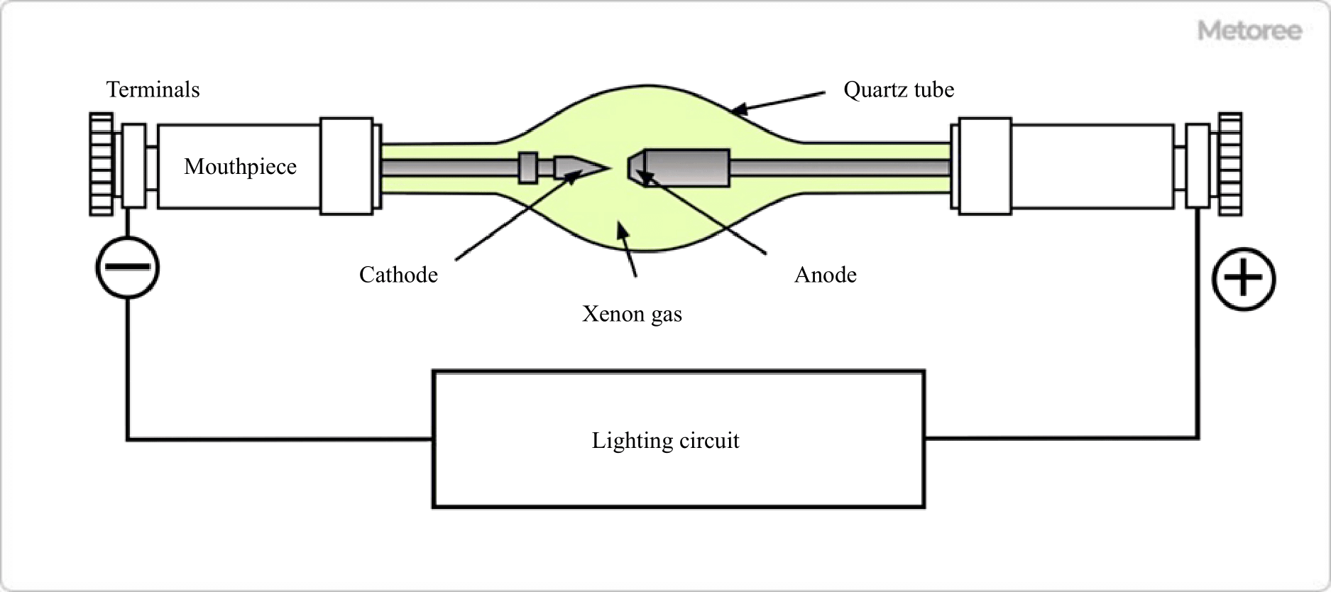
Figure 1. Arc discharge

The basic structure of a xenon light source consists of a quartz glass tube filled with xenon gas, two electrodes, and a lighting circuit connected to both electrodes from the outside of the glass tube. The role of the lighting circuit is to apply high-voltage pulses to the electrodes to cause dielectric breakdown, which initiates an arc discharge. Once initiated, the arc discharge can be sustained even if the applied voltage is lowered, so the rated voltage of most xenon light sources is 15 to 30 V.

3593_Xenon-Light-Sources_キセノン光源-2.png

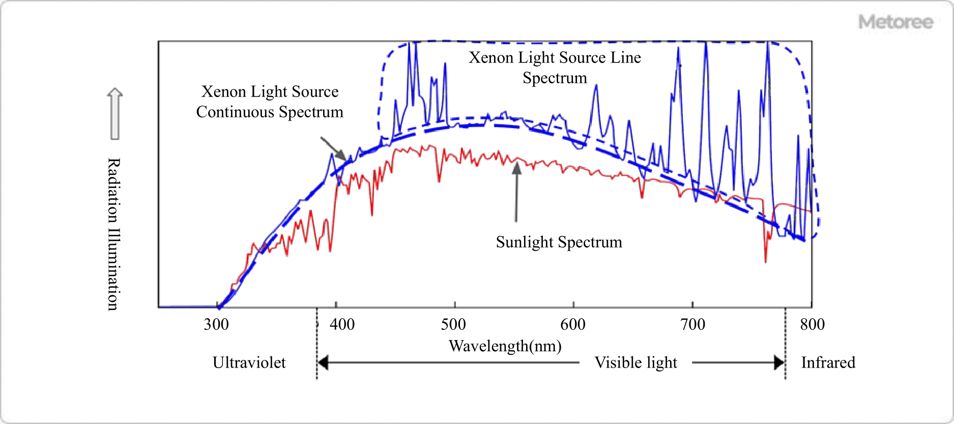
Figure 2. Spectra of xenon light source and sunlight

Some of the electrons in a xenon atom are excited without ionization, and when the excited electrons return to their ground state, they emit light at a specific wavelength (line spectrum). Therefore, the spectrum of a xenon light source is a continuous spectrum plus a line spectrum.

Types of Xenon Light Sources

Xenon light sources can be broadly classified into the following types

1. Short-Arc Lamps

3593_Xenon-Light-Sources_キセノン光源-3.png

Figure 3. Xenon short-arc lamp

Short-arc lamps have a short distance of less than a few millimeters between electrodes, making the emission area smaller than that of other xenon light sources and enabling the creation of a highly luminous point light source. The quartz glass tube is filled with xenon gas at high pressure (5 to 10 atmospheres) at room temperature. Xenon atoms emit light due to direct current discharge, and stable output can be obtained in a short period of time.

2. Long Arc Lamp

A long arc lamp consists of a long, narrow quartz glass tube filled with xenon gas at nearly one atmosphere (105 Pa). They are characterized by their extremely high luminous flux and usually have a rated power consumption of 1 kW or more; some lamps exceed 50 kW.

Generally, they emit light by alternating current discharge, and the distance between the electrodes is 5 to 10 cm or more.

3. Flash Lamp

A xenon light source that emits light for an extremely short period of time (several μs to several ms). Since the emission time is short, no cooling device is required, and the overall size can be reduced.

They come in a variety of shapes and are filled with 2 to 10 kPa of xenon gas. There are two types: a pulse voltage is applied at startup, and a shimmer method in which a weak current is constantly applied even when the light is not on to enable high-speed lighting.

カテゴリー
category_usa

Gas Cutting Torches

What Are Gas Cutting Torches?

Gas Cutting Torches

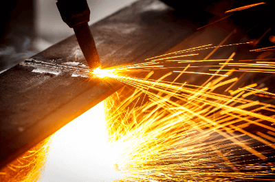
Gas cutting torches use combustible gases such as acetylene gas and highly concentrated oxygen to oxidize steel plates for cutting.

Because of the flashes of light that occur during gas cutting, a certain amount of safety equipment such as goggles and masks is required, and because flammable gases are used, care must be taken when handling the equipment.

Uses of Gas Cutting Torches

Basically, only steel materials can be cut by gas cutting. Gas cutting machines are used to cut medium to thick steel plates, which take a long time to cut with grinders and other machines.

One of the disadvantages of gas cutting torches is that they are generally hand-held, so they are not very precise.

There are also NC gas cutting torches that can program the cutting position and automatically cut complex shapes.

Principles of Gas Cutting Torches

Gas cutting torches are equipped with hoses that connect to acetylene and oxygen cylinders, and each gas is supplied from the cylinder. The two supplied gases are discharged from the crater at the tip of the gas cutter, one as a mixture of acetylene gas and oxygen for the preheating flame, and one as an oxygen-only gas.

When the gas for the preheating flame is ignited with a special lighter and brought close to the steel, the preheating flame raises the temperature of the steel to 800 to 900 degrees Celsius. As mentioned earlier, high-concentration oxygen is ejected from the center of the preheating flame, so the high-pitched steel material burns and becomes liquid when oxygen is supplied, and is blown away by the high-pressure oxygen. As these reactions occur one after another, the steel plate is cut.

The main advantage of gas cutting torches is that they can cut thicker steel plates than laser cutting.

Another advantage is that gas cutting torches do not require electricity; all that is needed is a gas cutting torch and a gas cylinder, thus reducing the amount of equipment required and making the process more portable.

カテゴリー
category_usa

Wedge Anchors

What Are Wedge Anchors?

Wedge Anchors

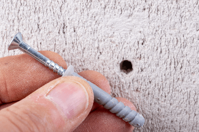
Wedge anchors are post-installation anchors used to attach objects to concrete base metal.

There are two types of anchors: pre-installed anchors and post-installed anchors. Pre-anchors are pre-installed in place before the concrete is poured, while post-anchors are drilled in place after the concrete has hardened.

Uses of Wedge Anchors

Wedge anchors are widely used mainly in the fields of construction and civil engineering.

As we can see in our daily lives, they are used to anchor storage sheds to concrete pavement to prevent them from tipping over, or to secure vending machines to the ground.

When fixing something to an existing concrete floor or block wall, unlike wood, it is not easy to process, and bolts and nuts cannot be used as is. Wedge anchors are used for this purpose. If the base material can be drilled, it can be easily secured.

Principles of Wedge Anchors

Wedge anchors are available in two types, the core rod type and the body type. Both types can be installed simply by hammering in the stepped part of the head or the top part of the body. Wedge anchors are easier to install than other products, which require a special hammering rod called a hammering punch for installation.

When holes are drilled, the wedge anchors are inserted into the hole, and the core rod or body of the wedge anchors is driven into the hole with a hammer. The outer circumference of the oar anchor swells inside the concrete, increasing its thickness. As a result, the gap between the wedge anchor and concrete is eliminated and it is fixed. The main body part of the wedge anchor protruding from the concrete has a male screw, so you can use a nut to fix things there.

Since the anchor is a post-construction anchor, it can be drilled and installed after the object to be fixed is set in place. This prevents problems caused by misalignment of the drilling position, such as “I drilled the holes in advance, but when I tried to install the equipment, they did not fit”.

カテゴリー
category_usa

Auto Levels

What Are Auto Levels?

Auto Levels

Auto levels are a type of surveying instrument that are installed on a level ground and used to check the level of the ground or buildings and measure height differences by looking through the lens.

A level that does not have an automatic function must be installed perfectly in relation to the ground and must be visually checked for levelness at the time of installation. This function allows for easy installation in a wide range of locations and eliminates the need to check the level during installation.

Applications of Auto Levels

Auto Levels are widely used in civil engineering and construction. The most popular use is to check the difference in elevation between two points when surveying land or roads.

When constructing buildings, they are used to check if the ground is level and to level it if necessary. A level that automatically reads the scale is called an electronic level.

A laser level, a type of Auto Level with reduced accuracy, is used not only to ensure the level by taking advantage of the straightness of the laser, but also to set the gradient and operate construction equipment.

Principles of Auto Levels

The most common principle of maintaining the levelness of Auto Levels is based on the characteristics of a pendulum.

When a level is placed on an unlevel ground, the scale viewed through the lens will be tilted as well if no correction is made. The Auto Levels utilize the property of a pendulum to always point in the vertical direction, and the scale display is suspended from the pendulum, so that the level is always corrected in the vertical direction within a certain range. To stop and stabilize the pendulum, an air brake system using a piston or cylinder, or a magnetic brake system using a magnet are used. The display format of the scale is generally optical.

The principle of an electronic level is the same as that of Auto Levels, but the scale is assigned on a bar code and the reading of the scale is automated by analyzing the image.

カテゴリー
category_usa

Ozone Water Generators

What Are Ozone Water Generators?

Ozone water generators generate low-concentration ozone in water from air, pure water, or oxygen gas.

Ozone has high oxidizing power and can be used to remove dirt, bacteria, and microorganisms, as well as to clean silicon wafers for semiconductors.

It is used in various industries such as medical, food, food and beverage, and semiconductor industries because the raw materials are inexpensive, metallic impurities are difficult to penetrate, operation is simple, and the system can be used immediately after start-up.

Applications of Ozone Water Generators

Ozone is a powerful oxidizing agent that can decompose compounds that cause contamination and remove germs and microorganisms.

Ozone water generators are therefore used in the food, food service, medical, and other industries to sterilize, deodorize, and remove sliminess.

In addition, by increasing the ozone concentration, it can not only decompose organic matter, but also remove metals and etch organic films, so it is also used in the semiconductor, liquid crystal, and solar cell industries.

Another reason why ozonized water is used in the semiconductor and liquid crystal industries is that it does not contain metallic impurities.

Principles of Ozone Water Generation

Water, water vapor, or oxygen gas is used as the raw material for ozone (O3). When water is used as a raw material, high voltage is applied to the water to cause electrolysis, which produces a small amount of ozone in the water. Normal water electrolysis produces oxygen and hydrogen, but by increasing the voltage, ozone can also be produced.

When oxygen gas is used as a raw material for ozone, a high voltage is applied to the oxygen gas. By applying high voltage, oxygen molecules (O2) are decomposed into oxygen atoms (O), and the decomposed oxygen atoms combine with oxygen molecules to produce ozone.

Features of Ozone Water Generators

Hydrochloric acid, ammonia, and other chemicals used in the semiconductor industry are relatively expensive due to their high purity.

On the other hand, the raw materials for ozonized water are pure water, oxygen gas, and air, so the cost is relatively low.

In addition, various types of ozone water generators are available for different applications, such as those that can change the ozone concentration or generate large amounts of ozone water.

Since ozone is a relatively unstable substance, it is not suitable for long-term storage. However, since the standby time between starting up the equipment and actually using it is short, this is not a problem when the equipment is actually used.

Uses of Ozone Water Generators in the Medical Industry

As mentioned above, ozone water generators are also used in the medical industry.

For example, they are used to remove viruses and bacteria. Usually, drugs are used to counter viruses, but the longer they are used, the more likely it is that new viruses resistant to the drugs will emerge.

Ozone, on the other hand, directly destroys the DNA of bacteria and viruses, making them less resistant and more suitable for pathogen removal.

In addition, the concentration of ozone contained in ozone water generators is very small and has no effect on the human body because it decomposes immediately after use and is converted into oxygen molecules.

Furthermore, since ozonated water contains only water, oxygen, and a small amount of ozone, it is easier and less expensive to dispose of wastewater after use than wastewater containing various chemicals.

Furthermore, since ozone water generators are easy to operate, they can be used on a daily basis by personnel with different expertise.

カテゴリー
category_usa

Expander

What Is an Expander?

An Expander is one of the tools used to join copper pipes, and it can expand the inside diameter of pipes.

When installing air conditioners, it is necessary to cut and weld refrigerant pipes. In this case, the expander is used to widen one of the pipes and insert the other pipe into it. By welding in this state, the strength of the joint can be maintained.

Of course, it is possible to weld without using this tool, but this tool is frequently used because it reduces the risk of gas leakage from pinholes.

Uses of Expander

A typical application for an expander is the installation of air conditioners.

Expanders are not often used in ordinary installation of air conditioners for home use because the piping is relatively thin and can be easily bent.

On the other hand, commercial air conditioners have thicker piping that is difficult to bend, so cutting and welding of the piping is almost indispensable for installation.

Expanders are routinely used for such work.

Various types of expanders, including hydraulic and rechargeable types, are available, and they can be used according to the size of the work area and the intended use.

Principles of Expander

Expanders consist of four main parts:

The first part is a roller that deforms the inner surface of the pipe.

The second component is the mandrel, which rotates the roller.

The third part is the frame, which prevents the roller from falling off.

The fourth part is the bearing collar, which prevents damage to the piping.

Various types of expanders are available, including rechargeable and hydraulic types.

Hydraulic expanders do not require recharging and are compact. They also require less hand fatigue because they do not require extra force during processing.

Rechargeable expanders are capable of speedy work. Also, since they do not require any force, they can reduce the burden on the operator even more than hydraulic expanders.

カテゴリー
category_usa

Air Pressure Regulators

What Is Air Pressure Regulators?

Air Pressure Regulators

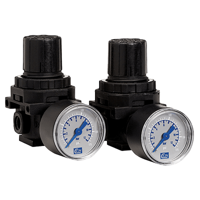
Air Pressure Regulators are devices used to reduce the pressure of compressed air created by air compressors from high to low pressure. The required air pressure is fixed for pneumatic power equipment. However, if you purchase an air compressor to match it, the cost will be very high. To eliminate that, we use air regulators to achieve multiple air pressures with one air compressor.

Air power is useful in places where electricity is difficult to use, such as explosion-proof environments.

Uses of Air Pressure Regulators

Air Pressure Regulators are used when the compressed air pressure obtained from an air compressor is high.

For example, an automatic ball valve uses an actuator to move the valve, and compressed air is sometimes used to power the actuator. At that time, an electric current is passed through the solenoid valve, and compressed air is sent according to the opening and closing of the solenoid valve.

The operating pressure range of the solenoid valve is about 0.3 to 0.7 MPa, and compressed air above 0.7 MPa must be depressurized.

Air Pressure Regulators are also used to operate machines and air blowers.

Principle of Air Pressure Regulators

Air Pressure Regulators can be set in the range of 0.05 to 0.85 MPa.

The pressure is regulated mainly by means of a spring, which is attached to a valve shaped like a globe valve in the middle of the supply route from the primary side to the A spring is attached to this valve (valve spring).

The secondary side also has a spring (regulating spring), and the spring is used to push the regulator from both the primary and secondary sides.

The pressure regulating spring can be adjusted by turning the handle attached to the Air Pressure Regulators. The pressure is adjusted by the balance between the force of the adjustment spring and the force of the secondary pressure with the diaphragm as the boundary. In other words, pushing in the adjusting screw to apply force to the adjusting spring will set the secondary pressure to match that force.

When the secondary pressure is lower than the set pressure, the valve spring is pushed and air flows into the secondary side; when the secondary pressure and the pressure of the regulating spring match, the balance is maintained and the valve section closes.