カテゴリー
category_es

Motores de Escobilla

¿Qué es un Motor de Escobilla?

Un motor de escobillas, también conocido como motor de corriente continua con escobillas, es un tipo de motor que utiliza contactos deslizantes llamados escobillas para llevar la corriente al eje giratorio.

Las escobillas también se utilizan en motores de corriente alterna con bobinado de alambre, pero el término motor de escobillas suele referirse a los motores de corriente continua con escobillas.

Se caracterizan por su construcción sencilla y barata y su fácil control del par. Sin embargo, las escobillas se desgastan con la rotación y requieren un mantenimiento regular. La desventaja es que generan ruido cuando se accionan.

Aplicaciones de los Motores de Escobilla

Los motores de escobillas se utilizan en una amplia gama de aplicaciones, desde productos de consumo hasta aplicaciones industriales. Algunos ejemplos típicos son:

  • Pequeños ventiladores de oficina y ventiladores de refrigeración de PC
  • Equipos industriales como extractores de calderas
  • Motores para trenes de cercanías
  • Motores de elevación de ascensores

Debido a su bajo coste entre los motores de corriente continua, se utilizan en ventiladores de refrigeración de equipos de oficina de corriente continua. También se han utilizado durante mucho tiempo en equipos móviles como trenes y ascensores debido a su fácil control del par y la velocidad de rotación.

En los últimos años, el control por inversor se ha convertido en la corriente dominante para el control del par en equipos móviles, ya que no requiere escobillas y es fácil de mantener. Los motores sin escobillas también son cada vez más populares.

Principio de los Motores de Escobilla

Los motores de escobillas están compuestos por tres componentes principales: el rotor, el estator y el conmutador. El estator puede estar formado por una bobina o por un imán permanente.

El estator genera un campo magnético constante, mientras que la corriente que fluye a través de la bobina, que está enrollada alrededor del rotor, interactúa con el campo magnético del estator, creando una fuerza electromagnética que hace girar el motor.

Es crucial que las escobillas estén en contacto con el conmutador y que la corriente de la bobina se dirija en una sola dirección para un funcionamiento correcto del motor.

El par y la velocidad del motor de escobillas pueden ser controlados ajustando la magnitud de la corriente que circula a través de la bobina.

Más Información sobre los Motores de Escobilla

1. Vida útil de los Motores de Escobilla

La vida útil de las escobillas de los motores de escobillas suele ser de varios cientos a varios miles de horas. Por otra parte, la vida útil del motor de escobillas viene determinada por la vida útil de los cojinetes y suele ser de decenas de miles a cientos de miles de horas.

Los motores de escobillas giran alternando las fuerzas de repulsión y atracción entre el estator y el rotor. Para que el rotor gire, la polaridad de la fuerza magnética debe conmutarse en función del ángulo de giro, de lo que se encarga el conmutador.

El motor puede accionarse simplemente aplicando una tensión continua, lo que lo hace sencillo de accionar y fácil de usar, pero las escobillas son contactos mecánicos que se desgastan debido a la rotación, por lo que si las escobillas no pueden sustituirse, la vida útil del motor es la vida útil de las escobillas.

2. Diferencia con los Motores sin Escobilla

Los motores de escobillas también se denominan motores de corriente continua porque pueden funcionar fácilmente con una fuente de alimentación de corriente continua. En cambio, los motores sin escobillas también se denominan motores síncronos de imanes permanentes. Los motores de escobillas son más fáciles de accionar y menos costosos que los motores sin escobillas, por lo que pueden utilizarse en una amplia gama de aplicaciones.

Los motores de escobillas se utilizan en muchas aplicaciones, pero su corta vida útil debido al desgaste de las escobillas es una desventaja. La sustitución de las escobillas es necesaria para un uso a largo plazo. Los motores de escobillas pueden controlarse mediante control de tensión continua, así como mediante impulsos PWM.

Los motores sin escobillas, en cambio, eliminan el conmutador y las escobillas y utilizan imanes permanentes en el rotor. La ausencia de escobillas se traduce en una mayor vida útil, y la vida útil de un motor sin escobillas es la vida útil de los rodamientos.

Los accionamientos de motores sin escobillas pueden clasificarse como “accionamientos de onda cuadrada” (es decir, accionados por una tensión de onda cuadrada) o “accionamientos de onda sinusoidal” (es decir, accionados por una tensión de onda sinusoidal). El accionamiento de onda cuadrada tiene un circuito de accionamiento relativamente sencillo y, por otro lado, genera ruido y vibraciones durante la rotación. En cambio, el accionamiento por onda sinusoidal tiene un circuito de accionamiento más complejo, pero se caracteriza por generar menos ruido y vibraciones durante la rotación.

カテゴリー
category_usa

Electropolishing Machine

What Is an Electropolishing Machine?

An electropolishing machine is a device used for electropolishing objects. It typically consists of a polishing tank and a power supply unit. The process involves placing an object in the polishing tank filled with a polishing solution, where a cathode plate is grounded, and an anode is connected to the object. By applying an electric current, electropolishing is performed, resulting in a range of benefits, including smooth and mirror-like surfaces and improved corrosion resistance.

Uses of Electropolishing Machines

Electropolishing is employed to achieve high smoothness and corrosion resistance, particularly for materials containing chromium. It is used in applications where high-purity and contamination-resistant materials are required, such as piping, storage containers, and parts used in semiconductor manufacturing facilities. Various industries, including pharmaceuticals, food manufacturing, medical equipment, chemical synthesis, and aerospace, utilize electropolishing to maintain clean and corrosion-resistant surfaces.

Principle of Electropolishing Machines

Electropolishing machines operate by applying a direct current between the cathode plate in the polishing tank and the anode of the object submerged in an electrolytic solution. The process involves dissolving the surface of the object electrochemically, with preferential dissolution of convex surface irregularities. Electropolishing effectively removes impurities, smoothens the surface, and forms a passive film on stainless steel, enhancing its corrosion resistance. It is a process that can be used to polish stainless steel and other materials to achieve a high level of surface smoothness and cleanliness.

Stainless Steel Surface Treatment by Electropolishing Machines

Stainless steel is a metallic material with rust corrosion resistance and heat resistance due to the several-nanometer-thick passive film formed on its surface by bonding with oxygen in the atmosphere. However, if the proper surface condition is not maintained through machining, surface finishing, transportation, storage, etc., the passivation film will not be formed uniformly, and excellent properties will not be obtained, resulting in defective products.

Electropolishing is a process that aims to cleanly remove impurities and roughness from the surface of stainless steel and form a passivation film with high properties. A stainless steel electropolishing machine electrochemically dissolves and cleans the surface down to the micron level by applying a direct current to the stainless steel being polished as an anode in an electropolishing solution. Electropolishing preferentially dissolves rough surface convexities, thus reducing surface roughness and smoothing out defects that are difficult to remove by normal polishing, such as burr coverings and voids created by polishing or machining. Even difficult defects can be smoothed out. In addition, the processing method is simple, and depending on the size of the electrolyte bath, it is possible to polish a large amount, so it is a polishing method with excellent productivity.

Electropolishing Machines

Electrolytic combined polishing, which combines physical polishing with abrasives, is effective when an even smoother surface than electropolishing is required. The passive film on the convex surface is mechanically removed and the metal is eluted from it, resulting in smoother polishing than when electrolytic polishing and mechanical polishing are performed separately. Because it can polish not only flat surfaces but also curved surfaces such as pipes, it is widely used for semiconductor manufacturing-related parts, piping, valves, and medical equipment that require precision and durability.

カテゴリー
category_usa

Electrolyte

What Is an Electrolyte?

Electrolyte
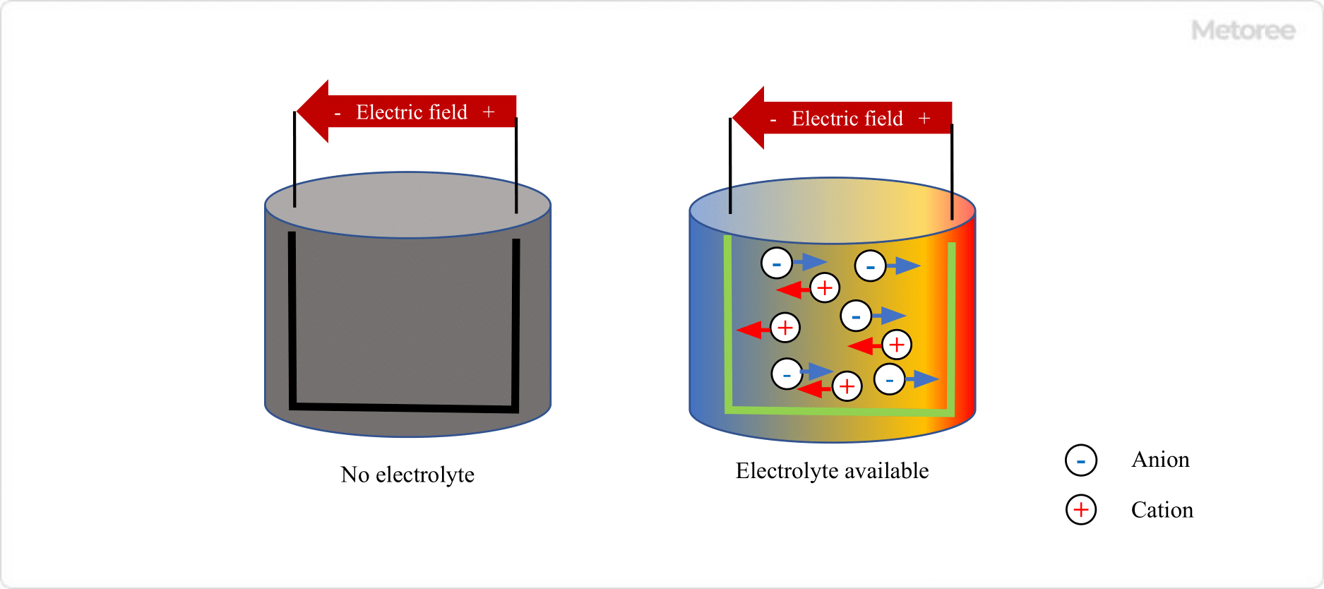
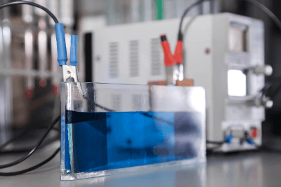
Electrolytes are liquids that contain dissolved electrolytes which allow electrical current to flow.

Electrolytes are dissolved as cations and anions, which can carry electric charges, thus electrolytes are ion conductive. Electrolytes are mainly used in storage devices, such as batteries and in plating.

In addition, although protic aqueous solvents are often used as electrolytes, non-protic solvents are commonly used in electrolytes for lithium-ion batteries.

Uses of Electrolytes

Electrolytes are used in a wide range of battery applications, whether for primary batteries or secondary batteries that can be charged and discharged. Specifically, electrolytes are used in lead-acid batteries, alkaline manganese batteries, nickel-metal hydride batteries, nickel-cadmium batteries, primary lithium batteries, secondary lithium-ion batteries, aluminum electrolytic capacitors, electric double layer capacitors, and lithium-ion capacitors.

Electrolytes are one of the materials that make up a battery, and a battery can generate electromotive force through chemical reactions at its electrodes. It is also an indispensable material for electrolysis to generate redox reactions on electrodes. In plating, it is a source of metal to be plated.

Principle of Electrolytes

_Electrolytes_電解液-1

Figure 1. Principle of electrolyte

Electrolytes are solutions containing dissolved electrolytes used in batteries and electrolysis. The electrolyte is ionized into cations and anions in a solution, and these ions act as charge carriers. The composition of electrolytes varies depending on the application, and the development of electrolytes with superior properties is constantly underway.

Generally speaking, electrolytes are for batteries. There are several types of electrolytes for batteries, and their composition varies greatly depending on the type of battery.

Types of Electrolytes

Electrolytes are important materials that are responsible for carrying the electric charge between the positive and negative electrodes of a battery, for example. The following is a description of electrolytes for each application.

1. Electrolytes for Lead-Acid Batteries

Lead-acid batteries use 30~35% dilute sulfuric acid as electrolytes. Lead-acid batteries use lead dioxide as the positive electrode and sponge lead as the negative electrode. When charging, the lead is converted to lead dioxide by passing current through the cathode, and converted to lead by passing current through the anode.

During discharge, lead dioxide from the positive electrode and lead from the negative electrode are dissolved in dilute sulfuric acid to produce electricity. Lead-acid batteries are used in automobiles, UPS (uninterruptible power supply), etc., and are widely used because they are inexpensive and easy to manufacture.

2. Electrolytes for Alkaline Batteries

Alkaline battery electrolytes are strongly alkaline aqueous solutions containing potassium hydroxide as the main component. Since the electrolytes of alkaline batteries are aqueous solutions, self-discharge occurs even when the batteries are not in use.

In the event of leakage, contact with the skin, or contact with the eyes, immediately rinse with large amounts of clean water and seek medical attention. Alkaline batteries are widely used as primary batteries and are suitable for long-term storage.

3. Electrolytes for Nickel-Metal Hydride Batteries

Concentrated potassium hydroxide solution is used as electrolytes for nickel-metal hydride batteries. Nickel-metal hydride batteries use a nickel oxide compound for the anode and a hydrogen storage alloy for the cathode. Nickel-metal hydride batteries have a high charge-discharge cycle performance and are used in hybrid cars and home appliances.

4. Electrolytes for Lithium-Ion Batteries

Organic electrolytes containing dissolved lithium salts such as LiBF4 (lithium tetrafluoroborate), LiPF6 (lithium hexafluorophosphate), and LiFSI (lithium bis-fluorosulfonyl imide) are used in lithium ion batteries. Electrolytes for batteries must not decompose during charging and discharging, not denature when heated, and not ignite when heated.

Lithium-ion batteries are lightweight, high-power, and long-lasting, and are used in smartphones, electric vehicles, and household storage batteries.

5. Electrolytes for Aluminum Electrolytic Capacitors

Electrolytes for aluminum electrolytic capacitors are made by dissolving salts of tertiary amines or amidines with carboxylic acids in solvents such as lactone or glycol. Aluminum electrolytic capacitors are used in a wide variety of products with electronic substrates in a wide range of fields, including the automotive, home appliance, and industrial equipment fields, because of their low cost.

6. Electrolytes for Electric Double-Layer Capacitors

Electrolytes for electric double-layer capacitors are made by dissolving electrolytes such as quaternary ammonium salts and imidazolium salts in organic solvents. A rechargeable battery is a capacitor that uses activated carbon as the active material for the positive and negative electrodes, and is suitable for applications that require a lot of energy. Where rapid charging and discharging is required and durability is required, electric double-layer capacitors are the capacitor of choice.

カテゴリー
category_usa

Power Supply Board

What Is a Power Supply Board?

Power circuits are essential in all electrical and electronic equipment. The power supply board is the form in which this power circuit is realized.

Instead of optimally designing this power supply board for each individual device, power supply modules in which power supply circuits made for general-purpose applications are implemented are often used, and since this is currently a very effective means, we will replace the power supply board with a power supply module.

A power supply circuit is designed to take 100 VAC commercial power as input and output the DC voltage required by the internal circuits. The DC voltage required by the internal circuits can be aggregated to 3.3V to 48V, depending on the equipment. Furthermore, the required current values can also be consolidated.

Therefore, if a power supply circuit that can supply more voltage and current than can be designed in-house exists as a complete module-type component, it will be of great value to utilize it.

The power supply module was born for this purpose. By narrowing down the specifications to a few types of power supply modules and producing them in large quantities, costs can be reduced, and high-performance modules can be designed because they are designed by engineers specializing in power supply circuit design.

Uses of Power Supply Boards

Power supply modules are used in a wide variety of equipment, including industrial equipment, information processing equipment such as computers and servers, home appliances such as TVs and refrigerators, and AV equipment such as recorders and audio components.

As various devices become more sophisticated and high-performance, and as devices become smaller, the installation space allowed for power supply circuits is becoming more and more limited, resulting in the need for smaller size, higher performance, and higher efficiency.

The need for dedicated power supply modules is increasing for these reasons, besides the potential cost savings compared to in-house design.

Principle of Power Supply Boards

There are two types of power supply modules: AC/DC power supply modules, which convert the aforementioned AC voltage to DC voltage, and DC/DC power supply modules, which boost or buck DC voltage.

AC/DC power supply modules take 100 VAC commercial power as the input and output, the specific DC voltage required by the internal circuitry of the equipment.

A DC/DC power module outputs a specified voltage by boosting or stepping down the voltage required by the internal circuitry after it has been converted to a DC voltage in the equipment.

In addition to simply converting AC to DC or DC voltage, many power supply modules have various built-in protection functions, such as overcurrent protection circuits and overvoltage protection circuits to prevent excessive current from flowing into internal circuits, and overcurrent protection circuits to prevent heating due to the amount of current flowing into the circuit. There are many power supply modules.

In addition, power supply circuits are strictly standardized according to various safety standards because incorrect use of the equipment can sometimes result in heat generation and ignition. Power supply modules generally comply with these various safety standards.

カテゴリー
category_usa

Power Control Unit

What Is a Power Control Unit?

A power control unit is a unit that controls the power supply of a system. It can also be a device that centralizes and controls several power supplies in a factory, building, etc. In either case, it still controls the power supply, which is the initial input to the system. In either case, the unit still controls the first input to the system, the power control unit.

In addition, some power control units are now equipped with general-purpose advanced functions, such as various types of communications, to enable communication with other systems.

Uses of Power Control Units

The range of applications for power control units is expanding. Conventional power control units, for example, are stabilized power supplies that can supply power even during power outages, such as UPS, or power supply units that control the power supply units of various products and systems, which are units whose main role is to supply power. However, with the recent digitalization and increase in the number of general-purpose products that use wireless technology, power control units are becoming mainstream, not only supplying power but also enabling communication with other systems using Wi-Fi or LAN.

Principle of Power Control Units

The principles of power control units vary widely depending on the scope of the device called power control units, but we will focus on the common point of controlling the power supply. Controlling the power supply means controlling the power supply. In other words, since the main role of a power supply is to input power from an external source such as a commercial power supply, and output electricity to the system to be supplied, it can be controlled by setting the power supply voltage, current, and frequency required for that system.

In addition, in the event of abnormalities such as overvoltage, overcurrent, lightning surges, or other hazardous noise input, the power control units have functions to protect the entire system by performing protective operations. Furthermore, with the recent evolution of the information society in the world, power control units, which control the power supply status of the entire system, are now equipped with external communication functions to enable system linkage through communication with other systems.

カテゴリー
category_usa

Voltage Amplifier

What Is a Voltage Amplifier?

Voltage amplifiers are devices that amplify the voltage of various electrical signals.

It is also sometimes called a voltage amplifier. A voltage amplifier is a circuit that amplifies an input voltage and outputs it, and is one of the basic components of an electronic device.

Uses of Voltage Amplifiers

Amplifiers are used when a small signal level is input and a larger signal is obtained as output. Since in many cases the input and output signals are voltage signals, devices for this purpose are called voltage amplifiers.

Voltage amplifiers are sold in a variety of forms and with different performance levels, depending on the purpose. The main applications include amplifying audio and video signals, as well as output signals from various sensors.

Principle of Voltage Amplifiers

The circuit configuration of a typical amplifier consists of an amplifying element (transistor, operational amplifier, etc.) and circuits to control it (bias circuit, feedback circuit, etc.). The voltage input to the amplifier element is amplified and output is at a high signal level.

The performance that is important depends on the purpose of use, and suitable circuits are proposed for each of them.

Types of Voltage Amplifiers

There are diverse types of voltage amplifiers on the market. Examples include audio amplifiers, high-frequency amplifiers, and measurement amplifiers.

These commercially available voltage amplifiers have different performance characteristics for various applications. It is important to select the appropriate performance index and use the appropriate voltage amplifiers for the environment in which they will be used.

1. Classification by Frequency

DC Amplifier
DC amplifiers are electronic devices used to amplify and process DC signals. DC amplifiers are used in a variety of applications, including amplification of sensor signals, DC motor control, and power management.

When selecting a DC amplifier, performance requirements, such as input signals, output signals, supply voltage, input impedance, output impedance, and frequency response, should be considered.

Low Frequency Amplifier (Audio Amplifier)
The most typical low-frequency amplifier is an audio amplifier. They are used in speakers, headphones, and other audio equipment to amplify audio signals. Major performance indicators include frequency response, distortion ratio, signal-to-noise ratio, and output power.

High-Frequency Amplifier
High-frequency amplifiers are used to amplify high-frequency signals. Specifically, they are used in wireless communications, satellite communications, and broadcasting. Major performance indicators include frequency bandwidth, gain, noise figure, and input/output impedance.

2. Classification by Function

Measuring Amplifiers
Measurement amplifiers are used to make high-precision measurements. Specifically, they amplify signals from sensors and instruments. Major performance indicators include amplification factor, input/output impedance, linearity, bandwidth, and noise figure.

Low Noise Amplifier
Low noise amplifiers have a low noise figure and are used in sensitive applications. Low noise amplifiers are used to amplify or process weak signals.

When selecting a low noise amplifier, it is important to check performance indicators such as noise figure, voltage gain, bandwidth, input voltage range, and power consumption. Note that low noise amplifiers may be used to reduce noise inside the equipment, and their resistance to noise outside the equipment is not guaranteed.

Differential Amplifier
A differential amplifier has two input terminals and one output terminal. By amplifying the difference between input signals, the effect of noise can be reduced and signal quality can be improved.

Particularly noteworthy performance indicators are PSRR and CMRR. These are very important items in canceling the effects of noise.

High-Voltage Amplifiers
High voltage amplifiers are a type of electronic component used to amplify and process high voltage signals. High voltage amplifiers are used in diverse fields, such as lasers, discharge devices, medical equipment, and industrial equipment.

When selecting high-voltage amplifiers, it is important to check performance indicators, such as output voltage, current, bandwidth, stability, and protection functions. Safety must also be considered, since they handle high voltages.

Other Information on Voltage Amplifiers

1. Characteristics of Voltage Amplifiers

Important indicators of amplifier performance include amplification factor, frequency response, distortion factor, input impedance, and output impedance. These performances are optimized by circuit design according to the intended use and are applicable to various applications.

2. Gain of Voltage Amplifiers

If the input signal of voltage amplifiers is Vin and the output signal is Vout, the gain is expressed as “Vout/Vin times” or “20log (Vout/Vin) dB.”

3. Current Supply Capability

Even voltage amplifiers can supply current to a load up to a certain range. However, voltage characteristics are basically prioritized, and a large current cannot flow, as in the case of power amplifiers.

カテゴリー
category_usa

Electric Torque Wrench

What Is an Electric Torque Wrench?

An electric torque wrench (nutrunner) is a tool capable of semi-automatic fastening of bolts and nuts with specified torque.

It plays the role of an electric socket wrench and an electric torque wrench at the same time. It can tighten bolts and nuts at high speed with the specified torque, thus dramatically improving the efficiency of work.

There are four main types of electric torque wrench: those that can set the torque applicable to the target bolt or nut, those that manage the tightening torque by angle, those that manually stop operation when the specified torque is reached, and those that automatically tighten to the temporary tightening torque and then manually tighten to the specified torque.

Uses of Electric Torque Wrenches

Electric torque wrenches are used on sites where work speed is required, as well as for high-torque fastening applications that are difficult to tighten manually.

For example, the specified torque for ISO 10-hole wheel nuts for large vehicles is as high as 600 Nm. In the case of 3-axle vehicles, 60 nuts must be tightened for 6 wheels, which is a considerable burden on the operator.

In addition, when constructing transmission line towers or wind turbines for wind power generation, the work is performed at high places, and there is a risk of losing balance and falling down.

Electric torque wrenches are equipped with a support mechanism that catches the reaction force and prevents stress from being generated in the part operated by the operator, thus enabling safe and efficient tightening to the specified torque.

Principle of Electric Torque Wrenches

Electric torque wrenches are suitable for nighttime work or work in residential areas because they do not generate impact noise like impact wrenches.

In addition, the low vibration of the wrench reduces the physical burden on the operator, and reduces the risk of vibration-induced carpal tunnel syndrome and carpal-arm vibration syndrome. The risk of developing noise-induced hearing loss is also reduced, contributing to the prevention of occupational accidents.

Some products can be connected to a computer to manage the work itself. By recording and storing data on “which bolts and nuts were tightened and at what torque,” it is possible to prevent accidents caused by forgetting to tighten them and to check the work procedures.

Although this system has many advantages, it has a disadvantage of limiting the size of the work area and storage space, because it requires the use of a wrench hanger with a damper to support lifting when using a large electric torque wrenches.

Small Electric Torque Wrenches

Small electric torque wrenches are often used hand held and are often battery rechargeable. The rechargeable type has the advantage of having no power cord, so there are no restrictions on work operation or placement. Also, many models have a function that allows wireless communication with a host for torque management, which is required for electric torque wrenches, and even battery-powered wrenches can transmit measured data and receive control signals. This function can also be used with corded models, allowing for centralized data management in the factory. In addition, the risk of running out of charge is reduced by using the same type of battery throughout the factory.

However, compared to electric and rechargeable impact drivers, these wrenches are larger, heavier, and have a lower rotation speed, so they must be used in different ways, depending on the application.

Torque Management of Electric Torque Wrenches

Electric torque wrenches operate by monitoring the torque, angle, and speed changes during tightening.

The records can be stored in the electric torque wrenches itself or wirelessly transferred to a host for management as assembly result data. These functions can also be used to determine if a bolt is tightened properly. For example, this is because the torque data can detect such problems as diagonal tightening where bolts are inserted at an angle, omitted insertion of washers, and double insertion.

In addition, the advanced models can detect the posture and position of the electric torque wrenches, determine the position of the screw tightening hole, and determine whether the screw or bolt being tightened matches the specified one or not. The tightening torque can be automatically changed by determining the screw or bolt specification from the screw hole position.

Sockets for Electric Torque Wrenches

Sockets used with electric torque wrenches are sold exclusively by each electric torque wrench manufacturer. Basically, the same sockets for general-purpose socket wrenches or impact wrenches can be used. From the viewpoint of torque management, it is necessary to use sockets with high mounting accuracy.

カテゴリー
category_usa

Electric Gripper

What Is an Electric Gripper?

A gripper is a mechanism for grasping and holding an object. Among these, an electric gripper is a device that is driven electrically and grips an object.

The shape of the gripper varies depending on the shape and surface properties of the object to be gripped. The most commonly used gripper is the two-finger parallel gripper, in which two parallel members move in a linear motion to clamp and release the object. They are used as devices (end-effectors) that function at the end of robot arms and linear motion mechanisms.

Compared to pneumatic grippers, electric grippers offer more precise control and are used when the size of the object varies or when the gripping force needs to be varied as necessary.

Uses of Electric Grippers

As mentioned above, there are various types of grippers, but here we will discuss the most common type, the two-finger parallel electric grippers.

Since electric grippers can grasp and transport objects, they are used in equipment that lifts and transports objects by combining them with linear motion mechanisms such as cylinders and linear guides. Moreover, by attaching an electric gripper to the end of a robot arm, it is possible to move an object freely in three dimensions, just like a person holding an object.

Principle of Electric Grippers

Electric grippers mainly consist of a finger (sometimes called a claw) for gripping an object, a linear motion mechanism such as a feed screw for moving the finger, and a motor for operating this mechanism. A sensor such as a load cell may be separately incorporated to control the gripping force.

The opening and closing motion can be controlled by controlling the direction and speed of rotation of the motor, and the width of opening and closing can be fed back by reading the number of rotations from the rotary encoder built into the motor. By constructing process control or PID control according to this information, precise control can be achieved, such as slowing down the gripping speed at the moment of contact with the object or setting the distance between the fingers when gripping according to the size of the object.

In the robotics field, however, grippers with three or more fingers are often used to grasp more complex shapes or to learn human motions. Because grippers with three or more fingers require precise control, such as mimicking human motion, most grippers are electric grippers.

カテゴリー
category_usa

Waterproof Screw

What Is a Waterproof Screw?

Waterproof Screw

A waterproof screw has a waterproof shield ring attached to the seating surface (behind the head of the screw) to block water leakage.

Since there is a small gap between the screw’s seating surface and the object to be fastened, it is an easy entry path for water and organic solvents. The shield ring of a waterproof screw is highly water-resistant and airtight, and can close the gap between the seating surface and the object to be fastened. This is why they are used to protect electronic circuit boards in home appliances from water splashes and to prevent rainwater from penetrating machinery used outdoors.

Uses of Waterproof Screws

Waterproof screws are used to protect precision instruments and water-sensitive equipment from water immersion.

In particular, waterproof screws are indispensable for the following equipment:

  • Precision equipment vulnerable to water immersion (personal computers, measuring instruments, medical equipment)
  • Equipment used outdoors (weather instruments, solar power generation equipment)
  • Equipment intended to be used in places where water is splashed (dishwashers)

If waterproof packing and screws are purchased separately, the size may not fit or the seal may be weak. Therefore, waterproof screws with a set of waterproof shielding rings are used.

Principle of Waterproof Screws

Waterproof screws are designed to be exposed to water, so the main body (screw part) is made of rust-resistant SUS. A waterproof shield ring that matches the size of the body is attached to the seat (back side of the head), which serves to seal the gap between the screw and the object to be fastened.

The shield ring is generally made of nitrile rubber (synthesized by polymerization of acrylothrin and 1,2-butadiene). Nitrile rubber can withstand solvents such as gasoline and alcohol as well as water, and can be used to prevent the penetration of oil and grease. However, it is corroded by ethyl acetate and ether, so if resistance to these organic solvents is required, use fluoroplastic (PTFE).

The procedure for using waterproof screws is as follows:

  1. Make sure the shield ring and screw diameters match (they are usually sold as a set, so the diameters will match).
  2. Fit the shield ring on the seat surface and push it in securely all the way to the back.
  3. Pass the shield ring through the object to be fastened to prevent it from coming off. In the case of a bolt type, secure it with a washer and nut.

This will seal the gap between the seat and the object to be fastened with the shield ring, preventing water from entering the equipment.

Main Materials and Surface Treatments of Waterproof Screws

The main material used for waterproof screws are stainless steel.
As described in the section on proper use, the tightening torque should be carefully selected to obtain sufficient tightening due to the presence of the shield ring. Particularly when designing equipment where human lives are at stake, sufficient consideration should be given.

Electrical corrosion is also an important factor. If the material of the waterproof screws differs from the material of the mating mechanical element or the object to be fixed, a difference in metal potential may result in corrosion. Particular attention should be paid to aluminum and stainless steel.

The surface treatment of waterproof screws should be selected according to the corrosion countermeasures against electric corrosion mentioned above, the quality of appearance, and the price.

Proper Use of Waterproof Screws

Waterproof screws are basically intended for use in areas that are exposed to water, such as external covers. If not used properly, the mating nut may be damaged, or the product or equipment assembled with the waterproof screws may be damaged.

To prevent this, the basic approach is as follows:

  1. The tightening force must be within the allowable range so that the waterproof screws (especially the shield ring) and the mating member will not break.
  2. The repetitive force (due to vibration, etc.) applied to the waterproof screws and the mating material must be within the allowable range.
  3. The seating surface of the waterproof screws (the surface that contacts each other, not the surface that the tool touches) must be within the allowable range. The pressure exerted on the seating surface of the waterproof screws (the surface that contacts each other, not the surface that the tool touches) shall not cause the object to be tightened (metal, wood, etc.) to cave in.
  4. The object to be fastened shall not be broken by fastening waterproof screws.

Loosening of Waterproof Screws

Even if waterproof screws are used properly, gradual loosening of waterproof screws can cause the object to be fastened to become dislodged, which may lead to a serious accident involving human life, depending on the object to be fastened.

Loosening can be caused by the following two factors:

  • Repeated vibration applied to the waterproof screws
  • Repeated heat generation to the waterproof screws from the outside air temperature or from the object itself to which it is fastened.

Tightening waterproof screws strongly is effective in preventing loosening, but it can also cause waterproof screws to break or destroy the screw holes. Especially when designing equipment that involves human life, it is necessary to calculate the allowable range of tightening force, as described in the section on proper use of waterproof screws.

When retightening screws in purchased products, if there is already a defined tightening force regulation, it is sufficient to tighten the screws accordingly.

Another method to prevent loosening is to use a loosening adhesive.

Since the principle of anti-looseness is friction, it is actually difficult to guarantee that it will never loosen. Sufficient testing is also something to consider.

カテゴリー
category_usa

Rebar Detector

What Is a Rebar Detector?

A rebar detector is a device that measures the rebar, water pipes, electrical wiring, etc., inside concrete. It is used to check the structure and construction condition of a building and to confirm whether wiring has been cut or not. If the rebar is not well connected or the wiring is not in the proper position, it could cause an accident. Inspection with a rebar detector is a very important process. It is a non-destructive way to check the inside of a structure without damaging the structure. There are two main inspection methods: the electromagnetic radar method and the electromagnetic induction method.

Uses of Rebar Detectors

Rebar detectors are used to measure the thickness of the rebar and its covering in concrete buildings. These include buildings, condominiums, and other structures, as well as ground and highways made of concrete. In addition to reinforcing bars, other items buried in concrete include water pipes, gas pipes, and electrical wiring. When constructing a building, rebar detectors are used to check for defects in the rebar and identify structural flaws. They are also used to check the internal conditions during the installation of electrical and gas piping and air conditioning equipment.

Principle of Rebar Detectors

There are two types of rebar detectors based on different measurement principles.

  • Electromagnetic Wave Radar Method
    This method uses electromagnetic waves to examine the interior of concrete. This type of rebar detector is equipped with a transmitting antenna to send electromagnetic waves and a receiving antenna to receive them. When electromagnetic waves are sent toward the concrete, they travel inside and are reflected by the rebar and wiring. The position and size of objects inside can be determined from the time it takes to receive the waves, including this reflection. In addition, many rebar detectors of the electromagnetic radar method are driven type with wheels, and measurement can be made while moving the surface of the concrete to enable more three-dimensional measurement.
  • Electromagnetic Induction Method
    This method uses the principle of electromagnetic induction to examine the interior of concrete. First, a magnetic field is generated by passing an alternating current through a coil. The principle of electromagnetic induction causes an electric current to flow through the rebar, generating a magnetic flux. By detecting this change, it is possible to check the inside of the concrete. Although this method is capable of accurate and precise measurement, errors may occur if multiple magnetic materials are included in the magnetic field.