カテゴリー
category_usa

Optical Modulator

What Is an Optical Modulator?

An optical modulator is a device used for high-speed modulation applications by converting an electrical signal into an optical signal for output.

Also called an E/O converter (or O/E converter for the reverse conversion), it is mainly used as part of an optical transmission device in fiber-optic communications. In conventional systems, the signal used to transmit modulated signal information is always an electrical signal.

However, in order to realize optical communications using ultrahigh-speed, low-loss, high-capacity optical fiber, electrical signals must generally be used in some way to modulate the light source and output as an optical signal. The device that plays this role is an optical modulator.

Uses of Optical Modulators

Optical modulators are mainly used as modulators to convert the modulation of electrical signals in fiber-optic communication. They play an extremely important role in optical fiber communications, which are now the foundation of information transmission.

Fiber-optic communication is an optical communication method that enables high-speed and long-distance transmission by using low-loss, wide-bandwidth optical fiber for communication lines instead of ordinary electric wires, which have high loss and are susceptible to noise. To introduce this method, a device capable of fluidly exchanging electrical and optical signals is required, and an optical modulator is used.

Principle of Optical Modulators

The principle of light modulation includes the “direct modulation method,” which uses light modulated by directly turning on and off the electrical bias of a semiconductor laser used as the light source, and the “external modulation method,” which modulates light from a semiconductor laser using an LN (LiNbO3: lithium niobate) modulator, etc. There are two types of modulation methods.

1. Direct Modulation Method

The direct modulation method is a method in which the light source, the semiconductor laser itself, modulates the optical signal. However, the response speed of the semiconductor laser itself is limited and causes wavelength fluctuations called “chirping,” so this method is not suitable for high-capacity optical fiber communications for trunk lines, where high speed is required.

2. External Modulation Method

In the external modulation method, a semiconductor laser, which is the light source, continuously outputs light of a constant wavelength. This light is input to an optical modulator, such as an LN modulator, and the amplitude and phase of the light are changed by an external electrical signal. The principle behind this is that the electrical signal is output as modulated light.

Generally, optical modulators are modulators used in this external modulation method. The method of converting electrical ON/OFF modulation into optical ON/OFF requires high-speed changes in the amplitude and phase of light, and for this purpose, physical phenomena such as light interference and electric field absorption are utilized.

Specifically, there are field-absorption (EA-type) optical modulators and Mach-Zehnder-type LN modulators. LN modulators, which are often used in high-capacity trunk line optical communications, have Y-shaped distributed optical waveguides, and by applying a bias to the waveguide and inducing a phase shift of the light, the intensity of the light passing through the LN modulator can be increased or decreased.

This method is very suitable for high-capacity, high-speed optical fiber communications because it does not, in principle, cause the chirping (wavelength fluctuation) of the direct modulation method.

Other Information on Optical Modulators

1. DC Drift Compensation of LN Modulators

LN modulators are characterized by low loss, and low chirping due to their Mach-Zehnder interference principle. However, they are subject to optical output drift variation due to temperature change and DC drift.

For this reason, manufacturers of LN modulators usually support dedicated bias controllers for LN modulators that automatically correct DC bias based on feedback information from PDs and other devices.

2. Material Innovation of Optical Modulators

Although LN modulators can suppress wavelength fluctuation extremely well compared to field absorption and direct modulation methods, their drive voltage is relatively large at around 5 V and their size is relatively large (50 mm or more), so development toward smaller size and lower power consumption is continuously being promoted.

Recently, research and development is being actively conducted by research institutes of various manufacturers to compensate for the weak points of LN modulators, such as optical waveguides formed in a ring shape on a silicon substrate, known as silicon photonics, and MQW (multiple quantum well) optical waveguides on an InP compound semiconductor.

In addition, research and development of optoelectronic fusion technology at NTT’s IWON, which actively handles optical signals as light inside the IC without an E/O converter, is also being actively pursued for even higher capacity communications in the future.

カテゴリー
category_usa

Drawing Software

What Is Drawing Software?

Drawing Software

Drawing software is a computer application used for creating shapes, graphs, and other visual elements. It features an intuitive interface with functionalities like shape drawing, straightness and curves, text addition, color setting, shape grouping, layer management, and file exporting. Advanced software may also support animation.

This software is instrumental in visually representing ideas and data, enabling precise measurements and accurate graphics creation.

Uses of Drawing Software

Drawing software is versatile, catering to both professional and personal use. Its applications include:

1. Design

Used for creating logos, posters, and graphic designs. It’s instrumental in combining graphics and illustrations for attractive designs and in generating graphs and charts for presentations and reports.

2. Architectural Drawings

In architecture and engineering, it’s used to create detailed, dimensionally accurate drawings and maps for visual geographic information representation.

3. Process and Project Management

Helpful in creating flowcharts and diagrams for process visualization and information organization. It also aids in making Gantt charts and flowcharts for task scheduling and resource allocation.

Principle of Drawing Software

Drawing software operates on algorithms and data structures for shape and graph creation and display. It uses 2D or 3D coordinate systems for shape representation, with transformations performed via vector operations. The software manages shapes and elements through layers and objects, using hierarchical structures for efficient viewing and editing.

Types of Drawing Software

Drawing software ranges from basic shape drawing to advanced design and technical functionalities:

1. Vector Type

Vector-type software, like Adobe Illustrator and CorelDRAW, creates shapes in vector format.

2. Raster Type

Raster-type software, such as Adobe Photoshop and GIMP, creates images in pixel units.

3. CAD (Computer-Aided Design) Software

Specialized for engineering and architectural use, CAD software like AutoCAD and jw_cad focuses on precise 3D modeling and blueprinting for detailed design and construction project drawings. jw_cad is a free, 2D general-purpose CAD software popular for architectural design.

カテゴリー
category_usa

Wire Harness

What Is a Wire Harness?

Wire Harnesses

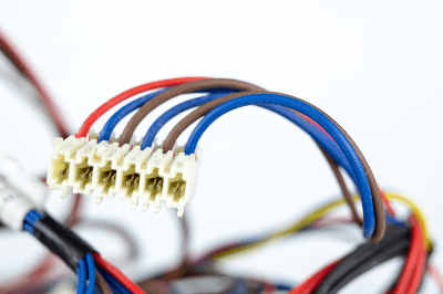
A wire harness is a general term for a group of parts that are responsible for the connection between devices and that are bundled together with electric wires, terminals, and connectors attached to both ends of the wires to transmit various electric signals emitted from the devices.

Because multiple electric wires are necessary for the number of signals to be transmitted, and because the thickness and flexibility of the wires vary depending on the intended use and the size of the current flowing through them, they can be compared to “blood vessels” in human terms in terms of their function.

The most typical use of wire harnesses is in automobile wiring harnesses. Wiring harnesses are used around the engine, where the lead-acid batteries and other components that supply electricity to the car are mainly located, as well as around the driver’s seat, rear tail lights, and other areas of the car.

Recently, with the widespread use of hybrid and electric vehicles, there is a growing demand for products that are lighter and can withstand higher voltages, and the development of products with particularly high voltage resistance is underway.

Uses of Wire Harnesses

Wire harnesses are used to connect devices and equipment to transmit electrical signals from one to the other. Wire harnesses are also used in many other fields besides automobiles. Examples of applications are as follows:

1. Automobiles

The most typical use of wire harnesses is in automobiles. They are concentrated around the engine, which is the main power source. Starting from the engine periphery, they are connected to all parts of the automobile, including the air conditioner control panel located inside the automobile, and the brakes and rear tail lights located outside the automobile.

For ease of assembly and maintenance, the wiring harnesses are not connected by a single long wire but are divided into sections, such as “front, middle, and rear,” and are installed in the car. The connections between the divided wire harnesses are generally made via connectors.

In addition to engine applications, harnesses for sliding doors also exist. Sliding door applications are designed for smaller sizes and mobility.

2. Medical Equipment

Harnesses are also used inside medical equipment such as MRIs and CTs. Compared to automotive applications, where the wire harness itself has to pass through the limited space inside the vehicle while considering vibration and water damage, the shape of the wire harness itself is simple.

Instead, the reliability of information between connected devices is required, so the required performance in terms of noise reduction and electrical resistance tends to be high.

3. Production Facilities

Wire harnesses are also used in equipment used to produce electrical appliances and other products. Production lines in factories are long and are expected to be used for a long period, and in some cases, production lines are relocated, so long wire harnesses are often used.

In addition, wire harnesses are often trampled by both workers and heavy machinery in factories, and are often contaminated with oil and dirt, so high durability of wire harnesses tends to be required.

Types of Wire Harnesses

There are different types of wire harnesses, ranging from low-voltage wire harnesses for general applications to high-voltage wire harnesses for high voltage applications.

1. Low-voltage wire Harnesses

Low-voltage wire harnesses are used to supply power from the 12V lead-acid batteries used in conventional gasoline-powered vehicles to various components.

2. High-Voltage Wire Harness

High-voltage wire harnesses are wire harnesses for use in electric and hybrid vehicles, which have been in increasing demand in recent years.

Motors are used to drive electric and hybrid vehicles, which require high power output to drive the motors. In addition, the control unique to electric and hybrid vehicles, such as using the motor as a generator during deceleration to charge the battery with regenerative energy to extend the cruising distance, requires higher heat resistance performance to withstand more complex system control.

Therefore, conventional wire harnesses cannot withstand high voltages and large currents, and high-voltage wire harnesses have been developed.

3. Aluminum Wire Harnesses

Aluminum wire harnesses are wire harnesses in which the conductor of the wires has been changed from conventional copper to aluminum.

Although it is expected to be 30~40% lighter than conventional copper, it has lower electrical conductivity and lower melting point than copper and thus has issues with heat resistance and the processability of crimp terminals attached to the terminals.

As the number of wire harnesses increases with the improvement of automobile safety and comfort, and with the shift to automated driving, there is concern that the weight of the car body will increase, and the demand for lightweight aluminum wire harnesses is increasing.

Principles of Wire Harnesses

Wire harnesses consist mainly of corrugated tubes, clips, connectors, terminals, wires, and tapes.

1. Corrugated Tubing

A corrugated tube is a bellows-shaped tube used as a protective material for wire harnesses. Since it is mainly used to protect electric wires, heat resistance, and shape restoration properties are required.

There are two types, one with slits and the other without slits, for ease of processing during installation, so it is necessary to select one according to the need. Polypropylene resin is often used as a material.

2. Clips

Clips are used to secure wires when crawling wire harnesses. Various types exist according to the size and shape of the harness.

3. Connectors

Connectors are used to connect electrical wiring. Generally, male and female connectors come as a set. By crimping dedicated terminals onto stripped wires and inserting them into connectors, connections can be made easily without soldering or twisting wires together.

4. Terminal

Terminals are attached to the ends of wires. Like connectors, terminals also come in male and female sets and are used to connect wires by touching the terminals when connecting to a connector.
Generally, wires and terminals are joined by crimping.

5. Electric Wire

Wires are used to supply electric power and transmit electrical signals to connected devices. Copper is mainly used for wires because of its good balance of price and conductivity, but the number of wires used in wire harnesses is expected to increase in the future as systems become more complex. As a result, there is a growing demand for lighter weight wires themselves, and the development of aluminum wires is underway.

6. Tape

Tape is used to restrain electric wires and protect insulated parts. Since wire harnesses require insulation and flame retardance, vinyl tape made of vinyl chloride is mainly used.

Other Information on Wire Harnesses

1. About Wire Harnesses Factories

The manufacturing of wire harnesses involves many processes that are carried out by hand, so full automation of production is less advanced than in other manufacturing industries. For this reason, production is often carried out in countries with low labor costs, and the ratio of female employees, who are suited to light work, tends to be high.

2. The Future of Wire Harnesses

The future of wire harnesses is expected to shift from conventional wire harnesses to high-voltage wire harnesses for electric vehicles and lightweight aluminum wire harnesses.

カテゴリー
category_usa

Rotary Blower

What Is a Rotary Blower?

A rotary blower is a type of positive displacement pump that functions as a pump by rotating a rotor eccentrically mounted inside a casing.

Roots blowers are similar to rotary blowers in that they function as pumps by rotating a cocoon-shaped root, but there is a gap between the roots and the casing, so a high compression ratio cannot be obtained.

However, rotary blowers have a higher compression ratio than Root blowers because there is no gap between the rotary blower and the casing.

Uses of Rotary Blowers

Because rotary blowers can discharge large volumes of gas at high pressure, they are often used as blowers for aeration tanks in septic tanks and wastewater treatment facilities, where large volumes of air are required.

They are also used as pneumatic conveying blowers for the same reason.

They can also be used as vacuum pumps because of the contact between the rotor and casing. Today, they can also be used for suction-type filtration equipment and as a vacuum pump for vacuum equipment and suction-type pneumatic conveying.

In addition, rotary blowers are also used for mixing mixtures of mixtures and in various chemical industries.

Principles of Rotary Blowers

Rotary blowers have an eccentric rotor mounted inside a casing. The rotor has a cylinder attached to it that moves up and down, maintaining contact with the rotor by moving up and down as it rotates.

Because of this structure, rotary blowers can maintain a high compression ratio at all times, thus producing high pressure. Likewise, they can also demonstrate high performance as vacuum pumps.

However, since there are inevitably parts that come into contact with the pump, it is necessary to constantly supply oil to the inside of the pump for lubrication.

Therefore, a mechanism to separate the oil at the discharge side was necessary, and it could not be used for equipment for which the presence of oil might be hazardous.

However, oil-free rotary blowers are now available, so they can be used in facilities that do not tolerate oil. There are also rotary blowers that support special specifications for internal coating, etc., so they are used in many industries, including the chemical industry.

カテゴリー
category_usa

Rotary Connector

What Is a Rotary Connector?

Rotary Connectors

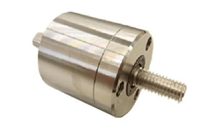
Rotary connectors facilitate electrical connections between rotating and stationary components. They are crucial for powering rotating parts or transmitting signals and data from sensors on rotating parts to stationary control units.

Commonly, rotary connectors contain liquid metal, such as mercury or gallium alloys, to maintain conductivity. They find application across diverse fields including industrial machinery, automotive, medical equipment, and telecommunications, significantly contributing to technological advancements.

Applications of Rotary Connectors

Rotary connectors bridge rotating and stationary parts, which is crucial for devices with electronic components on rotating sections. They eliminate the risks associated with cable connections, such as disconnection or short-circuiting, by considering contact friction and electrical characteristics in their design. In the industrial machinery sector, they are integral to automated processes, featuring rotating machines like machine tools and robots.

1. Automotive Industry

In the evolving automotive sector, rotary connectors are vital for the transmission of signals and power among numerous electronic control devices. They support the seamless integration of functions such as entertainment systems, sensors, and airbags.

2. Medical Equipment Field

The demand for rotary connectors in medical technology is high, especially in surgical robots and diagnostic equipment, enabling precise operations and data gathering through rotational signal transmission.

3. Communication Equipment Field

Telecommunications equipment, including antennas and satellite communication devices, rely on rotary connectors for stable signal transmission during rotation, ensuring signal quality and communication reliability.

Principle of Rotary Connectors

Rotary connectors, essential in rotational machinery, consist of a stationary part (stator) and a rotating part (rotor). The stator connects to a base or frame, while the rotor connects to another component, facilitating uninterrupted signal and power transmission through contact between them. Material durability, electrical characteristics, and design considerations like dust and waterproofing are critical for their performance.

Types of Rotary Connectors

Variety in design and function leads to different rotary connectors, each suited to specific applications and requirements.

1. High Frequency Rotary Connectors

These are ideal for wireless and telecommunication equipment, designed for efficient high-frequency signal transmission.

2. High Current Rotary Connectors

Crucial in industrial machinery and power generation, these connectors are designed for high durability and reliability, facilitating efficient high-power supply.

3. Fiber Optic Rotary Connectors

Designed for optical signal transmission through optical fibers, these connectors are key in high-speed, high-bandwidth data communications.

カテゴリー
category_usa

Rotary Evaporator

What Is a Rotary Evaporator?

Rotary Evaporators

A rotary evaporator is a type of vacuum distillation device. Solvents can be efficiently removed by rotating a sample solution under reduced pressure. Because they are easy to operate and can be used to remove a wide range of solvents, they are widely used in laboratories at universities and other research institutions, as well as in R&D departments at private companies.

On the other hand, depending on the heating temperature of the sample solution and the degree of depressurization, there is a risk that the sample solution may boil suddenly, or that the weight of the sample solution may break the glass of the connection part.

Uses of Rotary Evaporators

Rotary evaporators are a type of reduced-pressure distillation equipment. They are frequently used in laboratories conducting synthesis experiments because they can evaporate solvents with high boiling points by increasing the degree of depressurization and heating temperature.

Since distillation using rotary evaporators is one of the basic operations in synthetic experiments, it is often used not only in university laboratories but also in undergraduate chemistry experiments. Others are routinely used in the research and development departments of various private companies, including chemical, polymer, and textile manufacturers.

Structure and Mechanism of Rotary Evaporators

Rotary evaporators consist of a water bath (or oil bath) for heating the sample, a cooling water circulator, a decompression pump, and a flask for collecting the solvent condensed in the device. When using rotary evaporators, depressurization is started by attaching an eggplant flask containing the sample solution to the device and rotating it, followed by heating the flask in a water bath heated to a predetermined temperature. Under reduced pressure conditions, the boiling point of the solvent is lowered, so the solvent vaporizes at a lower temperature than under atmospheric conditions. In addition, by rotating the flask containing the sample solution, a thin film is created inside the flask, i.e., the surface area is increased, allowing the solvent to vaporize more efficiently.

A cooling water circulation system is installed between the sample solution-filled Nas flask and the decompression pump, and the evaporated solvent vapor is cooled, condensed, liquefied, and collected in a solvent collection flask installed below the cooling water circulation system. The sample solution is continuously rotated, and when the solution is reduced to a certain volume, the device is stopped to release the depressurization and collect the sample.

Cautions When Using Rotary Evaporators

Rotary evaporators are very convenient devices, but there are a few points to remember when using them.

The first is to be careful of the sample solution boiling out. As mentioned above, rotary evaporators vaporize the sample under reduced pressure, so if the solvent has a low boiling point, the solution may boil rapidly and reach the inside of the device, resulting in contamination of the device and possible loss of sample. To prevent sudden boiling, it is recommended to use a low-boiling solvent in a smaller volume or to reduce the pressure at room temperature without heating in a water bath, while observing the liquid level at first.

Second, be careful not to damage the apparatus. When attaching a flask containing sample solution to the apparatus, a large load is applied to the neck of the flask. Therefore, flasks with small scratches or cloudy white may break at the neck when installed, leading to unexpected accidents. To prevent such accidents, it is necessary to visually check for flaws before attaching the flask to the rotary evaporators and to reduce the load itself by decreasing the amount of sample solution.

Cleaning the Rotary Evaporators

The rotary evaporators may be cleaned when the degree of depressurization has decreased after prolonged use or when the inside of the device has become contaminated due to sudden boiling. The equipment can be disassembled at the joints. However, large glass parts such as the cooling water circulation section are heavy and easily breakable, so it is recommended that two or more people work together wearing non-slip gloves during disassembly. After disassembling the evaporator, each part should be cleaned or replaced. If the vacuum is low, it is also necessary to replace or grease the vacuum seals. In some cases, when handling samples for which contamination is to be avoided, grease may not be applied.

カテゴリー
category_usa

Robo Cylinder

What Is a Robo Cylinder?

A robo cylinder is an electrically operated cylinder.

Cylinders include air cylinders that use compressed air and hydraulic cylinders that use oil pressure. Both air and hydraulic cylinders are driven by fluid supplied from one or both sides. In contrast, robo cylinders are powered by electricity.

Robo cylinders are designed for linear motion and operate on a single axis. Unlike air cylinders, which typically position at two or three points, robo cylinders can freely position within their stroke range.

Usage of Robo Cylinders

Robo cylinders find use in various applications, such as processing, assembly, conveyance, and packaging equipment. They offer significant energy savings over air cylinders, which often lose efficiency due to piping resistance. Robo cylinders consume approximately one-tenth the power of air cylinders.

Additional benefits include reduced shock on stopping, shorter tact times, simpler design and manufacturing, and versatility with different products. The term “Robo Cylinder” specifically refers to the electric actuators developed by IAI, designed to replace air cylinders effectively.

IAI has also introduced the Elecylinder, focusing on two-point movements and targeting the air cylinder market.

Principle of Robo Cylinder

A robo cylinder mainly comprises a ball screw, a linear guide, and an AC servo motor, making it compact and suitable for handling lightweight materials.

Larger and more rigid single-axis robots are used for equipment dealing with heavy objects, in contrast to robo cylinders.

1. Ball Screw

Ball screws in robo cylinders convert rotational motion from a servomotor into linear motion. They are known for high power transmission and positioning accuracy.

2. Linear Guide

Linear guides support the linear motion of the ball screws. As ball screws are limited in their resistance to non-linear forces, linear guides ensure unimpeded linear movement.

3. AC Servo Motor

AC servo motors, the power source for robo cylinders, control rotation using an encoder. This control allows precise management of the ball screw’s linear movement, thus enabling adjustable driving distances for the robo cylinder.

How to Select a Robo Cylinder

Robo cylinders are broadly categorized into rod and slider types.

1. Rod Type

Rod-type cylinders extend and retract a rod, requiring larger installation space but are suitable for pushing operations. For radial load-bearing, a linear motion guide is necessary, or a guided type should be chosen.

For rod types, ensure the selected model can generate thrust exceeding the required thrust as the guide handles the moment load.

2. Slider Type

Slider-type cylinders integrate with a linear motion guide. The slider directly attaches to the moving object. In this type, select a model within the tolerance range of the integrated guide.

Determine the moment load on the slider based on the moving object’s center of gravity and weight, ensuring it doesn’t exceed the guide’s allowable moment load. Then, verify the payload at operating speed against the speed-carrying weight table, ensuring the object’s weight doesn’t surpass the payload. Note that payloads vary significantly between horizontal and vertical mountings.

Other Information on Robo Cylinder

Functions of Robo Cylinder

Robo cylinders are capable of position, positioning, and pushing operations, offering more sophistication than air cylinders.

1. Position Operation
In position operation, a “position” (stop position), along with speed and acceleration settings, are pre-registered with a host device like a PLC. The robo cylinder moves to the specified stop position upon receiving a position number from the host.

2. Positioning Operation
In positioning operation, travel, speed, and acceleration are directly specified by a host device. The robo cylinder operates according to these parameters.

3. Pushing Operation
In pushing operation, the robo cylinder exerts a preset push force, controlled by a host device after setting via a teaching pendant or PC software.

カテゴリー
category_usa

Rod Lens

What Is a Rod Lens?

A rod lens is a lens that is cylindrical and whose outer surface is polished to a high degree of precision. The cross-section is a cut surface, but some of them have a polished finish.

As an optical function, it can convert light irradiated on the periphery into a line and diffuse it in a fan shape. They are often used to collect light for devices that require light on a line, such as line sensors.

The wavelength and focal length of light that can be handled vary depending on the lens material.

Uses of Rod Lenses

This section describes the uses of rod lenses.

Rod lenses have the effect of diffusing light along a line and are used as lenses for architectural markers and non-contact 3D shape measuring instruments. Rod lenses are also used in manufacturing lines in factories, where they are placed just in front of line sensors to let in light to make it easier for the sensors to respond.

Rod lenses are also used in barcode readers and scanners at supermarket checkout counters.

Principles of Rod Lenses

Lenses have the effect of focusing or diffusing light.

For example, light incident on a convex lens is refracted by the lens and redirected toward the thicker center. Since the thickness of a convex lens increases toward the center, light passing through the lens converges at a single point. This point is called the focal point, and the distance from the center of the lens to the focal point is called the focal length.

Lenses come in a variety of shapes, and each shape has a different effect on light. Rod lenses are classified as a special shape among lenses. Since only one directional component of the incident light acts as a lens, the light after passing through becomes on a slit line and spreads out in a fan shape. Using this characteristic, it is possible to focus laser light into a thin beam or form a sheet of light.

Cylinder lenses (cylindrical lenses) are classified as the same special shape lenses as rod lenses. The action of light is the same as that of rod lenses, but the cylinder lens has a cylindrical shape.

カテゴリー
category_usa

Laser Oscillator

What Is a Laser Oscillator?

Laser Oscillators

A laser oscillator is a system that emits laser light.

A laser oscillator produces coherent light with excellent directional and monochromatic properties. The oscillator consists of a medium, an excitation source, and a resonance mirror, combined into a resonator.

Depending on the medium used, there are various types of lasers: gas, solid-state, liquid, semiconductor, and fiber lasers. Their light emission methods include CW (continuous wave) oscillation, pulsed oscillation, and Q-SW (Q-switched) pulsed oscillation.

Applications of Laser Oscillators

Laser oscillators are integral to devices utilizing lasers. Their applications span from military to consumer products, including home appliances.

Lasers are selected based on output, wavelength, and other characteristics for the intended purpose. Common applications include:

  • Medical treatment
    LASIK, retinal detachment treatment in ophthalmology, removal of spots and birthmarks in dermatology, etc.
  • Electrical appliances
    Laser pointers, barcode scanners, optical drives for CDs and DVDs, etc.
  • Industrial equipment
    Laser processing machines for drilling, cutting, engraving, welding, etc.

In scientific fields, lasers assist in lightwave rangefinding, non-destructive testing, LIDAR, and laser fusion among other applications.

Principles of Laser Oscillators

1. Excited States and Transitions

When an excitation source irradiates a medium, atoms or molecules in the laser medium transition from a low to a high energy state – the excited state. This state is unstable and quickly reverts to the low energy state, a process called a transition.

During this transition, light corresponding to the energy difference is emitted, known as spontaneous radiation. Induced emission occurs when an excited atom or molecule is irradiated with specific wavelength light, emitting light proportional to the light’s intensity.

2. Light Enhancement

The emitted light, reflected by the resonance mirror and returned to the laser medium, induces more light, enhancing it further. This repeated back-and-forth process eventually emits laser light from the semi-transmissive mirror at a certain intensity.

Structure of Laser Oscillator

The laser oscillator comprises an excitation source (like a lamp or laser semiconductor) and a resonator, which intensifies the light. The resonator includes a laser medium (a solid, gas, or crystal) and resonance mirrors.

The internal structure is arranged so the excitation source irradiates the laser medium, with resonance mirrors positioned on both sides of the medium. One mirror is partially transmissive, and the other is fully reflective.

Other Information on Laser Oscillators

1. CW Oscillation

CW (continuous wave) oscillation emits a continuous wave laser. Its output is constant over time, ideal for applications like airtight welding, where continuous melting prevents gaps.

2. Pulsed Oscillation

Pulse oscillation varies the laser output over time. In welding, it creates intermittent beads, reducing thermal deformation by limiting overall heat input.

3. Q-SW Pulse Oscillation

Q-SW pulse oscillation generates high power by waiting for sufficient inversion distribution in the laser medium before oscillating. It’s used in micro-processing and precision part drilling in electronics and semiconductors.

カテゴリー
category_usa

Lenticular Lens

What Is a Lenticular Lens?

A lenticular lens is a convex lens whose cross-section is shaped like a fish cake and is generally a sheet of multiple elongated convex lenses in a row. By displaying parallax images or videos on a screen with a lenticular lens attached to the screen, it is possible to achieve stereoscopic vision with the naked eye.

Uses of Lenticular Lenses

The primary applications of lenticular lenses are “3D stereopsis with the naked eye” and “creating 2D images whose patterns change depending on the viewing angle.” This principle is also applied to souvenir cards and keychains, which have lenticular lenses attached to their surfaces. In recent times, there have been advancements in naked-eye stereoscopic displays that do not require 3D glasses.

Principles of Lenticular Lenses

Lenticular lenses are often made of materials such as PET or acrylic and are used as sheets consisting of a series of long, thin convex lenses with a cross-section shaped like a fish cake. By attaching this sheet or printing directly on the back of the sheet, effects like “stereoscopic vision” and “objects seen from different viewing angles” can be achieved. This effect is produced when light is refracted by lenticular lenses. Precise alignment of each convex lens of the lenticular lens with the target image or video is crucial to achieve this effect. Misalignment can result in an ineffective display. Lenticular sheets use a numerical value called “lpi” to indicate the fineness of the sheet’s surface, so it is important to produce images and videos that match this pitch. For example, 30 lpi means there are 30 lenses per inch and 100 lpi means there are 100 lenses per inch.

The viewing angle also changes depending on the refractive index of the lenticular lenses, which is determined by the ratio of the thickness to the number of lines. For the same number of lines, thicker lenses provide a deeper 3D effect, while thinner lenses are better suited for 2D displays.

An Example of Application of Lenticular Lenses

For example, when used as a Center Information Display (CID) for in-vehicle use, a single display can simultaneously generate car navigation images on the driver’s side and entertainment images such as movies on the passenger side. In the context of a 3D stereoscopic display for the naked eye, two types of images with parallax adjusted for the left eye and the right eye are generated. The conditions of the lenticular lenses are adjusted so that the light from the pixels displaying the respective image data is separated in the direction of the user’s left eye and right eye.