カテゴリー
category_usa

Machine Presses

What Is a Machine Press?
Machine Presses

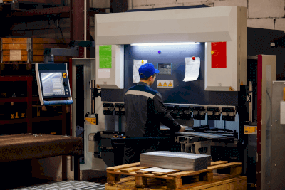
A machine press is a device that applies pressure to materials to deform and process them.

These presses use hydraulic, pneumatic, or mechanical pressure. Materials are placed between upper and lower dies, where they are shaped through shearing, bending, drawing, and other processes.

Machine presses are known for their automation capability and high productivity, efficiently processing a large volume of materials quickly and with high precision.

Uses of Machine Presses

Machine presses have various applications across industries:

1. Automotive Industry

They are crucial in manufacturing automotive parts, such as door and trunk panels, and frame parts, ensuring precision and strength.

2. Home Appliances

Used in creating metal cases and covers for appliances, machine presses facilitate the mass production of components through shearing and bending.

3. Building Materials

They produce building exterior panels and window and door fitting components, meeting durability and appearance standards.

Principle of Machine Presses

The machine presses work by applying pressure to materials, typically metal plates or sheets. The process involves using a die and a press ram, which moves up and down, to shape the material.

Material setup begins by positioning it over the die on the press base. The press head then descends, applying controlled pressure to shape the material.

Types of Machine Presses

Machine presses are categorized into mechanical and hydraulic presses, with further classification into PRG and TDM types.

1. Mechanical Press

Mechanical presses use a motor to move the slide, suitable for mass production due to their high processing speed and safety.

2. Hydraulic Press

These presses operate using hydraulic pressure, offering versatility in processing speed and pressure, ideal for parts requiring high machining accuracy.

3. PRG Method

The PRG method involves programmed control for precise shape processing, allowing complex shapes and multiple processes on the same press.

4. TDM Method

The TDM method, suitable for mass production, involves single-process operations across multiple presses, optimizing efficiency and productivity.

Other Information on Machine Presses

Production Speed of Machine Presses

Key factors influencing processing speed include the press’s stroke length, feed speed to the next process, material stability, scrap ejection, and the speed of product discharge.
カテゴリー
category_usa

Bearing Units

What Is a Bearing Unit?

Bearing Units

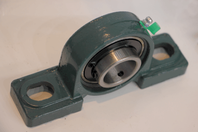
Bearing units are bearings consisting of a bearing housing and deep groove ball bearings. The term “ball bearing unit” is also used synonymously.

Bearing units have ball bearings preinstalled in the housing. Housings are available in several shapes, such as pillow-top, square flange, and rhombus flange shapes, and it is important to select the most suitable shape according to the mounting location and conditions.

Since the mounting holes in the housing allow for easy installation in equipment and facilities with bolts, etc., they are used in many machines such as conveyors and rollers that perform various rotational motions. In particular, specifications and dimensions of bearing units are standardized, making it possible to design around bearings in a versatile and standardized manner.

Applications of Bearing Units

Figure 1. How to fix the shaft

Figure 1. How to fix the shaft

Bearing units are mainly used to support shaft rotation and radial loads.

There are various types of bearing units, and the most appropriate selection must be made according to the mounting location, surrounding structure, and installation environment. This includes considerations for shape, mounting method, shaft fixing method, protective structure (with or without a cover, seal, etc.), and material.

Principles of Bearing Units

Figure 2. Structure of bearing unit

Figure 2. Structure of bearing unit

Bearing units, like other bearings, are available in radial bearing and thrust bearing types.

The load applied to the bearing is radial load, which is applied in a radial direction perpendicular to the rotating shaft axis center, and thrust load, which is applied in an axial direction parallel to the rotating shaft axis center.

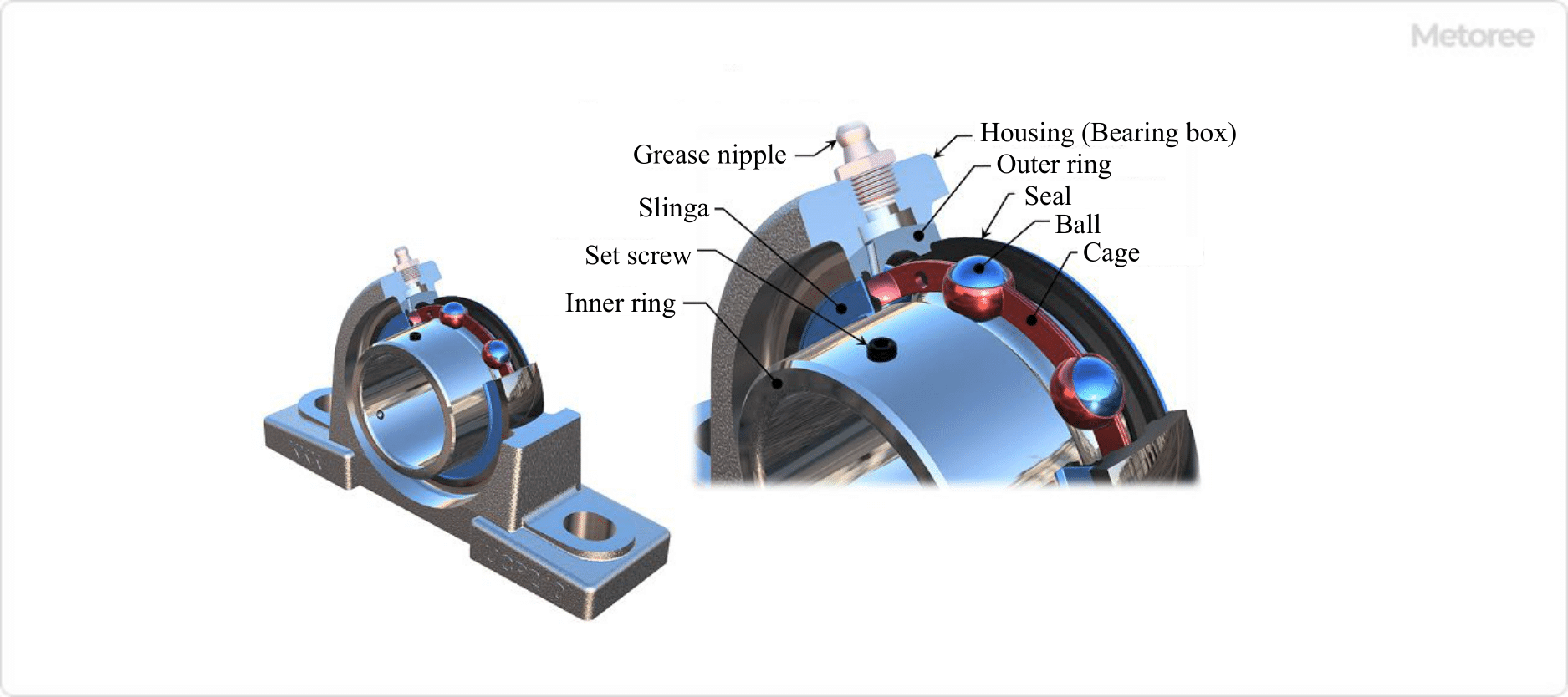
Radial bearings are used when radial loads are applied, and thrust bearings are used when axial loads are applied. The basic structure consists of a bearing housing, rolling element balls, outer ring, and inner ring. The rolling element ball is sandwiched between the outer ring and inner ring of the raceway and rotates within the raceway. A cage (retainer) maintains the distance between the rolling element balls.

Friction occurs as the balls slide and rotate between the raceways. Lubrication is necessary to reduce this friction. There are two types of lubrication methods: one in which lubricant grease is pre-filled, and the other in which grease is supplied from a grease nipple attached to the housing through a hole in the outer ring.

Types of Bearing Units

Figure 3. Types of bearing unit (1)

Figure 3. Types of bearing unit (1)

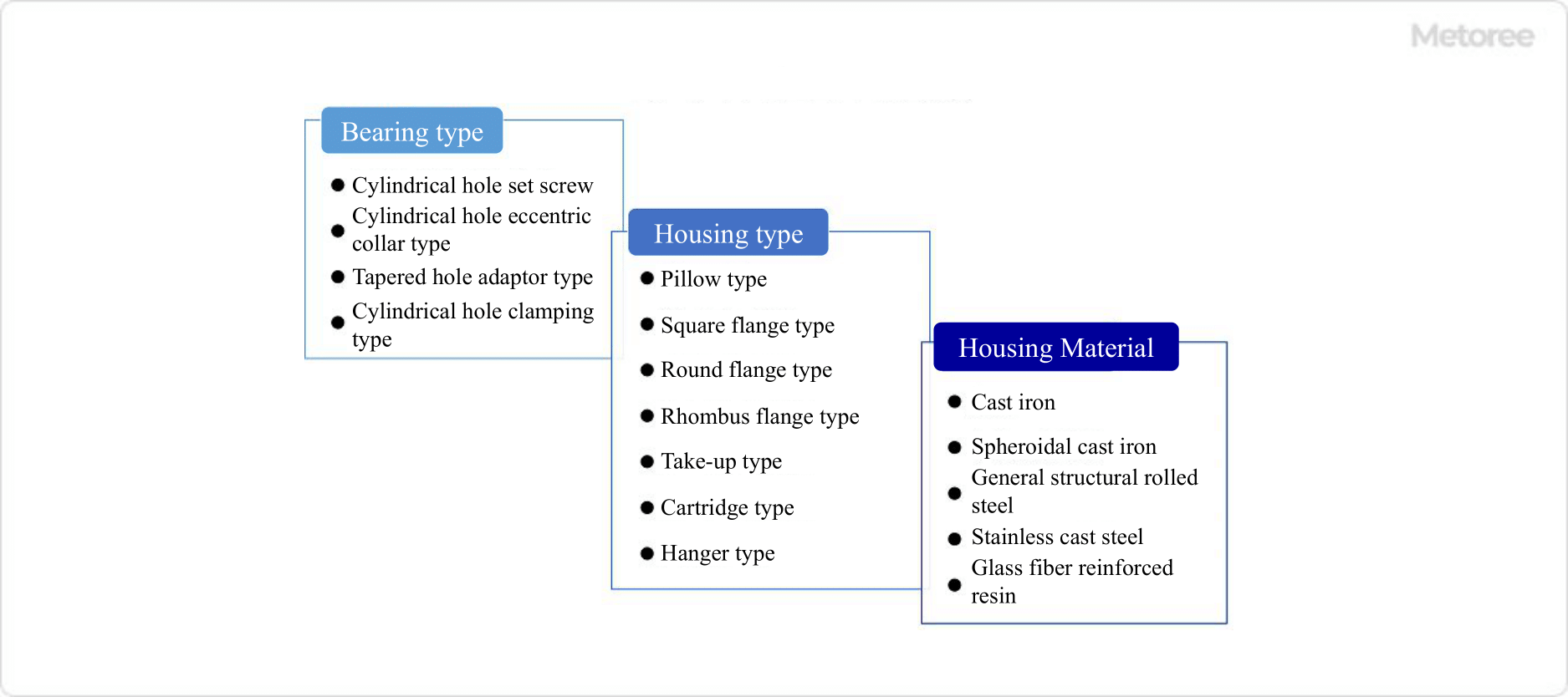
Bearing units can be classified in terms of Bearing Type, Housing Type, and Housing Material. Since there are so many types, it is important to select the appropriate one for the application.

1. Bearing Type

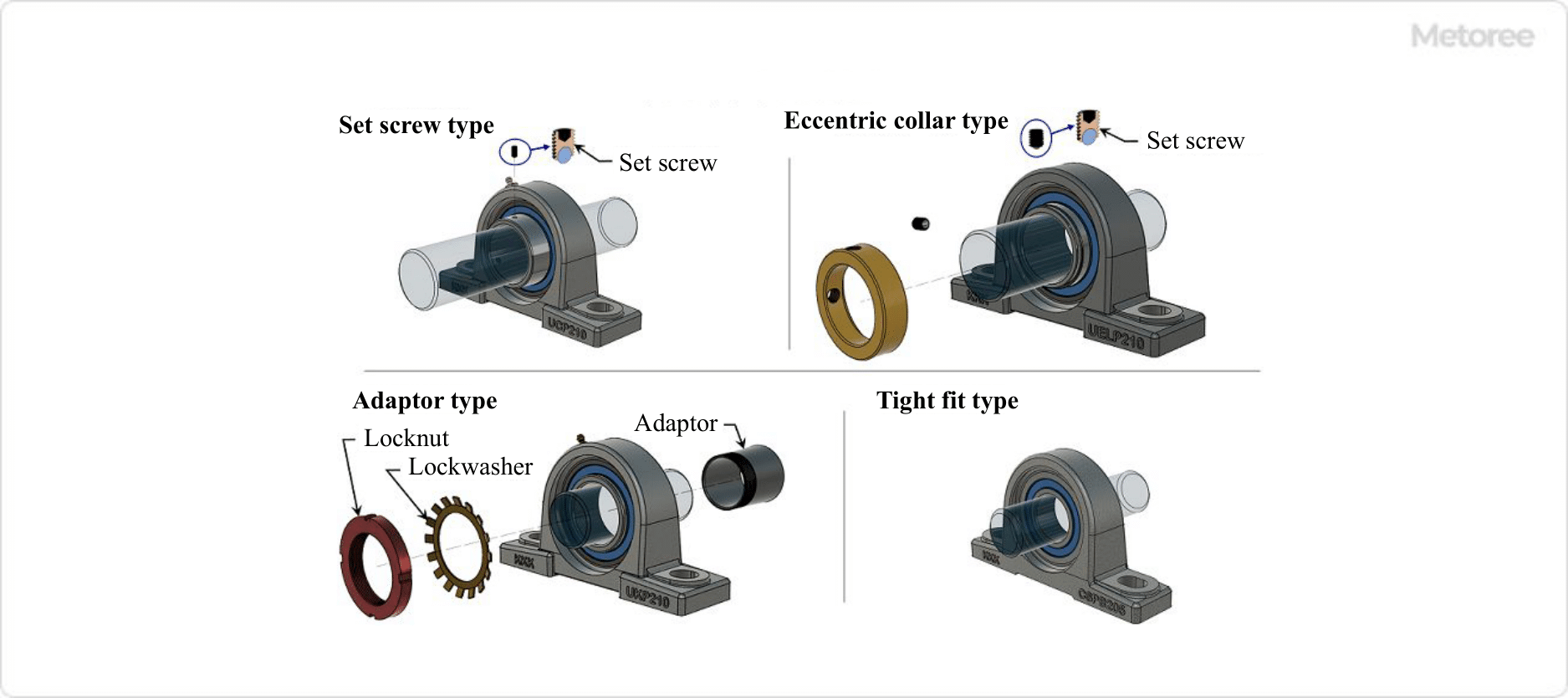
Figure 4. Types of bearing unit (2) / Figure 5. Types of bearing unit (3)

Figure 4. Types of bearing unit (2) / Figure 5. Types of bearing unit (3)

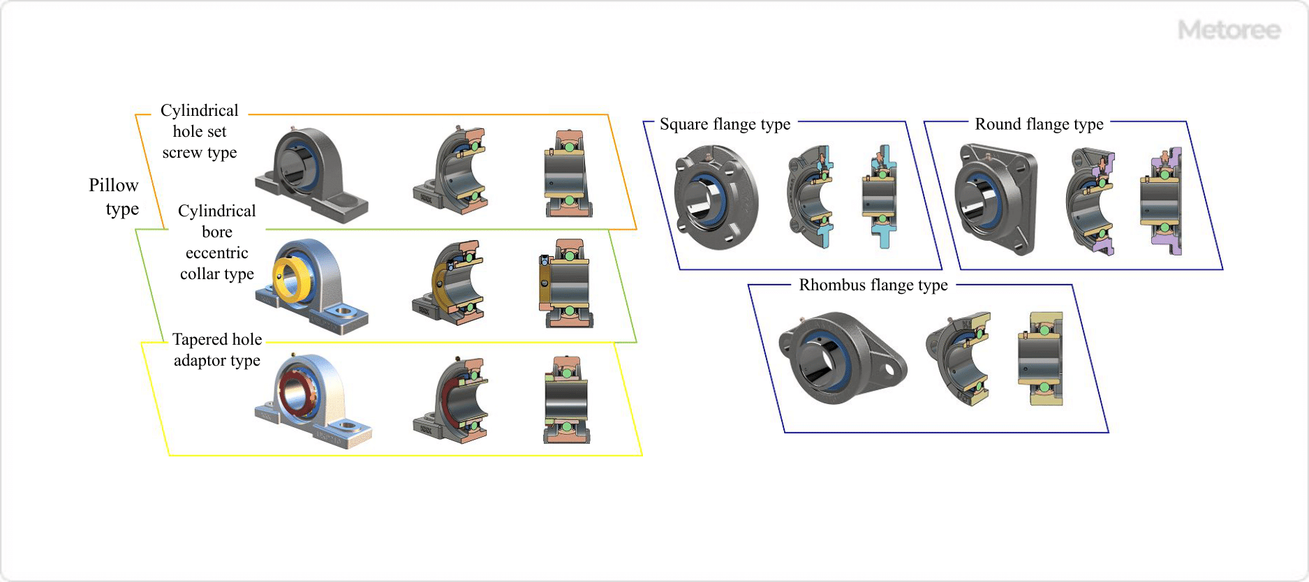
  • Cylindrical Bore Set Screw Type
    The inner ring has a cylindrical bore, and the shaft is installed inside. The inner ring set screw is then tightened to fix the bearing to the shaft.
  • Cylindrical Bore Eccentric Collar Type
    The inner ring has a cylindrical bore, and the shaft is installed in the inner ring. An eccentric collar is attached to one side of the inner ring and tightened with a set screw to secure the bearing to the shaft.
  • Tapered Hole Adapter Type
    The inner ring has a tapered bore, and a special adapter is installed between the shaft and inner ring and tightened with a bearing nut to secure the bearing and shaft. A dedicated lock washer is used to prevent the lock nut from loosening.
    A tapered bore is a conical tapered bore.
  • Cylindrical Hole Type Clamping Type
    The inner ring has a cylindrical bore, and the bearing and shaft are secured by making the fit between the shaft’s outer diameter and inner ring’s inner diameter a clamping fit.
    The tight fit is defined as a fit where there is no gap between the shaft and the bore, and the minimum allowable shaft dimension is larger than the maximum allowable bore dimension.

2. Housing Type

Figure 6. Types of bearing unit (4)

Figure 6. Types of bearing unit (4)

  • Pillow Type
    The pillow type housing is the most common housing type and consists of a cylindrical section that holds the bearings and a base section with holes drilled for bolts to secure the Bearing Units. It is used in many applications such as power transmission mechanisms and general machinery.
  • Square Flange Type
    The square flange type has a square housing flange shape and is mounted on the wall of equipment or facilities with four bolts.
  • Round Flange Type
    The round flange type has a housing with a round flange and is attached to the wall of the equipment or facility with four bolts.
  • Rhombic Flange Type
    The rhombic flange type has a rhombus-shaped housing flange and is attached to the wall surface of the equipment or facility with two bolts. It is relatively small in external dimensions and can be installed in a small space.
  • Take-Up Type
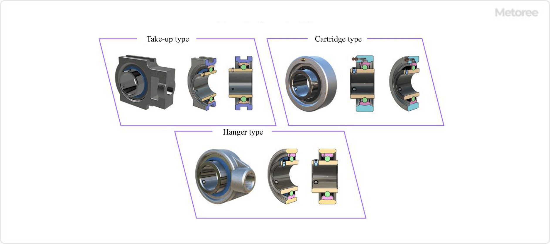
    The take-up type has a sliding groove on the left and right sides of the housing. This groove fits into a guide on the equipment, etc., and the entire Bearing Units move left to right or up and down, and the shaft position needs to be moved.
  • Cartridge Type
    The cartridge type has a simple cylindrical housing without a base or flange shape. The housing and outer ring are spherical and aligned. Cartridge type is used to absorb the expansion and contraction of the shaft, such as moving it in the axial direction. Used on the free side (moving side) of expansion and contraction.
  • Hanger Type
    The hanger type has a threaded hole on one side of the housing and is used to support the shaft by screwing in a suspension shaft or the like.

3. Housing Material

  • Cast Iron
    The housing material used is gray cast iron. This is the most common and standard housing material.
  • Spheroidal Graphite Cast Iron
    The housing material used is spheroidal graphite cast iron. It is applied when higher mechanical strength than cast iron housing is required.
  • Rolled Steel for General Structural Purposes
    The housing material used is rolled steel for general structural purposes.
  • Cast Stainless Steel
    Stainless steel casting is used for the housing material. Applicable to outdoor use environments or when splashed with water, or where nitric acid or sulfuric acid corrosion resistance is required. Martensitic stainless steel is used for the ball, inner ring, and outer ring.
  • Glass Fiber Reinforced Resin
    Thermoplastic polyester resin, polypropylene, and polyethylene are used as housing materials. They can be used in environments subjected to water or seawater or underwater, and are applicable to environments where sulfuric acid or hydrochloric acid corrosion resistance is required.
カテゴリー
category_usa

Peltier Modules

What Is a Peltier Module?

Peltier Modules

A Peltier module is a device that utilizes the thermoelectric effect to interchange heat and electricity.

It transfers heat in one direction using the Peltier effect, discovered by French physicist Jean-Charles Assayul Peltier in the 19th century. This effect occurs when electrical current flows between different types of conductors, causing heat transfer. Peltier modules typically consist of numerous elements made from ceramic or semiconductor materials.

Due to their compact size and efficient control performance, Peltier modules are widely used in the cooling and thermal management of electronic devices. They operate without mechanical parts, thus reducing noise and eliminating wear and tear. However, they have limitations in efficiency and are sometimes less effective than other cooling and heating technologies.

Uses of Peltier Modules

Peltier modules have a range of applications:

1. Cooling of Electronic Equipment

These modules are instrumental in dissipating heat from electronic equipment, such as CPUs and graphics cards in computers. They attach directly to these components, reducing their operating temperature and enhancing performance stability and reliability.

2. Refrigerators and Cooling Devices

Peltier modules are also found in some compact refrigerators and cooling units, valued for their small size, quiet operation, and portability. They are common in personal-use coolers and hotel room refrigerators. For larger capacity or higher efficiency cooling, other types of chillers are often more suitable.

3. Cooling of Optical Equipment

In optical devices such as telescopes and lenses, Peltier modules help maintain stable optical characteristics by minimizing temperature-induced changes. They are also used to prevent overheating in semiconductor lasers and similar devices.

Principle of Peltier Modules

Peltier Modules operate based on the thermoelectric effect. This phenomenon involves heat transfer when electrical current flows through different types of conductors. The module consists of P-type and N-type semiconductors and metal, bonded between two metal plates. The flow of current from N-type to P-type semiconductors causes one junction to cool and the other to heat.

The Seebeck effect, or reverse Peltier phenomenon, occurs when a temperature difference is applied to a Peltier module, generating voltage. This principle is utilized in thermocouple thermometers.

How to Select a Peltier Module

Consider these factors when selecting a Peltier module:

1. Operating Voltage

Choose a module with an operating voltage compatible with your power supply and control system. Most low-voltage Peltier modules operate at 30 V or lower.

2. Generated Temperature Difference and Heat Absorption

Select a module based on the required cooling or heating capacity, considering its temperature difference generation and heat absorption capabilities.

3. Dimensions and Shape

Consider the intended environment and equipment constraints. Modules should fit the space and shape of the installation site. If specific dimensions or shapes are required, choose accordingly.

カテゴリー
category_usa

Drill Presses

What Is a Drill Press?

Drill Presses

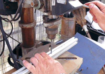
A drill press is a machine tool used to drill holes in materials such as wood, resin, and metal.

The material is fixed to the table, and a cutting tool such as a drill or reamer attached to the main spindle is rotated and the spindle is lowered toward the material for drilling. Drill presses are capable of drilling, expanding, reaming, tapping, buckling, and boring.

Uses of Drill Presses

Drill presses are often used to process and modify prototype parts before mass production.

Drill presses are not suitable for mass production, as milling machines and machining centers are superior in terms of automation. They are less expensive than other machine tools and are used for DIY and other personal manufacturing projects.

Drill Presses Principle

Drill presses can be used for a variety of machining operations by changing the tools to which they are attached.

1. Drilling

The basic use of a drill press is to drill a hole in a workpiece using a drill. This process includes ordinary solid drilling and trepanning, in which a large-diameter hole is drilled leaving a cylinder in the center of the hole. 

2. Boring

A cutting tool called a boring bit is used to widen the inside diameter of the drilled hole to achieve dimensional accuracy.

3. Spot Boring

A large-diameter step is drilled into the top of the drilled hole using a boring drill, which is often used for hexagonal bolts.

4. Reaming

A tool called a reamer is used to improve the accuracy of the drilled hole. It is important to increase the rigidity of the spindle and chuck, since any vibration of the spindle or chuck will deteriorate the machining accuracy.

5. Threading

Threading is the process of creating the threads of a female thread using a tool called a tap in a drilled hole.

Types of Drill Presses

Drill presses come in a variety of types.

1. Upright Drill Presses

The most common drill presses are floor-mounted. The spindle head is moved manually or mechanically in the vertical direction to drill holes in workpieces placed directly under the spindle. The rotation speed of the main shaft can be changed by replacing the reduction gear. The hole diameter is about 13-50 mm.

2. Radial Drill Presses

Drill presses are larger than upright drill presses. The spindle head is mounted on a movable arm, and by moving the arm, several holes can be drilled without moving the large workpiece.

3. Tabletop Drill Presses

This is the smallest drill presses and is mainly used for DIY and simple processing. Drill presses are less accurate than upright drill presses, but they are easier to use. Hole diameter is up to about 13 mm.

4. Turret Ball Machine

A swivel table with several types of tools mounted on the main spindle allows multiple work processes by sequentially changing tools.

5. NC Drill Presses

High-precision machining is performed automatically by numerical control.

6. Other Drill Presses

Multi-axis drill presses are drilling presses with an increased number of spindles and can process multiple holes at the same time. Some drilling machines have 50 spindles and are used for machining special parts, etc., rather than general-purpose machines. A multi-head drilling machine is equipped with a large number of spindle heads, and can perform processing such as drilling, counterboring, and tapping in sequence with a single machine.

Other Information on Drill Presses

How to Use Drill Presses

1. Securely Install the Drill

If the drill is not securely fastened to the chuck, it will run dry during machining, resulting in loss of machining accuracy and damage to the Drill Presses.

2. Safety First

The use of gloves is extremely dangerous as they can get caught in the drill.

3. Fixation of Workpiece

The workpiece must be securely fastened using a clamp or vise.

4. Appropriate Rotation Speed

Appropriate rotation speed and feed rate should be selected according to the diameter of the drill and the hardness of the workpiece.

カテゴリー
category_usa

Linear Scales

What Is a Linear Scale?

A linear scale, also known as a linear encoder, measures position or distance along a straight line with high precision, outputting this information as an electrical signal. These devices come in two main types: absolute, which calculates travel from a fixed point, and incremental, which measures distance traveled without a fixed reference point.

Linear scales employ either electromagnetic detection, based on electromagnetic induction, or optical detection, which involves reading light passed through a coded pattern. Electromagnetic versions are more common due to their broader application range.

Uses of Linear Scales

Linear scales are integral in machine tools and semiconductor manufacturing for precise movement control and measurement. Electromagnetic types, favored for their simplicity, are widely used in versatile tools like digital calipers, essential in numerous manufacturing settings for measuring distances between two points.

Principle of Linear Scales

The electromagnetic linear scale operates on electromagnetic induction, generating an electromotive force that correlates with distance variations between its main scale and detector coil. This indirect measurement translates movement into distance data. Although simple and robust, these scales are not suitable for environments with strong magnetic fields.

Optical linear scales, on the other hand, function by emitting light across a main scale and reticle grating, creating interference fringes that are converted into electrical signals for precise positioning. These scales offer higher accuracy and are unaffected by magnetic fields but are more sensitive to external light and typically larger.

Other Information on Linear Scales

1. How to Use Linear Scales

Employed in semiconductor production and machine tooling, linear scales are crucial for detecting and controlling exact positions. They are often used in conjunction with laser interferometers and encoders for enhanced precision. The rapid advancement in semiconductors, propelled by Moore’s Law, demands increasingly accurate position detection in manufacturing, making linear scales indispensable for the precision fabrication of electronic devices and mechanical parts.

2. Installation of Linear Scales

Given their pivotal role in precision equipment, linear scales must be mounted with utmost accuracy to maintain their high precision, sometimes requiring resolutions of a micron or less. Proper installation, as detailed in manufacturers’ manuals, is crucial to a linear scale’s performance, often necessitating custom jigs or manual adjustments during setup to achieve the necessary alignment and precision.

カテゴリー
category_usa

Level Gauges

What Is a Level Gauge?

Level Gauges

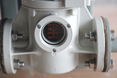
A level gauge is an instrument used to measure the level of liquid or powder within a container. These devices are crucial for monitoring levels to prevent leaks, overfilling, and ensuring efficient material usage. They vary in design and principle, and selecting the appropriate type for specific applications is essential.

Uses of Level Gauges

Level gauges find application in various sectors:

  • In the industrial sector, they are used for monitoring liquids in tanks where direct visual inspection isn’t feasible.
  • In boiler systems, accurate level control is critical for safety and operational efficiency.
  • For liquid fuel tanks, they aid in fuel management and supply control.
  • In automotive applications, they are used for checking engine oil levels.

Principle of Level Gauges

Level gauges operate on various principles, with the glass gauge type utilizing Pascal’s principle. This principle states that fluid pressure in a closed system is proportional to the liquid level. In tanks, the fluid level in the gauge will equalize with the tank level, allowing for indirect level monitoring.

Types of Level Gauges

Common types of level gauges include:

  • Glass Gauge Type: Uses a transparent glass tube to visually indicate the liquid level. It is simple and reliable but may not be suitable for harsh conditions.
  • Float Type: Measures levels using a float that responds to liquid level changes. This type is versatile and can be used in various conditions, including high temperatures and pressures, but may not be ideal for sticky fluids.
カテゴリー
category_usa

Rolling Mills

What Is a Rolling Mill?

Rolling Mills

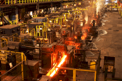
Rolling mills are used in steel mills to stretch steel.

Rolling is the process of stretching steel. The final thickness of the steel produced in a mill determines the number of rolling mills. Rolling mill stretches the steel by crushing it between motor-driven rolls, controlling the thickness (width) to a target value, which varies from product to product.

During rolling, it is important to stretch the iron that has been heated in the furnace before lowering the temperature.

Uses of Rolling Mills

Rolling mills are used to stretch steel. The main flow of rolling mills varies from mill to mill, but generally there are one to five roughing mills that roughly stretch the thick steel coming out of the furnace, followed by five to eight finishing mills that finish the steel to the actual thickness of the product.

Rolling mills can be broadly classified into roughing mills and finishing mills. Some roughing mills are equipped with a function called reverse rolling, in which the rolled steel is returned to the front of the rolling mill and rolled again in the same rolling mill. This method allows thick steel to be rolled to a certain degree of thinness.

Principle of Rolling Mills

The rolling mill stretches the steel between two rolls, which must be pressed down in order to stretch the steel. The pressing function is called “pressing down” and is driven electrically or hydraulically.

In order to control the thickness at the exit of each rolling mill, a position sensor or other device is attached to the screw or other parts of the roller if it is electrically driven. By linearly detecting the position, the amount of pressure drop is calculated to determine the material thickness.

In the case of hydraulic pressing, the material thickness is calculated by linearly monitoring the position of the cylinder inside the pressing equipment. Mainly, roughing mills often use only electric pressure reduction, while finishing rolling mills often use a combined electric and hydraulic pressure reduction system.

In finishing mills, the control method called automatic gap control (AGC) is also used, which is based on thickness feedback in combination with thickness gauges, such as X-rays and γ-rays, to eliminate errors from the target thickness. Therefore, AGC control is performed in combination with these factors as well.

Types of Rolling Mills

The following are the main types of rolling mills used in the rolling process. 

1. 2-High Rolling Mill

Two-High Rolling Mill is the simplest type of rolling mill, with two rolls (working rolls) on the top and bottom, and is used for rough rolling of 20mm to 30mm and thin sheet rolling.

2. 4-High Rolling Mill

A 4-high rolling mill consists of two additional rolls (support rolls) added to the working rolls of a 2-high rolling mill. 4-high rolling mills do not use four rolls to roll metal, but rather sandwich the working rolls between the support rolls. The support rolls hold the deflection of the working rolls, enabling highly accurate processing. 

3.Multi-Stage Rolling Mill

A multi-stage rolling mill is a rolling mill with more working rolls than a 4-stage rolling mill. Multi-stage rolling mills come in a variety of shapes and sizes, and each has many working rolls, enabling the processing of hard metals under high pressure. In addition, the shaft diameter of the rolls can be reduced for processing, making it possible to roll extremely thin materials such as silver foil.

Other Information on Rolling Mill

Types of Rolling Processes

Rolling mills are classified into three types: hot rolling, cold rolling, and warm rolling, depending on the temperature at which the rolling process is performed.

1. Hot Rolling 
Hot rolling is a rolling process in which the metal is heated to 900°C to 1,200°C to soften it for easier processing. The metal is then passed through rolls and rolled.

The high temperatures result in a material with good workability and tenacity. However, the surface becomes whitish due to oxidation.

2. Cold Rolling 
Cold rolling is a method of rolling at room temperature. The temperature is not heated as in hot rolling, but the heat generated in the metal rolling process raises the temperature somewhat.

The dimensional accuracy is higher than that of hot rolling, and the surface is shiny. 

3. Warm Rolling P
The warm rolling process is an intermediate rolling method between hot rolling and cold rolling. It produces a finish that compensates for the disadvantages of hot rolling and cold rolling. It is often used in the production of aluminum foil.

カテゴリー
category_usa

Instrument Washers

What Is an Instrument Washer?

An instrument washer is a machine that automatically cleans a laboratory equipment used in experiments and manufacturing.

In research and development, dirty laboratory equipment can affect the results of experiments, while cleaning the equipment is time-consuming. Instrument washers are therefore used to improve operational efficiency.

In addition, in the food industry and biotechnology industry, it is necessary to carefully sterilize the instruments and equipment used, and the instrument washer is also used at that time.

Instrument Washers Use Steam, Jets of Water, and Detergent to Remove Contaminants.

Instrument washers are equipped with nozzles and spray water to remove stains, while others use hot steam to remove stains. Detergent for cleaning utensils may also be used.

Uses of Instrument Washers

Instrument Washers Are Used in R&D and the Food Industry.

Instrument washers are used to clean equipment in R&D and manufacturing.

In R&D, the type of contamination varies depending on the industry and the reagents used, so the detergent used in instrument washers is changed accordingly.

In the food industry, instrument washers are used to clean the equipment used in manufacturing.

Instrument washers used in the food industry can also use sterilized water and are also used to sterilize instruments.

Instrument washers are also available for cleaning and sterilizing microchips and other instruments frequently used in bio-related experiments.

Features of Instrument Washers

Instrument Washers clean by rotating the nozzles and racks inside.

Instrument washers are equipped with racks and nozzles. Appropriate racks are selected according to the shape and size of the instruments to be cleaned. As an option, racks dedicated to instruments frequently used in experiments, such as test tubes, are also available.

Equipment washing is performed by spraying water from the nozzle. Water can be sprayed all over by rotating the nozzle or rack. In addition, depending on the model number of the device, it is also possible to fill the inside with high-temperature steam for sterilization.

Wear Protective Gloves When Using Detergents in Instrument Washers; There Are Various Types of Detergents Used in Instrument Washers.

Strong alkaline and acidic detergents can be used to remove adhered organic contaminants.

It is recommended that protective gloves be worn when handling detergents to prevent chemical injury. In the unlikely event that detergent gets into the eyes, the eyes should be rinsed immediately with plenty of running water.

If powdered detergent is used with instrument washers, there is a possibility that the detergent may remain on the instruments.

カテゴリー
category_usa

Electrostatic Actuators

What Is an Electrostatic Actuator?

An electrostatic actuator is a device that moves object by converting energy generated by electrostatic forces into motive force.

Actuators are mainly used in the field of optics, including components such as variable focus lenses, shutters, and displays.

Characteristics include light weight, flexibility, thinness, and transparency.

Examples of research include artificial muscles, hands, and legs for robots, with ongoing development to enable movements similar to actual human parts.

Applications of Electrostatic Actuators

  • MEMS (Micro Electro-Mechanical Systems): Often used to drive MEMS, which are a general term for semiconductors and electronic circuits with moving parts. Unlike ordinary semiconductors, MEMS require small parts, necessitating thin electrostatic actuators.
  • Artificial Muscles: Devices supporting human movement, such as care robots, artificial legs, and hands, require these actuators for flexible and complex movements.

Principles of Electrostatic Actuators

These actuators operate based on parallel plate capacitors. The electrostatic force generated is proportional to the plate area and inversely proportional to the square of the distance between the plates. Their small size leads to a lower absolute driving force, which is often compensated by increasing the area of the actuators or using thin films.

In addition to electrostatic types, other actuators include:

  • Thermal Actuators: Easy to manufacture but vary in driving force due to material anisotropy.
  • Electromagnetic Actuators: Usable in liquid, broadening application range.
  • Piezoelectric Actuators: High driving force, with a downside of hysteresis loss reducing effectiveness.
カテゴリー
category_usa

Dielectric Strength Testers

What Is a Dielectric Strength Tester?

A dielectric strength tester is an instrument for assessing the dielectric strength of electrical equipment and electronic components. It confirms that these items are adequately insulated, safeguarding against hazards like leakage and short circuits. Insufficient insulation heightens the risk of electric shock and fire. These testers are crucial for conducting dielectric tests by applying specific voltages to meet regulatory compliance and ensure product quality.

Uses of Dielectric Strength Testers

Dielectric strength testers are essential in manufacturing and ensuring the safety of various electrical equipment and electronic components, with applications including:

1. Electrical Construction

They are vital for high-voltage equipment testing, such as cables and transformers, to ensure safety, proper functioning, and quality of construction work by identifying equipment damage and insulation failures.

2. Electrical Product Manufacturing

In the production of electrical devices like computers and televisions, these testers evaluate insulation effectiveness and detect flaws, preventing the circulation of defective products.

3. Research and Development

They play a role in developing new electronic devices and components, testing and enhancing insulation of novel materials and designs, and verifying that new products meet dielectric strength requirements.

Principle of Dielectric Strength Testers

The principle involves applying a voltage to measure insulation resistance, thus evaluating an item’s insulation. The process involves applying a sinusoidal AC voltage, from hundreds to several kilovolts, to test the material’s capacity to withstand high voltages and measure insulation resistance by detecting leakage current, with higher resistance indicating better insulation.

How to Select Dielectric Strength Testers

When choosing a dielectric strength tester, consider factors such as:

1. Applied Voltage

Select a tester that offers a voltage range suitable for the intended application, especially for high-voltage tests.

2. Power Supply

Ensure the tester’s power supply compatibility with the site’s power source, considering AC, DC, and battery-powered models for mobility.

3. Leakage Current Range

The tester should have a leakage current measurement range that aligns with the test subject’s specifications, particularly for low leakage current requirements.

4. Auxiliary Functions

Consider testers with features that enhance usability, such as user-friendly interfaces, data management capabilities, and automated testing processes.