カテゴリー
category_usa

Flux

What Is Flux?

Flux

Flux is a soldering agent made mainly from resin.

Flux is an organic substance found in trees, most famously pine resin, which is a sticky liquid. The flux is made by mixing the resin with an activator.

When electronic components are mounted on a circuit board, a soldering iron is used to melt a long, thin piece of metal called solder to form a joint.

Flux is mixed with this solder.

If the flux is not used, not only will the product not be completed, but it will also result in a large number of defective products, which could lead to an accident.

Uses of Flux

The main use of flux is for bonding electronic components.

If you look at an electronic circuit board, you will see many rounded pieces of silver metal. This metal is solidified from the solder that has been melted by heat, and flux is added to the solder to keep it from oxidizing and forming.

There are also fluxes for joining metals, which are mixed with solder when metals are soldered together.

There is also flux for stainless steel. Stainless steel forms a passive film on its surface. A flux is used to remove this passive film.

Characteristics of Flux

The number one feature of flux is that it allows the solder to form on the electronic board without degrading its quality.

When solder is melted, the work area is often at room temperature, and the melted solder is highly heated. This causes the metal surface of the melted solder to oxidize, resulting in defective electronic substrates.

The role of flux is to inhibit the oxidation of solder, and a film of flux is formed to cover the metal surface.

In addition, the solder itself has high surface tension and quickly becomes spherical when melted in the normal way. To prevent this from happening, flux is added to lower the surface tension of the solder.

On the other hand, the disadvantage of flux is that it remains attached to the solidified metal and remains on the electronic board.

Since flux is intended to condition the basic solder, it is unnecessary once the solder has solidified successfully.

However, if flux remains, the PCB will be defective, and the PCB will need to purchase a special cleaning agent to remove it, or consider the use of a large cleaning machine.

カテゴリー
category_usa

Flat Cable

What Is a Flat Cable?

Flat Cables

A flat cable is a type of cable used for inter-device wiring, consisting of multiple core wires bundled in parallel to form a flat cable.

Each core wire is made of thin conductors coated with resin insulation, and the number of cables varies from about 10 to 100. A flat cable that is relatively narrow in width is sometimes called a ribbon cable.

Since flat cables can send multiple signals at once, they are used to connect devices with parallel interface functions.

Uses of Flat Cables

Flat cables are suitable for parallel interfaces that send multiple signals at the same time. They are used as wiring cables between devices with parallel interface functions, such as computers, peripheral devices, communication devices, and office equipment.

Flat cables are flat, soft, and can be bent for wiring. However, they have the disadvantage of being weak and may cause noise interference. For this reason, they are used for internal wiring of electronic devices such as hard disks, drivers, and boards inside PCs, rather than for wiring to and from external devices.

Characteristics of Flat Cables

There are various types of flat cables, such as bridged, threaded, and twisted pair cables.

The bridge type flat cables are the most common type of flat cables, with each core wire completely fused together.

Sudare flat cables have a structure in which the fusion-bonded and non-fusion-bonded portions of each core wire alternate at regular intervals. The non-fused portions are usually longer and allow for more flexible wiring than the bridge type, making it suitable for wiring in enclosures with complex shapes.

Twisted-pair flat cables have a twisted-pair structure, in which the non-fused portions of the Sudare type are twisted into pairs of two cores each. Compared with the bridge type and the wire of the Sudare type, the twisted pair of flat cables is more resistant to crosstalk and noise from neighboring cores.

There is also a type of cable that is rounded from the Sudare type flat cables and covered with a shield, which is called a round cable. Since round cables are stronger and more resistant to noise than flat cables, they can be used not only for wiring within electronic equipment but also for wiring between external devices.

カテゴリー
category_usa

Flapwheel

What Is a Flapwheel?

Flapwheels

A flapwheel is used for metal polishing. It is attached to the tip of an electric drill, air drill, or router. It has a structure in which the polishing cloth is fixed in a radial position. As with sandpaper, the coarseness of the grit is determined by the number of grit, and the larger the number, the finer the grit.

There are also various types, from large to small, according to the size of the part to be polished. Furthermore, since the product has a self-controlling effect, and can be used for a relatively long time.

Uses of Flapwheels

Flapwheels are often used for machine maintenance tasks. They are very efficient in removing rust and polishing quickly, whereas polishing by hand would take too much time. They are also used for rough polishing before final polishing during product production. For final polishing, a felt fabric part called a buff is used. It can be used in conjunction with abrasives to achieve a fairly shiny finish.

Also, due to its structure, flapwheels have an air-cooling effect and are less likely to give off heat to the object to be polished. Therefore, strain and burning can be eliminated.

Features of Flapwheels

Flapwheels are used for various processes, including deburring and removing scratches on machine parts. Their structure does not cause clogging during polishing, thus enabling uniform finishing surfaces. This is due to their self-sharpening action, as mentioned above. Also, because of its cylindrical shape, it can be used for parts with curved surfaces (pipes and spheres). When polishing cylindrical-shaped parts, even if the inside diameter is smaller than the hand, a smaller diameter flapwheel can be used.

Flapwheels can be used to clean up burn marks after welding. The use of flapwheels allows for a clean surface finish without leaving burn marks.

However, the flapwheel must be kept parallel to the material in order to achieve a clean, polished surface. If the flapwheel is applied at an angle, the surface will not be even, and the flapwheel itself will be unevenly worn instead of a clean cylindrical shape.

Flap foils can also be used for polishing wood as well as metal materials. The same advantages apply to wood as to metal.

カテゴリー
category_usa

Flange

What Is a Flange?

Flanges

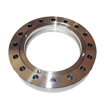
A flange is a flat “brim-shaped” plate attached to a pipe, duct, device, or other equipment. A flange is used to connect pipes, equipment to pipes, and shafts to each other or shafts to rotating machines.

When machines or parts are fastened and joined with bolts, nuts, etc., the flat surface of a circular or rectangular-shaped joint is sometimes called a flange. A flange allows for a highly accurate and sealed joint. The brim of the wheel of a railroad car, or the part where a tire wheel is attached to the axle side of an automobile, is also called a flange.

Uses of Flanges

Compared to other pipe fittings, flanges can be used repeatedly and provide a high degree of sealing. Due to their ease of disassembly and reassembly, flanges are often used to connect pipes used in ships, railroads, and factories. In particular, flanges are used to join pipes in many cases where the fluid flowing in the pipes is used under special conditions, such as high temperature, low temperature, high pressure, or vacuum.

Flanges are used to join pipes together by inserting a gasket (sealing material) between two flanges and tightening them with bolts and nuts.

Assembled gaskets come in various types and shapes, and the appropriate gasket must be selected according to the temperature and pressure of the fluid to be used. The following are examples of gasket types:

Joint Sheet Gasket: A gasket made of carbon fiber or other material filled with rubber and formed into a flat sheet, which is cut and used according to the seating dimension of the flanges.

Spiral-wound Gasket: A gasket consisting of a metal hoop with a V-shaped cross-section and filler (cushioning material) overlapped and rolled into a spiral shape.

Ring Joints: Metal gaskets with oval or octagonal cross sections and made of mild steel, stainless steel, Monel, or other materials. It is mainly used in the petroleum industry.

Characteristics of Flanges

This section describes the steel pipe type of flanges used to connect pipes.

Flanges are mainly classified by shape, fluid pressure used, pipe connection method, gasket type, and other factors, from which the appropriate type of flanges with the appropriate specifications is selected.

The following are examples of flange types:

Slip-Welded Flange (SOH)

A slip-welded flange, also called a slip-on flange, is attached and secured by inserting a pipe into the flange hole and performing a fillet weld between the top of the flanges and the outer surface of the pipe, and between the bottom of the flange hole and the outer surface of the pipe. This is the most commonly used flange.

Socket-Welded Flange (SW)

Socket-weld flanges are installed by inserting a pipe into the flanges hole up to the back step and then veneer-welding the top surface of the flanges and the outer surface of the pipe to secure the flanges in place. If the temperature of the fluid to be used is high, a larger gap is often welded between the step in the flange hole and the end face of the pipe to accommodate the thermal expansion of the pipe. In this way, even if the pipe expands due to the heat of the fluid, it will hit the flange hole step and the reaction force will prevent damage to the weld.

Butt-Welded Flange (WN)

Butt-welded flanges, also called weld-neck flanges, are often used for larger pipe diameters (e.g., 2-1/2B or larger) due to their superior strength. Although it is difficult to fix the pipe and flanges straight and concentric and weld them together, it is a highly reliable joining method for this type of flanges.

Threaded Flange (TR)

Threaded flanges are also called threaded flanges. Although it is easy to install piping, there is a possibility of leakage from the threaded part if the pressure of the fluid to be used is high.

Loose-Joint Flange (LJ)

Loose flanges, also called wrap-joint flanges, are pipes with a stub end (stub end) that are attached to the flanges by fitting a pipe into the flange hole. The pipe can be oriented by loosening the nut on the flanges. Although the piping installation work is easy, the sealing performance is not relatively high, so the fluid used should be low pressure and low temperature.

Closed Flange (BL)

Closed flanges, also called blind flanges, are installed to prevent fluid leakage when the fluid is closed at the end of a pipe or when the flanges are temporarily unfastened.

Mounting Flange (MF)

Flanges with male and female seats are used in combination with flanges with two different seat configurations. The grooves of the flanges fit into each other, which enables accurate centering.

Groove Flange (TG)

A combination of two types of flanges with groove-shaped concave and convex seating surfaces. It is characterized by excellent sealing properties.

Gasket Seat Shape

There are two types of gasket seat shapes: Full Face (FF) and Flat Face (RF). Full face seating is used for flanges with a nominal pressure of 10K or less, etc. Flat face seating is the commonly used seating shape.

However, flange selection is not calculated and verified based on the above calculations, rather flanges with a nominal pressure (rating) are selected from the table according to the maximum working pressure and temperature of the fluid to be used.

カテゴリー
category_usa

Flexible Shaft

What Is a Flexible Shaft?

Flexible Shafts

A flexible shaft is a flexible shaft that transmits rotational motion between two distant points when the rotation shafts are not concentric (the longitudinal centers of the shafts are not the same).

The flexible shaft transmits rotation and torque from the drive shaft side to the driven shaft side while maintaining an appropriate bend between the shaft ends.

Therefore, the rotating shafts of the equipment do not need to be concentric with each other, allowing for a certain degree of freedom of arrangement. This eliminates the need for accurate centering between the rotating shafts of the equipment (aligning the center of the shafts with each other) and improves workability.

Uses of Flexible Shafts

Flexible shafts are used for power transmission and remote control.

  • For Power Transmission
    Flexible shafts are used when the driven shaft position is not concentric when transmitting power from an electric motor, etc.
  • For Remote Operation
    Used for manual operation of rotating equipment or remote operation of valve opening/closing.

Familiar examples include flexible bits and flexible screwdrivers for extensions of electric drills and screwdrivers, handles for remote opening and closing of windows in high places, and speedometers for automobiles.

Structure of Flexible Shafts

A typical flexible shaft consists of the following three parts The inner core (inner shaft), the outer flexible tube (outer tube or housing), and a fitting at the shaft end.

1. Core

The core consists of one core wire in the center and multiple steel wires wrapped around the core wire, alternating the direction of wrapping to produce several layers. SW-C JIS G3521 hard steel wire or SUS304WP-B JIS G4314 stainless steel wire for springs can be used for the core material.

The characteristics differ depending on the number of wires per layer, wire diameter, number of wire layers, spacing between wires, and material.

2. Flexible Tube

Mild steel wire and hard steel wire are combined and wound together. The outer surface of the wound flat steel wire is sometimes covered with a resin such as synthetic rubber, polyethylene, or vinyl chloride.

The gap between the core and the flexible tube is filled with grease or other lubricant, and the inner surface of the flexible tube acts as a bearing for the core to maintain smooth rotation.

3. Shaft End

This is a metal fitting that connects the drive side and the driven side. It is attached to the core by crimping (caulking), welding, or brazing.

Principle of Flexible Shafts

1. Core

The core is the backbone of a flexible shaft that maintains its bent state and transmits rotation. The winding of the outermost layer of the core determines the direction of rotation of the flexible shaft itself. When the outermost layer is left-handed (leftward), it is for right-handed rotation (clockwise CW), and when the outermost layer is right-handed (rightward), it is for left-handed rotation (counterclockwise CCW).

2. Flexible Tube

Flexible tubing protects the core from dust and moisture. It externally supports the core as it rotates to keep it free from torsion.

3. Shaft End

This part is used to connect the flexible shaft to the rotating shaft. It should be selected according to the connection method and shape of the other side to be connected.

Types of Flexible Shafts 

Flexible tube types include standard type, high-torque type, dual-use type, hardened type, strong type, and flexible type.

1. Standard Type

Steel wire is wound into a tubular shape and the outer surface is covered with vinyl or rubber. Highly durable and strong in torque transmission.

2. High-Torque Type

Flat steel wire is wound into a spring-like tubular liner and its outer surface is reinforced with braided steel wire, and the outermost layer is covered with vinyl or rubber. It is capable of withstanding high torque. 

3. Dual-Use (Left-Right) Type

Used as an extension of a screwdriver and structurally resistant to reverse rotation.

4. Quenching Type

Heated in a continuous quenching furnace and manufactured through quenching oil. It has excellent straightness and is suitable for remote control.

5. Strong Type

Highly resistant to impact and useful for heavy-duty grinding.

6. Flexible Type

Flexible and easy to bend.

カテゴリー
category_usa

Press Brake

What Is a Press Brake?

A press brake is a typical press machine for bending metal plates under pressure, also called a bending machine. Typically, it is used to bend steel plates, including aluminum and stainless steel plates, with lengths up to 4m and thickness ranging from 0.5 to 5mm.

The metal plate is placed between the upper die with a pointed tip, named “punch,” and the lower die with a V-shaped groove, named “die,” and the metal plate is bent by applying press pressure.

Incidentally, there is a theory that the name “press brake” comes from the fact that in the days when CNC press machines were not available, bending was performed by skillfully manipulating the brake of a press machine manually.

Uses of Press Brakes

Press brakes are mainly used to bend relatively thin stainless steel, aluminum, steel, and other metal sheets. The most basic application is 90-degree bending, also known as L-shaped bending.

Since metal sheets are subject to spring back, or warping due to elasticity that causes the sheet to return to its original shape, the pressure applied to the die and the positioning of the metal sheet are important points in the bending process that require precision accuracy.

In addition to L-shape, other applications include U-shape, V-shape, Z-shape, hemming of folded shapes, and forming of complex curves.

Principle of Press Brakes

Press brake drive systems can be broadly classified into mechanical, hydraulic, servo, and hybrid (hydraulic-servo) systems that combine hydraulic and servo systems.

In the past, most press brakes were mechanical press brakes with a crank-shaped power unit. However, due to their difficult controllability and inconsistent processing speeds, these press brakes are not widely used in recent years, with only a limited number of manufacturers producing them.

The hydraulic type is characterized by the use of a hydraulic cylinder to power the press, and despite its relatively compact structure, it is able to achieve high pressurizing capacity and is the mainstream in the industry.

The servo type uses a servomotor to generate press power and has the advantages of high controllability and the ability to change the processing speed freely, as well as low maintenance costs. However, compared to hydraulic presses, servo presses generally have a lower pressurizing capacity.

The servo-hydraulic system combines the advantages of the hydraulic and servo systems and is a drive system that has recently appeared in the press brake industry. The servo-hydraulic pump is driven by a servomotor, which enables high controllability and high pressurization of the hydraulic type at the same time.

In terms of machine shape, the C-type press, which has a wide space in front for easy operation versatility, and the straight-sided (gantry) press, which has pillars at the four corners and excels in high-pressure resistance, are generally used.

カテゴリー
category_usa

Gauge Block

What Is a Gauge Block?

Gauge Blocks

A gauge block is defined as “an end-device made of durable material, having a rectangular cross-section and two parallel measuring surfaces,” which are in close contact with other gauge blocks or auxiliary bodies (reference plane). (End-degree device: a reference that expresses dimensions in terms of the distance between two parallel surfaces)

Generally, a gauge block consists of several rectangles. Each rectangle has the same dimensions in length and width, but different thicknesses, which can be superimposed to produce any desired dimension in the direction of thickness.

Uses of Gauge Blocks

Gauge blocks are manufactured under very strict dimensional control and are used to measure length standards.

Specifically, gauge blocks are used as dimensional measurement standards when assembling precision instruments, or for measuring the accuracy of calipers, micrometers, and other instruments.

When assembling precision instruments, there are cases in which instructions are given on the gap to be secured between members. In such cases, multiple gauge blocks can be placed on top of each other and applied to the gap to create the desired dimension.

Features of Gauge Blocks

Gauge blocks have the following features:

  • Accurate dimensions
  • They adhere well (ringing) to other gauge blocks and auxiliary bodies.
  • Hard material and excellent abrasion resistance
  • Excellent dimensional stability and little dimensional change over time
  • The thermal expansion coefficient is known
  • Rust-resistant
  • Of the six rectangular surfaces, two precisely adjusted surfaces are used as measuring surfaces.

The above features indicate that the product is rigorously manufactured. Therefore, the following grades are determined according to the quality level:

  1. Grade K (ultra-precision): For calibration and research of gauge blocks
  2. Grade 0 (precision): Calibration of high-precision measuring instruments
  3. Grade 1 (inspection): Calibration of measuring instruments
  4. Grade 2 (for machine tools): Calibration of calipers, etc.

Naturally, the higher the grade (the more precise), the higher the price, and the more careful handling is required.

Although gauge blocks are precisely made, it is necessary to consider how to use as few blocks as possible to form the desired dimensions to minimize errors.

カテゴリー
category_usa

Plotter

What Is a Plotter?

Plotters

A plotter is an output device used for printing that requires a high-precision output and drawing (printing), such as architectural drawings. It is generally distinguished from a printer by the precision of its output.

Printers excel at outputting raster data (data consisting of a grid of single pixel dots arranged vertically and horizontally), whereas plotters are suitable for outputting vector data (a format that stores and reproduces numerical data such as the positions of multiple points and the lines, curves, and colors that connect them).

A plotter is therefore used for printing drawings and large-size posters that need to be drawn to precise dimensions.

Uses of Plotters

Plotters are used for printing large-size line drawings and graphics and cutting plotters that perform both printing and cutting.

Plotters are used to print drawings for the building and construction industry and for mechanical and electrical products, posters for the design industry, and large-format maps. They are used in many industries and locations, including construction sites, architecture, design, and design offices, university teaching sites, and public facilities.

Cutting plotters are used to cut thin materials such as cutting sheets, drawing paper, and cloth, and can cut materials according to the shape of the design loaded with data.

Principle of Plotters

The types and features of plotters are as follows:

There are three main types of plotters: pen plotters, raster plotters, and cutting plotters.

Pen plotters are plotters that draw by moving a pen left, right, up, and down with the input data. The pen used for drawing can be a ballpoint pen, ink pen, or mechanical pencil.

Raster plotters output and print the input data as dots, and their basic mechanism is the same as that of a printer. Inkjet, laser, electrostatic, and thermal output methods are available.

Cutting plotters are plotters that print and cut paper or film.

Recently, the boundary between plotters and printers has become blurred as printers have improved their line drawing and printing accuracy, and have also become capable of printing large-format prints. In particular, inkjet large format printers for CAD are increasingly used for printing drawings because of their high accuracy and clarity of line art and high output speed.

カテゴリー
category_usa

Bearing

What Is a Bearing?

Bearings

A bearing is a mechanical component that supports a rotating body, such as a shaft, accurately and smoothly. When a shaft is rotated, resistance force and frictional heat are always generated. This is due to friction between the shaft and the supporting structure or support, resulting in a loss of rotational energy. Bearing is used to prevent the loss of energy and heat generated by friction. 

There are two types of bearing, rolling bearing, and plain bearing, depending on their structure. The difference is that rolling bearing uses rolling elements and plain bearing uses an oil film.
There are also two types of bearing, radial bearing, and thrust bearing, depending on the direction of load applied to the bearing.

Radial bearings are used when the load is applied to the bearing in the direction of the shaft centerline.

Thrust bearings are used when the load is applied to the bearing in the direction perpendicular to the centerline of the shaft.

Uses of Bearings

Bearings are widely used in a variety of products, including machinery that rotates industrial shafts, automobiles, aircraft, railcars, and home appliances in our daily lives.

Familiar examples include cars and motorcycles, which use more than 100 bearings of various sizes. In particular, bearings are indispensable for engines, which have many rotating parts to reduce energy loss.

Bearings are used for two main purposes:

1. To support rotation and maintain the exact position of the shaft.

2. To reduce friction caused by rotation and maintain smooth rotation.

Bearings are used in so many other situations that it is difficult to list them all. Today, it is difficult to imagine a world without bearings, and they contribute greatly to reducing the consumption of oil and other resources due to the energy loss caused by friction.

Types and Characteristics of Bearings

The structure and features of each type of bearing are described below. There are two types of bearings: radial bearings and thrust bearings, depending on the direction in which the load is applied. Each type of bearing has self-aligning bearings, which are used when there is some deflection of the shaft.

1. Rolling Bearings

Typical rolling bearings consist of an inner ring in contact with the shaft, rolling elements such as balls and rollers, a cage to hold the rolling elements, and an outer ring in contact with the outer housing. There are two types of rolling bearings: ball bearings and roller bearings.

1) Ball Bearings 
This type of bearings uses spherical balls as rolling elements. They are used as bearings for relatively high speeds and low loads. There are several types of ball bearings with different structures and usage methods, such as deep groove ball bearings, angular contact ball bearings, spherical ball bearings, and thrust ball bearings.

2) Roller Bearings 
This type of bearings uses cylindrical, tapered, or needle rollers as rolling elements. They are used as bearings for relatively large loads. There are several types of roller bearings with different structures and methods of use: cylindrical roller bearings, tapered roller bearings, spherical roller bearings, and thrust spherical roller bearings.

3) Needle Bearings
This is a type of roller bearing characterized by needle-like thin rollers. There are two types of needle bearings: radial bearings and thrust bearings.

2. Sliding Bearings

Sliding bearings do not have rolling elements such as balls or rollers in the bearings. They are manufactured by cylindrically processing oil-impregnated metal or resin with low frictional resistance. They are generally called “metal” or “bushing“. There are two types of bushings depending on the shape: “metal, bushing (flat bearings)” and “flange metal, flange bushing (flat-flange bearings)”.

Rolling bearings are used for small to medium loads and are periodically replaced as consumable parts. Except for types that are pre-filled with grease (lubricant), the oil (lubricant) used in the bearings must be checked and replaced periodically for proper management.

When bearings are mounted on a shaft, depending on the fit with the shaft (difference in the fixing directness due to the size of the clearance between the bearings and the shaft or housing), the bearings must be heated and hardened before mounting on the shaft.

Sliding bearings are used for heavy loads and can be used permanently if the operating environment and maintenance are good since there is no metal contact between the bearings and the shaft due to the oil film. However, they should be replaced when worn or damaged.

カテゴリー
category_usa

Paperless Recorder

What Is a Paperless Recorder?

Paperless Recorders

A paperless recorder refers to recording devices that do not require paper for recording.

In the 20th century, the term “recorder” was commonly used to refer to recording devices that record on chart paper. A movable needle or pen is placed over a stream of chart paper, and what is detected by the needle’s touch is written down. It was not easy to use, as the recorded chart paper had to be saved and refilled.

Today, with the rise of flash memory and other recording devices, chart paper-based recording devices have almost completely disappeared. When we speak of recording devices, we almost always refer to paperless recorders.

Uses of Paperless Recorders

Paperless recorders are one of the most widely used devices for industrial applications.

In process factories, they are used as recorders for process control. It is used to record important data that may be reviewed later. In addition, the installation of a recorder may be mandatory for data that has been agreed upon or exchanged with a local government, etc.

They are often used in infrastructure and other facilities. They are used at power substations, water treatment plants, seismographs in mountainous areas, and other places where people are not always present.

Principle of Paperless Recorders

Paperless recorders can be broadly classified into three parts: detection, display, and recording.

A touch panel is often used for the display section. While displaying continuous values on the panel section, the user can control the zoom in/out and display method. In addition, settings such as span values, units, and sampling rate changes can often be made on the display section.

The detection section is the part used to detect continuous values. In many cases, the type of analog signal can be selected by settings. Often used in industrial applications are temperature measurement with Pt100Ω, voltage signal input of 1-5 VDC, current signal of 4-20 mA DC, etc. Some paperless recorders can record several analog signals simultaneously.

In most cases, semiconductor memory is used for the recording part. A digital signal is written down by applying or not applying an electric charge to the semiconductor that serves as the recording element. The frequency of recording follows a set sampling rate.