カテゴリー
category_usa

Debugging Software

What Is Debugging Software?

Debugging software refers to tools or software applications used for identifying and fixing bugs in programs. These tools are crucial in software development, as manually locating errors in large programs with potentially hundreds of thousands of lines of code is challenging.

Debugging software offers a range of features to assist developers in identifying and resolving bugs efficiently.

Uses of Debugging Software

Primarily, debugging software is an essential tool for software developers. It is not typically used in everyday applications outside of software development.

During the development process, debugging is a critical step. Insufficient debugging before releasing software can lead to serious errors, costing time and money to fix and potentially damaging the reputation of the developing company.

Principle of Debugging Software

Software development involves multiple phases, executed in the following order:

  1. Requirements specification confirmation and finalization
  2. Basic design
  3. Detailed design
  4. Programming (coding)
  5. Code review
  6. Unit testing
  7. Integration testing
  8. System testing
  9. Acceptance testing

While coding is a crucial phase, testing is equally important for identifying errors. Errors in software can be classified into syntax errors, compilation errors, runtime errors, and logical errors.

Syntax and compilation errors are typically identified during the coding phase. Runtime and logical errors, however, become evident only when the program is executed. Logical errors, in particular, are challenging to identify as the program may function without obvious issues.

Debugging software helps inspect the program during or after execution to identify these errors, especially in large programs where manual inspection is impractical.

Other Information on Debugging Software

1. Recommended Tools for Debugging Software Beginners

For beginners in debugging, the recommended tools are “Function Call Diagrams” and “Test Cases”.

Function Call Diagrams
These diagrams visually represent the calls and references between program modules. They help in identifying bugs that are not easily detectable during compile time, by illustrating interactions between different parts of the program.

Test Cases
Test cases involve defining expected outputs for given inputs and comparing them against actual execution results. This method is particularly useful in complex programs, making it easier to isolate and identify bugs.

Both function call diagrams and test cases are tools that can be created by developers themselves. It is often recommended to start with these tools for initial debugging efforts before moving on to more advanced commercial debugging software.

2. Tips for Debugging

Effective debugging involves isolating the causes and locations of bugs. By identifying the specific program module where a bug has occurred, it becomes easier to address and resolve the issue. The process includes deducing the location of a bug from its manifestations and narrowing down the scope while observing the behavior of the program module.

カテゴリー
category_usa

Diplexer

What Is a Diplexer?

ダイプレクサ

A diplexer, also called a demodulator or duplexer, is a device used in telecommunications equipment. It can mix two signals into one or separate one signal into two. There is no clear difference between a duplexer and a diplexer, but they are generally called a duplexer when used for FDD communications and a diplexer in other cases. Duplexers are capable of mixing and separating signals that are far apart in frequency, and can handle a relatively wide bandwidth of frequencies.

Uses of Diplexers

Diplexers are used in telecommunications equipment to mix and separate signals. An example is a TV antenna. When signals for terrestrial TV and signals for BS are sent through the same antenna, they are mixed into one using diplexers. Diplexers are also used to separate the signals sent as one when they are received by a cable and satellite television signal. Diplexers are also used in numerous other communications devices such as cellular phones and radios.

Principle Features of Diplexers

Diplexers are one of the devices used in a wide variety of telecommunications equipment. Here we introduce its principle and features.

Diplexers are made of low-pass filters, high-pass filters, and band-pass filters. By creating multiples of these filters using coils and capacitors, it is possible to mix or separate signals according to frequency. In particular, they are widely used in communication devices such as cellular phones, which have different frequencies for transmission and reception.

A phase shifter is also sometimes used so that the impedance of the element part is much larger than the impedance of the part through which the signal passes. By creating a large difference in impedance, they do not interfere with each other, and the structure can be designed to have little effect.

In recent years, surface acoustic wave (SAW) diplexers using SAW filters have become widespread. This is becoming increasingly popular because they are more compact than other diplexers.

カテゴリー
category_usa

Spline

What Is a Spline?

Splines

A spline is a mating structure that joins two parts. It consists of a spline shaft with a gear-shaped concave-convex groove on its cylindrical outer diameter. This mates with a sleeve that has a corresponding groove inside its bore. This combination facilitates the transmission of torque.

Splines are known for their excellent alignment characteristics. They are commonly used in mechanical parts that transmit large amounts of torque and can absorb axial displacement during torque transmission. A similar structure, known as serration, has a finer gear shape than splines.

Serrations, compared to splines, are more suitable for thin shafts and walls. They are used to minimize rotational rattling in shaft-sleeve combinations and ensure torque transmission without axial displacement.

Uses of Splines

Splines play a crucial role in the gear-shifting mechanisms and power transmission parts of automobiles and machine tools. In RWD vehicles, they are specifically used in propeller shafts.

In FWD cars, splines facilitate the connection between the transaxle and the drive shaft.

Whether fixed or sliding axially, splined shafts and sleeves often require grease for lubrication. Some designs include a grease inlet for periodic lubrication.

Principle of Splines

Splines transmit torque through tooth flanks that are orthogonal to their circumferential direction. Unlike gears, which transmit torque between parts with different central axes, splines use a shaft and sleeve with the same central axis. This arrangement allows rotary motion in the same direction along the same axis.

Types of Splines

There are three main types of splines, categorized based on the alignment of their central axis in the tooth profile and the structure of the steel balls used for torque transmission.

1. Square Splines

Square splines have parallel tooth flanks and center at the splines’ small diameter. Though difficult to manufacture, they are essential for certain applications.

2. Involute Splines

Involute splines feature tooth flanks formed by involute curves, centering on these flanks. Their shape is widely adopted in industrial products, offering advantages like self-alignment, ease of manufacturing, and high torque transmission capability.

3. Ball Splines

Ball splines are ideal for applications requiring axial sliding. They use steel balls placed in half-moon grooves on the shaft and sleeve, allowing smooth axial sliding while transmitting torque.

Other Information on Splines

Design Considerations for Splines

When designing splines, it’s crucial to match the shapes of the shaft end and sleeve’s mating part to the attached machinery. Design for strength to ensure the spline’s shape withstands the applied torque.

Depending on the operating environment, incorporating a dust seal at the spline shaft insertion point of the sleeve may be necessary. This seal maintains grease integrity and prevents foreign matter entry, reducing wear and noise during torque transmission.

カテゴリー
category_usa

Stop Valve

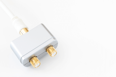
What Is a Stop Valve?

Stop Valves

Stop valves, also known as shut-off valves, are used primarily to control the flow of fluid in a system, allowing for the complete stoppage or resumption of flow. Their application is determined by their function rather than their construction or shape.

These valves find usage across various sectors, including industrial water supply and domestic settings. They are crucial in systems where fluid flow needs to be periodically halted or allowed, such as for maintenance or in emergencies.

Uses of Stop Valves

Figure 1. Example of stop valve use

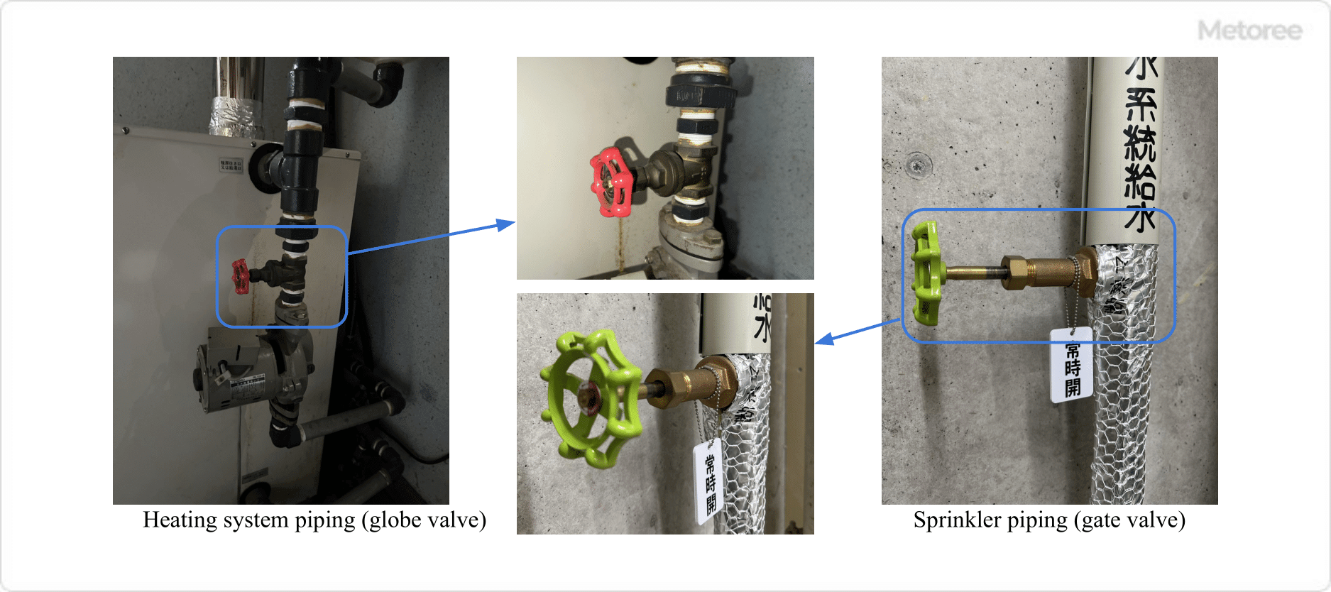
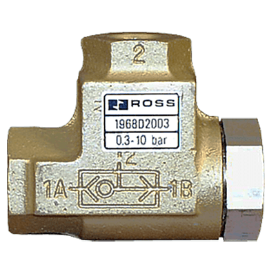
Figure 1: Example of Stop Valve Application

Stop valves are versatile, and used for temporarily shutting off fluids in processes, during maintenance, and in various piping systems in factories, the oil and gas industry, tap water, gas, heating, and sprinkler piping. They are valued for their ability to maintain open or closed states over extended periods.

Principle of Stop Valves

Stop valves have various mechanisms and functions as follows:

1. Shut-off Mechanism

The shutoff mechanism of a stop valve is such that when the handle or actuator is operated, the valve plug is interlocked to shut off or open the flow path. There are two main types of operation:

  • Rotating Action
    The disc, plug, or ball of the valve plug rotates to open or close the valve.
  • Linear Motion
    The disc of the valve plug moves up and down to open or close the valve.

2. Flow Adjustment

Many stop valves are not suitable for precise fluid flow regulation and are not often used for this purpose. However, they may be used in situations where multiple stop valves are installed throughout a piping system, and some of the stop valves are opened and closed to adjust the flow rate of the entire system.

3. Pressure Drop and Shut-off Performance

Stop valves are used for shutting off and opening for long periods and therefore have the following requirements:

  • Long opening time, suitable for constant opening, and low-pressure drop.
  • Long closing time, suitable for constant closing, high shutoff performance, and no leakage.
  • Smooth valve plug motion and low frictional resistance during open/close operation.

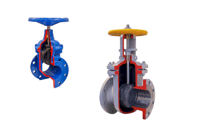
Types of Stop Valves

There are several types of stop valves by mechanism and structure, and the best selection is made according to the operating procedure/frequency and the type of fluid. The types of operating methods include manually operated manual stop valves and remotely operated automatic stop valves.

1. Globe Valve

Figure 2. Globe valve

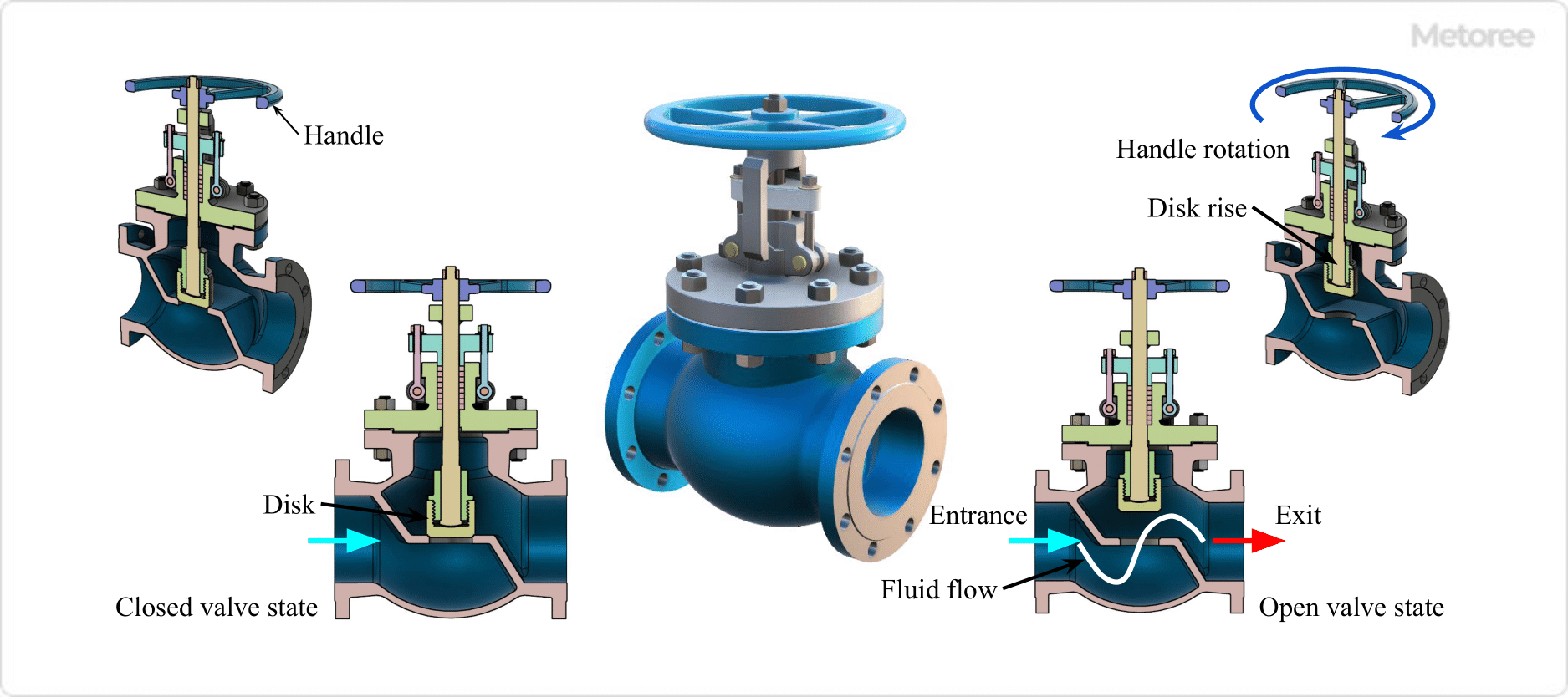
Figure 2. Globe Valve

Mechanism
Globe valves have a linear shutoff mechanism, and the valve plug moves up and down to shut off or open the flow path.

Shape
The valve box (valve body) of a globe valve is spherical, the flow path inside the valve box is curved, and the inlet and outlet are on the same axis. Due to this spherical shape, they are also called globe valves.

Function
Globe valves are used for flow control purposes in addition to on/off applications. The gap size between the valve plug and seat can be changed finely by the amount of rotation of the handle, allowing fine flow adjustment.

However, the disadvantage is a large pressure loss. If the pressure loss needs to be reduced, a gate valve, ball valve, or butterfly valve should be used. Since opening and closing operations cannot be performed quickly, they are mainly used as normally open and normally closed valves. 

2. Gate Valve

Figure 3. Partition valve

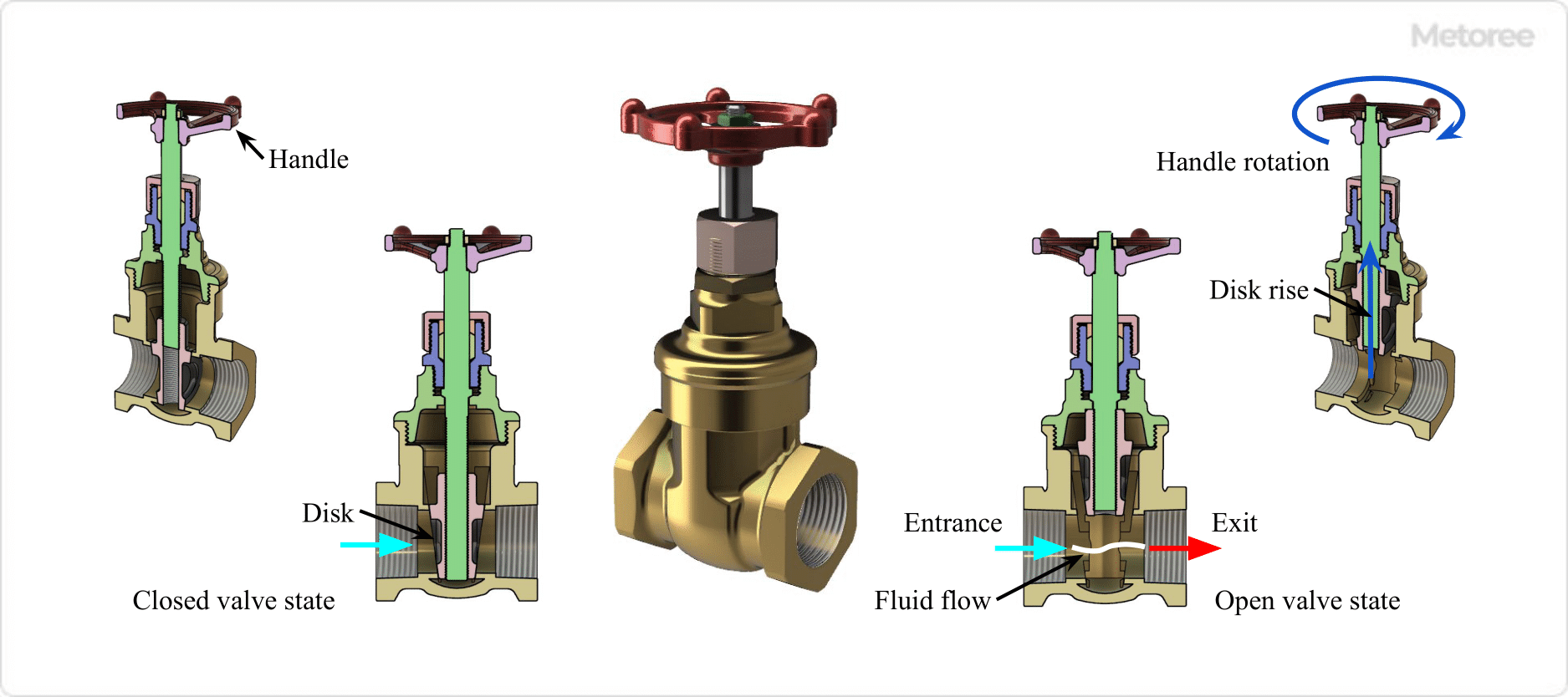
Figure 3. Gate Valve

Mechanism
A gate valve has a linear shutoff mechanism in which the valve plug (gate or wedge) moves up and down to shut off or open the flow path.

Shape
A gate valve has a nearly straight flow path in the valve box, with the inlet and outlet on the same axis. 

Function
The shutoff valve is used for on/off applications where it completely shuts off or opens up. Since the flow path is straight, the pressure loss when fully open is extremely small.

3. Ball Valve

Figure 4. Ball valve

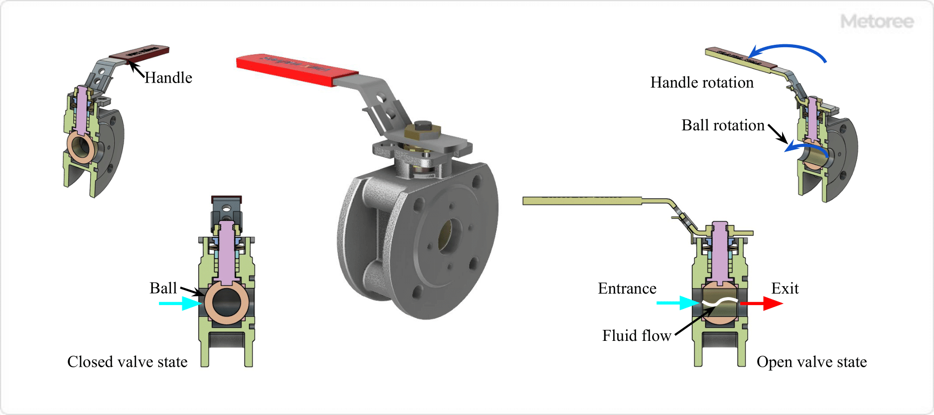
Figure 4. Ball Valve

Mechanism
A ball valve has a rotary shutoff mechanism in which a spherical plug (ball) with a hole in it rotates to shut off or open the flow path.

Shape
In a ball valve, the flow path in the valve housing is nearly straight, with the inlet and outlet on the same axis. Flow occurs when the hole in the center of the plug is aligned with the flow path in the valve box.

Function
Ball valves are quick to open and close. They are primarily used for on/off applications, but some can be used for flow control applications. When fully open, the valve plug does not remain in the flow path, resulting in a small pressure drop.

4. Butterfly Valve Figure 5. Butterfly valve

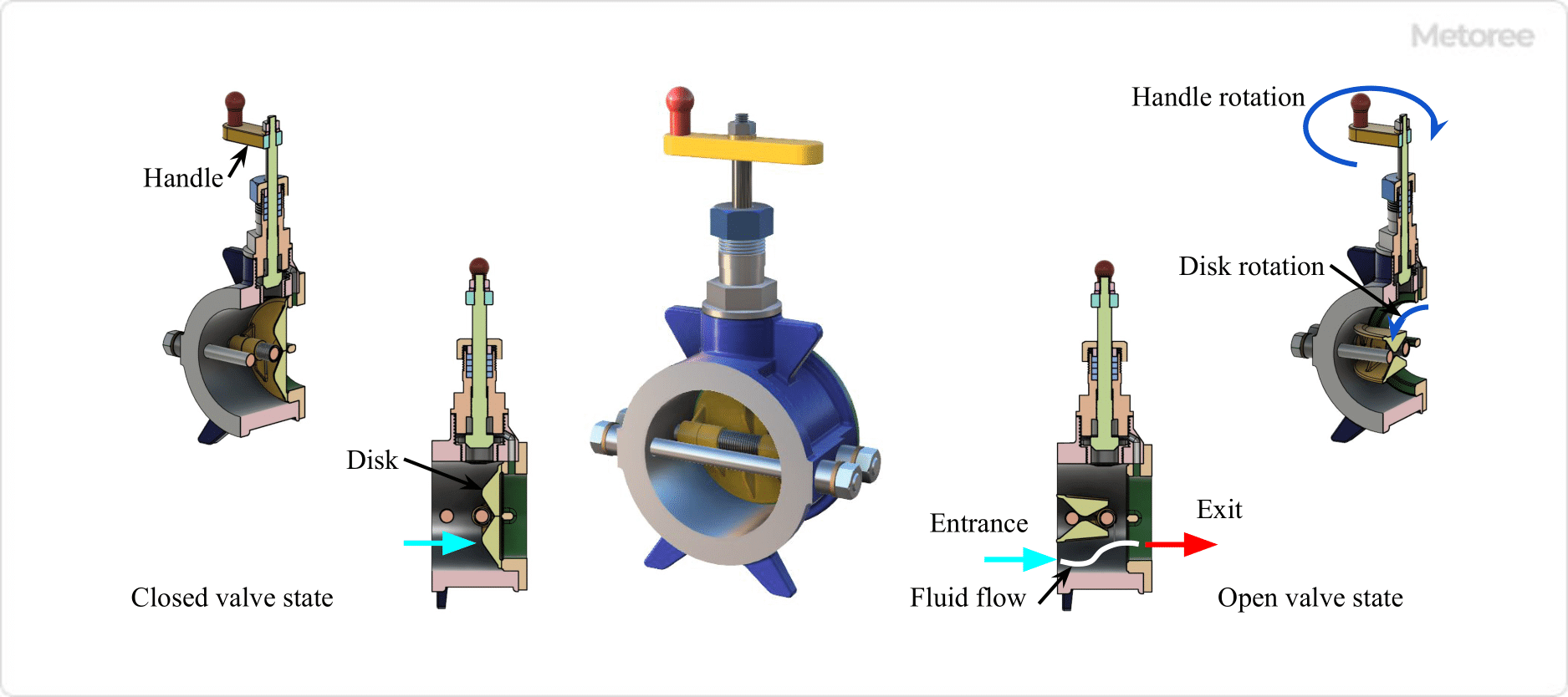
Figure 5. Butterfly Valve

Mechanism
Butterfly valves have a rotary shutoff mechanism that rotates a two-part valve plug to shut off or open the flow path. The valve is called a butterfly valve because the shape and action of the valve disc resemble the wings of a butterfly.

Shape
The valve housing of a butterfly valve is disk-shaped or rectangular. The flow path in the valve box is almost straight, and the inlet and outlet are on the same axis.

Function
Butterfly valves can be opened and closed quickly and are suitable for small to large valve diameters. Although primarily used for on/off applications, the flow rate can be adjusted by the angle of rotation of the valve plug.

Although the valve plug remains in the flow path when fully open, the pressure loss is relatively small.

5. Plug Valve

Figure 6. Plug valve

Figure 6. Plug Valve

Mechanism
A plug valve is a rotary shutoff mechanism in which a cylindrical plug with a hole in it rotates to shut off or open the flow path.

Shape
In a plug valve, the flow path inside the valve housing is nearly straight, with the inlet and outlet on the same axis. Flow occurs when the hole in the center of the plug is aligned with the flow path in the valve box.

Function
Plug valves can be opened and closed quickly and are primarily used for on/off applications. When fully open, the valve plug does not remain in the flow path, and the pressure loss is small.

6. Diaphragm Valve

Figure 7. Diaphragm valve

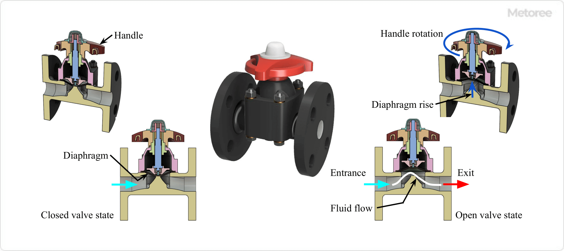
Figure 7. Diaphragm Valve

Mechanism
Diaphragm valves have a linear shutoff mechanism, in which the valve plug (diaphragm) deforms up and down to shut off or open the flow path.

Shape
In a diaphragm valve, the flow path in the valve housing is a gentle curve, and the inlet and outlet are on the same axis. The flow is shut off when the valve plug adheres to the seat and flows when the seat is opened.

Function
Diaphragm valves are used for on/off applications as well as for flow control applications at intermediate openings. They are compatible with corrosive and abrasive fluids and are used in the pharmaceutical, food, and chemical industries.

カテゴリー
category_usa

Shock Resistant Relay

What Is a Shock Resistant Relay?

A shock resistant relay is a safety device that prevents equipment from malfunctioning due to overload.

When a set current value is exceeded, a contact signal is output to stop the equipment. Shock Resistant Relays play an important role in preventing accidents involving property or personnel.

Compared to mechanical safety devices such as shock guards, shock relays have the advantage that they do not require extensive equipment modifications.

Uses of Shock Resistant Relays

Shock resistant relays are safety devices used in conveyors. The following are examples of shock resistant relay applications:

Overcurrent protection devices include circuit breakers and thermal relays, which protect motors and upper circuits. These devices prevent the spread of accidents to higher-level circuits due to motor short circuits and burnout due to overloads. Shock resistant relays, on the other hand, are devices that prevent overloading of conveyors and other loads.

Reduction gear motors are used in chain conveyors and winders. Although the speed of the motor with a speed reducer is low, a strong torque is applied when the load shaft is overloaded. This strong torque may cause chain breakage or equipment failure.

If a foreign object is caught in the chain, it can be recovered in a short time, but if the chain breaks, it is difficult to recover immediately. In addition, if the broken chain recoils and strikes a human body, there is a risk of personal injury. To prevent this, shock resistant relays can immediately detect over-torque and stop the motor.

Principle of Shock Resistant Relays

A shock resistant relay consists of a current transformer, display/control unit, and output unit.

1. Current Transformer

The current transformer is a component that detects the current of the motor. It consists of two coils wound around an iron core, etc. There are integrated types and separate types. The integrated type is used for small capacity motors, while the separately mounted type is used for large capacity motors.

2. Display and Control Unit

The display/control section displays the current value and sets parameters. Rotary switches are often used to set parameters.

3. Output Part

The output part is a component that transmits digital signals of overcurrent to the outside. Relay contact outputs using electromagnetic coils are mainly used. This contact output stops a drive device such as an electromagnetic contactor and shuts off power to the motor.

How to Select a Shock Resistant Relay

Shock resistant relays are often specified in terms of recommended capacity by the manufacturer. If a current transformer is installed separately, match the specifications of the current transformer to the capacity of the motor used.

The type of output signal must also be selected. There are self-holding type and self-resetting type, which should be selected according to the control circuit. For the display, either a digital display or an analog display can be selected. In most cases, digital displays are easier to read, but analog displays are often more robust.

Some products may have functions other than overload. Products that detect and transmit missing phases or unbalance are also available, and products with the required functions are selected.

Other Information on Shock Resistant Relays

How to Use Shock Resistant Relays

Shock resistant relays are electronic control components that are generally sensitive to moisture and dust. Therefore, in most cases, they are stored inside control panels. The most common method of mounting a shock relay inside a control panel is to mount it on a circuit board using a DIN rail or the like.

Inside the control panel, they are connected to the electrical wiring and control circuits of the motor. Wrap the motor’s main circuit wiring around the current transformer and connect the output terminals to the control circuit. If a power supply for shock resistant relay is required, it is generally introduced from the control circuit.

Shock resistant relay settings must also be implemented. The minimum operating current value and operating time must be set, and these should be set by checking the load current and starting current during normal operation.

Depending on the specifications of the shock resistant relay, a secondary current of 0 to 5 A is generally used for the current transformer. In such cases, the operating current is often set around 0 to 6 A while watching the load current. The operating time is generally set between several seconds and several tens of seconds.

カテゴリー
category_usa

Shuttle Valve

What Is a Shuttle Valve?

Shuttle Valves

A shuttle valve, also known as a “double check valve,” is a type of valve with two or more inlet ports and one outlet port. It is commonly used in hydraulic and pneumatic systems to control the direction of fluid flow. The valve automatically connects the outlet to the higher-pressure inlet, ensuring fluid flow from the source with the highest pressure.

Shuttle valves are valued for their ability to easily switch fluid direction for various processes, with a simple structure that contributes to durability and ease of maintenance.

Uses of Shuttle Valves

Shuttle valves are employed in several applications for fluid directional control, including:

1. Hydraulic Units

They play a crucial role in hydraulic systems, directing fluid from hydraulic pumps to cylinders and motors, allowing for precise control of movement and operations.

2. Transportation Equipment

In transportation, shuttle valves are integral to hydraulic braking systems in vehicles like cars and trains, controlling the flow of hydraulic fluid to apply braking pressure effectively.

3. Chemical Plants

In chemical manufacturing, shuttle valves are used to mix fluids from different sources accurately, ensuring the correct chemical formulation for processes.

Principle of Shuttle Valves

Shuttle valves operate using a movable element or shuttle within the valve body, which shifts based on fluid pressure to connect either of the inlet ports to the outlet port. This mechanism allows for the automatic selection of the fluid path based on pressure changes, ensuring a continuous flow through the valve.

Materials like aluminum for the valve body and nylon or synthetic rubber for the valve plug are commonly used, with the design prioritizing simplicity, reliability, and flexibility in control processes.

How to Select a Shuttle Valve

The selection of a shuttle valve should consider factors such as the fluid type, operating pressure, connection bore size, and material compatibility to ensure optimal performance and safety in its intended application.

1. Fluid to Be Used

Select valves compatible with the specific characteristics of the operating fluids, considering factors like corrosion, temperature, and viscosity.

2. Operating Pressure

Choose a valve that can withstand the system’s maximum pressure to avoid damage or safety hazards.

3. Connection Bore

The bore size should match the system’s piping, with common connection types including screwed connections like Rc and NPT.

4. Material

Select materials based on fluid compatibility and environmental conditions, with options ranging from stainless steel and brass to aluminum and plastic.

カテゴリー
category_usa

Electric Cutout

What Is an Electric Cutout?

Electric cutouts are small switchgear designed to cut off electricity.

It is often used especially for high voltage, such as 6,600V or 3,300V, and is also called a high voltage cutout. The Electric Cutout’s case is made of highly insulating porcelain, and opening the lid of this case opens the circuit.

A fuse is built inside to prevent the large current that flows in the event of a short circuit from spreading to the upper circuits.

Uses of Electric Cutouts 

Electric cutouts are often used in high-voltage distribution lines. The following are examples of electric cutout applications:

  • Upstream side of a pole transformer
  • Upstream of indoor transformers
  • Upstream of an arrester
  • Upstream of phase advance capacitor

Cutouts are installed to interrupt the accidental current flowing upstream in the event of a failure of downstream equipment. Electric cutouts are also used to open the circuit during construction and maintenance to interrupt the voltage supplied to the equipment and prevent electric shock to workers.

Principle of Electric Cutouts

A box-type electric cutout, one of the most commonly used cutouts, consists of a main body, lid, and fuse/fuse links.

1. Main Body

Electric cutout bodies are made of porcelain, which has high insulation and weather resistance. Therefore, little deterioration occurs even after long-term use. The porcelain body has mounting bolts embedded in it, which are used to attach the cutout to a base or column.

The main body also has wire entry ports on the top and bottom, which are firmly connected to the fuse links with internal terminals. 

2. Lid

The lid is connected to the main body with hinges. Hooks are attached to the surface of the lid, and the circuit can be opened with an operating hook rod or similar. A fuse or other device is mounted inside the lid and can be replaced by opening the circuit.

3. Fuses and Fuse Links

A fuse is a component installed to interrupt a circuit in the event of a short circuit in downstream wiring. The fuse contains a fuse element and silica sand. In the event of a short circuit, the fuse element breaks the wire and the silica sand quenches the arc to provide protection.

The fuse links are fitted with blades (contact blades), which are inserted into the fixed electrode terminals of the body to conduct the circuit.

Types of Electric Cutouts

Several types of electric cutouts are available, depending on the situation and installation location.

1. Double Fuse Type Cutout

Double fuse electric cutouts have two current-limiting fuses inside. If the first cutout is disconnected due to overcurrent, the second cutout is automatically connected. This can prevent power failure even in the event of a temporary overcurrent due to lightning or other causes.

 2.Vibration-Resistant Cutout

Vibration-resistant electric cutouts are designed to be resistant to vibration. Electric cutouts are characterized by their ability to hold fuses and lids better than normal electric cutouts. They are used in locations where vibration is expected, such as on cranes. 3.

3. Salt-Resistant Cutout

Electric cutouts are used in areas where salt damage occurs, such as at the seaside. The withstand voltage value when salt adheres to the surface is called the stain resistance characteristic. The salt-resistant cutout is characterized by its high stain resistance.

The internal structure of electric cutouts is no different from that of ordinary cutouts. However, packing is installed at the wiring entry port and at the joints with the lid to prevent salt from entering. 

4. Cylindrical Cutout

Cylindrical electric cutouts have a fuse inside the cylindrical insulator. It is used for feeding power to trains, etc. The current-limiting fuse can be pulled out from the bottom of the cylinder.

Other Information on Electric Cutouts

Life Span of Electric Cutouts

Electric cutouts deteriorate over time due to exposure to the elements and ultraviolet rays. The life expectancy over time is 10 to 15 years.

The number of times the load current can be opened and closed is limited to about 50 to 100 times, and the number of times the short-circuit current can be interrupted is limited to about 5 times. Therefore, it is recommended to open them under no-voltage or no-load conditions whenever possible for maintenance and other purposes.

Note, however, that the above is only a guideline, and the service life may vary depending on the installation environment and usage conditions.

カテゴリー
category_usa

Counterbalance Valve

What Is a Counterbalance Valve?

A counterbalance valve is a hydraulic control valve that restricts flow from one side while allowing free flow from the other. It plays a crucial role in preventing hydraulic cylinders from unexpectedly and rapidly lowering, thus ensuring the safety of operators and bystanders. This is particularly vital when handling large loads or working at heights. Counterbalance valves can be adjusted and configured to meet specific requirements and are customizable for various applications.

These valves are integral to many construction and machine tools, enabling them to provide significant power on a small scale. When combined with electrical circuits, counterbalance valves can be utilized in a wide range of applications.

Uses of Counterbalance Valves

Counterbalance valves are employed in numerous hydraulic system applications, including:

1. Construction Machinery

In construction machinery such as excavators and bulldozers, counterbalance valves enhance safety and control by managing the lifting and lowering of large loads, such as controlling the boom of cranes to prevent unexpected lowering.

2. Agricultural Machinery

Counterbalance valves are integrated into the hydraulic systems of agricultural tractors, assisting in the control of farm tools and attachments, thereby making fieldwork and mowing more efficient and manageable.

3. Industrial Machinery

In industrial presses used for forming metals and plastics, counterbalance valves control vertical movement, supporting precise forming processes and ensuring safety and control in valve operations.

4. Aircraft

Counterbalance valves are crucial for the safe and reliable operation of aircraft during takeoff and landing, controlling the retraction and deployment of the landing gear and absorbing landing shock.

Principle of Counterbalance Valves

Counterbalance valves consist of a valve body, plug, spring, and ports, with the spring applying a set pressure that determines when fluid is allowed to pass. These valves maintain a balancing point of pressure that supports loads, such as cylinders, adjusting fluid flow to lift loads or prevent unexpected lowering.

How to Select a Counterbalance Valve

Selecting the right counterbalance valve involves considering factors such as fluid type, pressure adjustment range, and maximum working pressure to ensure the valve meets system requirements and operates safely.

Additional Counterbalance Valve Information

1. Difference Between Counterbalance Valve and Pilot Check Valve

While both counterbalance and pilot check valves provide directional control, counterbalance valves also control flow, distinguishing them from pilot check valves which only control direction and prevent spontaneous operation of system components.

カテゴリー
category_usa

Escapement

What Is an Escapement?

An escapement is a mechanism or device designed to regulate the movement or flow of products or components, particularly in automated systems. Its primary function is to separate or divert items moving in a stream, commonly on a conveyor, in industrial production lines according to specific criteria.

Outside of industrial contexts, the term ‘escapement’ is also used in various fields, each with unique mechanisms suited to their specific applications. For example, in the music industry, it refers to the mechanism in electronic pianos that mimics the feel of an acoustic piano’s action. In mechanical watches, ‘escapement’ denotes the component regulating the timekeeping system.

Uses of Escapements

In automated production lines, escapements are essential for sorting and routing products or parts based on pre-set configurations. They can also be employed for quality control by signaling and removing defective products from the production flow. These mechanisms are vital in maintaining the efficiency and accuracy of automated processes.

How to Select an Escapement

Choosing the right escapement depends on various factors, and the selection process generally involves:

  1. Confirmation of Usage Conditions: Determine if the escapement will handle objects moving horizontally or vertically. Key parameters include operating pressure, mass and number of workpieces, stroke, conveyor speed, friction coefficient (for horizontal movement), drop distance, and gravitational acceleration (for vertical movement).
  2. Confirmation of Impact Force: Using a graph that plots conveyor speed against workpiece mass (with stroke as a parameter), ensure that the planned environment falls within the escapement’s operational range for both horizontal and vertical applications.
  3. Confirmation of Allowable Lateral Load: Refer to a graph that plots stroke against lateral load (with operating pressure as a parameter). It’s essential to pre-calculate the lateral load, which can be derived from the friction coefficient, total mass, and gravitational acceleration for horizontal applications, and solely from total mass and gravitational acceleration for vertical applications.
カテゴリー
category_usa

Exhaust Valve

What Is an Exhaust Valve?

Exhaust Valves An exhaust valve is a device designed to release air, commonly used in pneumatic systems to efficiently discharge compressed air from the piping. Due to its ability to expel large volumes of air rapidly, it is often referred to as a quick exhaust valve or rapid exhaust valve. In automotive contexts, the term ‘exhaust valve’ refers to the component responsible for expelling combustion gases from an engine’s cylinder, distinct from an intake valve that allows air or a fuel mixture into the cylinder.

Uses of Exhaust Valves

Exhaust valves are crucial in pneumatic circuits, especially where rapid expulsion of compressed air is necessary. They are typically used in conjunction with air cylinders to facilitate high-speed operations. When connected to the supply and exhaust ports of an air cylinder, these valves enable the rapid release of air without relying on solenoid valves, enhancing the cylinder’s speed and efficiency.

Principle of Exhaust Valves

Exhaust valves feature three ports: IN (compressed air supply side), OUT (cylinder side), and EX (open to atmosphere), along with an internal valve mechanism. When compressed air flows from IN to OUT, the internal valve closes the EX port, linking IN and OUT. Conversely, when air flows from OUT to IN, the valve closes the IN port, connecting OUT to EX for swift exhaust.

The effectiveness of these valves in enabling high-speed cylinder movement depends on factors such as the flow rate of compressed air, the cross-sectional area of the piping, and the air pressure. Therefore, the selection of surrounding equipment is crucial to ensure optimal performance.

In applications where the exhaust valve functions as an OR valve, the IN and EX ports serve as inputs, with the OUT port acting as the output.