カテゴリー
category_usa

Bipedal Robots

What Is a Bipedal Robot?

A bipedal robot is a robot characterized by having a torso and two independently operating arms. This design allows for complex tasks to be performed, offering more human-like movements compared to single-armed robots. Bipedal robots can work with objects in floating positions, unlike their single-armed counterparts.

Uses of Bipedal Robots

Bipedal robots are employed in various industries including manufacturing, logistics, and food service, as well as in medical and welfare facilities. They are also used in academic research. Two main types based on joint structures are vertically articulated robots and horizontally articulated robots, sometimes referred to as SCARA robots.

1. Vertically Articulated Robots

Suitable for three-dimensional work, these robots perform tasks such as machining, polishing, inspection, painting, welding, assembly, picking, and handling.

2. Horizontally Articulated Robots

Designed for flat surface work, these robots are commonly used for inspection, assembly, and handling tasks.

Principle of Bipedal Robots

Bipedal robots operate similarly to conventional robots, consisting of hands, arms, and joints. Vertically articulated models typically have six or more axes, allowing movement in three-dimensional space. Some even mimic human form with additional axes. Horizontally articulated robots generally have four axes, with three for horizontal movement and one for vertical action. These robots use servo motors for precision and are often equipped with multiple cameras and force sensors for autonomous capabilities.

Other Information on Bipedal Robots

1. About the Price of Bipedal Robots

Previously expensive, the cost of bipedal robots has decreased, making them more accessible for use in various sectors. Modern models are also lighter and safer, meeting the growing market demand.

2. Advantages of Bipedal Robots

Bipedal robots offer several advantages, including the ability to perform complex tasks, high safety standards, and reduced introduction costs. They can work alongside human workers, even in settings that previously required safety fences for robots with higher power outputs. This flexibility, combined with their decreasing cost, makes them a valuable asset in various industries, improving work efficiency and reducing labor costs.

カテゴリー
category_usa

What Is Thermal Interface Material?

What Is Thermal Interface Material?

Thermal Interface Material

Thermal Interface Material (TIM) is crucial in managing heat in devices, especially with the increasing performance and miniaturization of products. TIMs are used to protect products from heat by facilitating efficient heat transfer.

With the sophistication of electronic devices, heat management becomes critical. Without adequate heat dissipation, there can be impacts on product performance and even risks to mechanical integrity and human health. As devices miniaturize, their ability to dissipate heat reduces since heat can only escape from surfaces.

Traditional methods like natural air cooling are reaching their limits, and as a result, innovative heat dissipation methods are becoming increasingly important.

Heat dissipation typically occurs from the surface area of components. However, as components shrink in size, their surface area decreases, leading to heat aggregation. This is evident in components like capacitors, diodes, and transistors on electronic circuit boards, where the heat generated can affect surrounding components.

The relationship between substrates and components has evolved, with current components having smaller surface areas and hence transferring more heat to the substrate, affecting adjacent components even in cooler ambient air.

TIMs are designed to address these challenges.

Applications of Thermal Interface Material

TIMs are used across various industries, especially in electronic components. They include thermally conductive materials (TIMs) and heat sinks, with TIMs being used for smaller products and heat sinks for larger ones.

  • Thermal Interface Material (TIM)
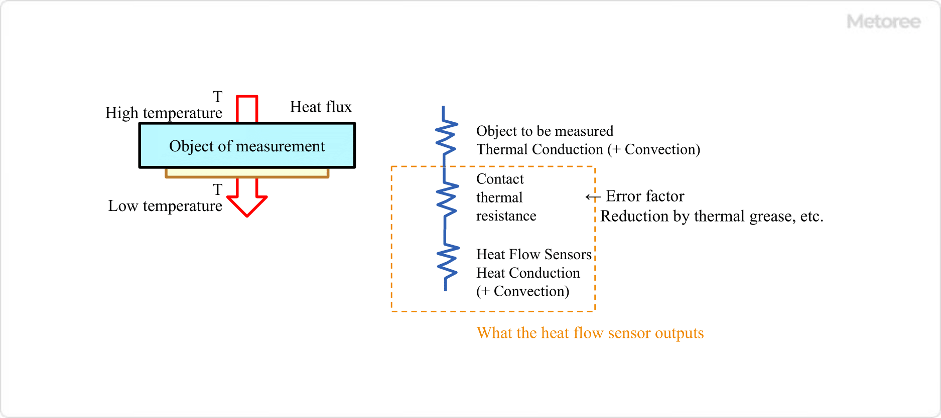
    TIM, or Thermal Interface Material, is a heat-conductive material placed between components to dissipate heat. It reduces thermal resistance caused by an air layer between the heat source and the cooler, thus facilitating efficient heat transfer. Common materials for TIMs include boron nitride, aluminum nitride, alumina, and carbon-based sheets, as well as heat-dissipating grease.
  • Heat Sinks
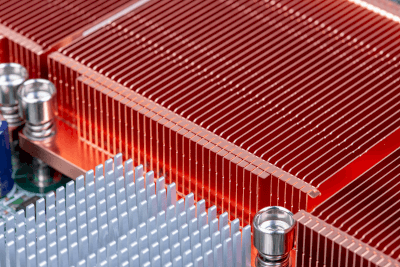
    Heat sinks are designed to dissipate heat efficiently and typically consist of fins or plates with a large surface area. They are used in applications where space allows for a large surface area.

How to Select Thermal Interface Material

The selection of TIMs is based on thermal design principles. Designers consider factors like total heat generation, allowable temperatures, dimensional restrictions, and the environment where the equipment will be installed. It is crucial to ensure compatibility of the TIM with the conditions of the installed equipment to avoid any unintended interference or accidents.

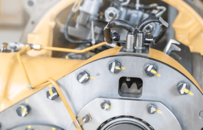
In the automotive industry, for example, TIMs are used in metal and molded plastic parts, but careful selection is necessary to prevent interference with radio wave transmission in electronic devices.

Types of Thermal Interface Material

TIMs include not only thin materials like sheets but also heat pipes, vapor chambers, heat-dissipating coatings, fans, and grease. These materials are used in various applications, from personal computers to automotive parts, and are chosen based on specific requirements like thickness, solubility, and thermal radiation properties.

  • Heat Pipes
    Heat pipes use the latent heat of evaporation of a working fluid to transport and dissipate heat. They are maintenance-free and used in a variety of applications.
  • Vapor Chamber
    Vapor chambers work similarly to heat pipes but are thinner and smaller, suitable for applications like smartphones and smart glasses.
  • Heat Dissipating Coatings
    These coatings dissipate heat by radiating it as electromagnetic waves rather than relying on the thermal conduction efficiency of the paint film. They are used in motors, engines, exhaust products, lighting, and heat sinks.
  • Heat Dissipation Fan
    Using forced-air cooling, these fans are mainly used in computers, servers, power supplies, and power distribution boards.
  • Heat-dissipating Grease
    Thermal grease improves thermal conductivity and is used to lower thermal resistance, often referred to as CPU grease.

原薬の定性・定量分析

原薬の定性・定量分析とは

原薬の定性・定量分析 (英:qualitative & quantitative analysis of drug substance) とは、医薬品の有効成分である原薬を定性・定量分析することです。

定性分析は、化学分析の1つで、試料中に含まれる各種の成分の種類を知るための分析法です。未知物質を分析する際に最初に行う分析です。

また、定量分析は 、試料中に含まれる各種の成分の量を求めるための分析法です。一般に定性分析でその成分を明らかにしてから行います。

原薬の定性・定量分析の使用用途

原薬の定性・定量分析は、原薬の開発時や製造工程で多く使用されます。

開発段階では、厚労省の「医薬品の元素不純物ガイドラインについて」や日本薬局方の対象元素、塩原薬の目的元素などを、簡便・迅速に分析するために使います。また、受入れおよび出荷時には、製造工程での異物混入や触媒残渣を確認することも重要です。

原薬の定性・定量分析の原理

1. 定性分析

定性分析の方法は、物質中に含まれる特定化学種の特有な化学反応及び物理的性質などを調べて,既知のものと比較して確認します。

化学反応を利用するものは湿式分析が多いが、炎色反応・ほう砂球反応・吹管分析なども簡単な定性分析として利用されます。もっとも素朴な方法は、視覚や臭覚など人間の感覚を利用します。

主として水溶液の化学変化を利用する湿式法には、有機・無機物質の系統的定性分析法が多数あります。無機化合物を対象としたものは乾式法とよばれます。

物理的性質には、色・融点・沸点・電導度・結晶形・比重・磁性・誘電率・屈折率・スペクトルなどがあります。電磁波スペクトルによる方法が一般に利用されています。

2. 定量分析

定量分析の方法には、化学的、物理的、あるいは両者の併用による方法があります。

化学的定量法の中で、容量分析法や重量分析法は、特殊な機器を使用しないのでよく使われます。

一方、物理的定量法には光学的・電気的・磁気的・その他数多くの方法があり、それぞれが、分析成分と特異な相互作用をすることを利用しています。

高価な分析機器を使用して分析する場合が多いが、簡便・迅速な方法なので、機器による定量分析が大部分を占めています。

具体的には、吸光光度法・X線分析法・発光分光分析法・原子吸光分析法・電解分析法・クロマトグラフ法・放射化分析法などがあります。また、光度滴定・同位体希釈分析・質量分析・核磁気共鳴分析・ポーラログラフィー・クーロン滴定・ガス分析・比色分析・電解分析などの方法が数多くあります。

試料の量は 0.1~1g程度のものが多いが、1~10mg程度を用いて定量分析を行う場合は,微量化学分析またはミクロ分析と呼ばれます。

また、物理化学的定量法は、化学反応生成物の物理的性質を測定して定量を行う方法です。

原薬の定性・定量分析の規制

医薬品原薬は、有機合成・発酵・天然物からの抽出などにより作られる化学物質です。医薬品の有効成分として、品質・有効性・安全性の保証が必要です。

開発段階では、安全や環境を守るため、「化学物質の審査及び製造等の規制に関する法律(化審法)」や「労働安全衛生法」の対象となります。

医薬品としては、「医薬品、医療機器等の品質、有効性、安全性の確保等に関する法律(医薬品医療機器等法)」の適用を受けます。

原薬製造業者は、医薬品医療機器等法にしたがって、製造所毎に厚生労働大臣の許可を受ける必要があります。

原薬の定性・定量分析装置

原薬の開発及び製造工程では、様々な目的で元素分析を行います。開発段階では、特定の元素などを目的として行います。また、製造工程では、製造中の異物混入や触媒残渣などを確認します。

分析には、多くは蛍光X線分析装置を使用します。蛍光X線分析装置により、試料にX線を照射し、発生する蛍光X線の強度やエネルギーを解析して、試料を構成する元素の種類や含有量を調べる装置です。非破壊で固体・粉体・液体などの元素分析ができます。

触媒残渣の分析では、試料0.1g程度で、不純物に指定されている元素の定量分析が検量線法により可能です。また、塩原薬の分析では、塩原薬のカウンターイオンを構成する元素を定量することで、分子数の確認ができます。

原薬の製造工程では、異物分析を行います。異物の大きさは数十µmから分析が可能で、金属やガラス片などが検出できます。

結晶多形分析

結晶多形分析とは

結晶多形分析 (英:polymorph analysis) とは、同一の化学組成を有する化合物で結晶構造の異なるものである結晶多形を分析することを言います。

同一元素での結晶多形は,ダイヤモンドとグラファイトの例がよく知られています。どちらも炭素のみから構成されますが、結晶構造が異なっており、物質としては全く違う性質を有します。

分析手法には、X線回折・熱分析・赤外分光・ラマン分光・固体核磁気共鳴などがあります。

医薬品の開発などでは、結晶多形分析が重要なツールとなります。

結晶多形分析の使用用途

結晶多形分析は、医薬品の評価に多く使用されます。医薬品の多くは結晶であり、複数の結晶形を有しています。同一の組成でも結晶形により溶解性などの物理化学的な性質が異なり、医薬品の有効性や安全性にも影響があります。

そのため、結晶形の同定が非常に重要です。1つの方法は、X線回折 (XRD) を使用して、医薬品の結晶多形を分析する方式です。X線を対象物に入射させて、スペクトル図から、結晶多形を見つけます。

また、油脂類の結晶多形分析が行われています。例えば、チョコレートでは安定形結晶多形のV型、マーガリンでは準安定形結晶多形などがあります。結晶多形現象の解析などが重要です。 

結晶多形分析の原理

結晶多形分析は、X線回折・熱分析・赤外分光・ラマン分光・固体核磁気共鳴などの手法があります。この他、赤外線吸収スペクトル法や偏光顕微鏡法などによっても結晶多形を確認できます。

1. X線回折

X線回折 (XRD) は、結晶性物質にX線を入射すると各原子がX線を散乱し、その物質特有の散乱スペクトルを取得する方法です。

XRDによる回折パターンの違いから結晶多形を判別をします。例えば、α型は単斜晶、γ型は六方晶の結晶です。XRDでピーク面積を解析することで、結晶化度が算出できます。

2. 熱分析

熱分析 (DSC、TGなど) は、物質を加熱または冷却して、物質の物理的な変化を調べる手法です。
 
DSC (Differential Scanning Calorimeter) 示差走査熱量計 により、温度変化に対する熱量を測定して、融解・分解等の熱挙動から、結晶多形を判別します。

TG (Thermogravimetry) 熱重量は、吊り下げ方式・上皿方式・水平方式などの熱天秤を使用して、温度変化に対する重量を測定します。

DTA (Differential Thermal Analysis) 示差熱分析は、TGの結果と合わせて、吸熱や発熱を検出し、分解・脱水・燃焼・昇華・蒸発・酸化・融解・結晶化などの諸反応を正確に把握できます。

3. ラマン分光

ラマン分光は、物質に光を入射すると、入射光とは波長が異なる微弱なラマン散乱光が発生します。これを分光分析して、物質の分子構造や結晶構造などを調べる手法です。

ラマン分光測定結果から、結晶多形を識別します。比較的微量で測定が可能です。

4. 固体核磁気共鳴

固体核磁気共鳴 (固体NMR) は、核磁気共鳴 (NMR、Nuclear Magnetic Resonance) 分光法の一種で、有機化合物・医薬品・蛋白・無機化合物の構造解析・組成分析に使用します。

医薬品の結晶多形技術

1. 製剤技術

新薬の開発に伴い、新しい製剤技術開発も推進されています。経口製剤の場合、体内で医薬品の有効性を高めるには、医薬品結晶が消化液に早く溶けるのが第一です。これには、結晶多形の利用が微粉化と並んで、重要な役割をします。

薬の溶解性は、準安定形結晶の方が安定形結晶より、優れている場合が多いとされています。結晶多形を利用して、準安定形結晶を製造する技術開発が行われています。

2. 製造プロセス

医薬品の約80%に結晶多形が存在すると言われています。結晶多形は、医薬品の安定性・溶解性などに重大な影響を与えます。製造プロセスの開発では、目的の結晶多形を作り出す目的で、結晶多形のスクリーニングを行います。

医薬品の開発途中で新たな結晶多形が見つかると、その対処のため、開発日程に大きく影響します。また、プロセスに悪影響を及ぼす結晶多形もあり、品質管理面での管理技術も必要になります。さらに、新薬の発売後に、新たな結晶多形が突然発生することもあります。

カテゴリー
category_usa

Heat Flux Sensors

What Is a Heat Flow Sensor?

Heat Flux Sensor

Figure 1. What is a heat flow sensor?

A heat flux sensor is a device used to measure the amount of heat transfer, also known as heat flow. Heat generally moves from an area of higher temperature to a lower temperature. By measuring this heat flow, the amount of heat transfer can be quantified, and subsequent temperature changes can be estimated.

These sensors convert the heat passing through them into an electrical signal. They are available in flexible designs for curved surfaces and waterproof versions, suitable for various applications.

Applications of Heat Flux Sensors

Heat flux sensors are commonly used in evaluating the thermal insulation performance of housing equipment. With advances in miniaturization and flexibility, their usage has expanded beyond housing applications to include areas such as electronic components and automotive engineering, where they help monitor heat dissipation and loss.

For example, these sensors can be installed inside electronic components to measure the heat they generate. In automobiles, they are used for evaluating heat loss in engine compartments, seat heaters, and air conditioners. Additionally, heat flux sensors are instrumental in measuring the amount of heat flow in and out of materials during phase changes. One innovative application involves enclosing the material to be measured in a bag-shaped heat flux sensor. This setup allows for the measurement of heat flow in and out of the object and can be coupled with a cooling agent to monitor cooling capacity and duration.

Principle of Heat Flow Sensor

Heat Flux Sensor Principle

Figure 2. Principle of heat flow sensor

Heat flux sensors operate based on Fourier’s law and the Seebeck effect. Fourier’s law indicates that heat flow per unit area and time is proportional to the temperature gradient. The Seebeck effect generates a voltage when a temperature difference is applied across a substance.

The internal structure of these sensors typically includes N-type and P-type semiconductors, which exhibit the Seebeck effect, and thermocouple materials like copper and chromel-alumel connected in series. This configuration amplifies the small voltage generated by each component, enabling effective detection of heat flow.

Other Information on Heat Flow Sensors

How to Use Heat Flow Sensors

Using a Heat Flow Sensor

Figure 3. How to use a heat flow sensor

Proper selection and installation of heat flux sensors are crucial. It’s important to adhere to the specified temperature range limits to avoid issues like adhesive surface peeling. Sensors should be securely attached to the measurement object, using high-conductivity adhesives or silicon grease to minimize errors due to contact thermal resistance.

Before installation, it’s necessary to ensure that no air or foreign matter is trapped under the sensor and to check the direction of heat flow and the polarity of the sensor’s output by applying a temperature difference.

カテゴリー
category_usa

Speed Sensors

What Is a Speed Sensor?

Speed Sensors

Speed sensors are installed in vehicles such as automobiles, motorcycles, railcars, ships, and aircraft. They can detect and measure the speed at which these vehicles are moving.

Speed sensors include those that determine speed based on the angular velocity of the wheels (how much the wheels turn per unit time), those that use the Doppler effect, or the phase shift between reflected light and sound waves. There are also those that use pitot tubes to measure the speed of fluid objects such as air and water, and GPS speedometers that use signals sent from satellites in orbit.

Uses of Speed Sensors

Speed sensors, as mentioned above, are used to detect and measure the speed of movement of various types of vehicles.

However, since vessel operations are generally subject to numerous external forces and are complex and varied, and require careful maneuvering in ports and harbors, speed sensors are installed in various parts of vessels as follows:

When large vessels berth, it is necessary to control the inertia of the huge hull to optimize the berthing speed.

The vessel berthing speed meter measures the berthing distance and speed at the bow and stern, respectively, and displays data such as berthing speed and angle to assist in safe berthing.

Unlike land vehicles, aircraft cannot measure ground speed but instead use pitot tubes to measure airspeed, which is the speed relative to the air.

Accurate measurement of airspeed (the speed at which the wing overtakes the air) is the most important indicator for understanding lift, which is a factor in flight continuity.

Principles of Speed Sensors

Speed sensors that utilize the Doppler effect are used to measure water speed on ships.

The Doppler effect refers to a phenomenon in which when a sound source (note: radio waves and light cannot be used underwater because they are significantly attenuated compared to ultrasonic waves) and a sensor are relatively close to each other. The frequency is perceived to be higher than when there is no relative motion, and when they are moving away from each other, the frequency is perceived to be lower.

This frequency shift, or Doppler shift of water particles, is used to calculate water velocity.

In aircraft, airspeed is measured by a pitot tube mounted on the fuselage.

The pitot tube draws air in through a hole in its tip and measures airspeed using the difference between the wind pressure from outside and the atmospheric pressure at that location.

In actual passenger aircraft, pitot tubes are used to estimate airspeed, which is then corrected using a computer to obtain a more accurate airspeed for use in flight.

カテゴリー
category_usa

Multiple Spindle Drilling Machinery

What Is Multiple Spindle Drilling Machinery?

Multiple spindle drilling machinery is a type of machining tool that uses multiple drill bits simultaneously. Unlike typical drilling machines that utilize a single bit, this machinery enhances productivity by enabling simultaneous machining with several bits. This capability is particularly efficient for complex hole patterns and surfaces. However, the operation of multiple spindle drilling machinery requires careful attention to the dimensional and positional accuracy of the workpiece.

Uses of Multiple Spindle Drilling Machinery

Multiple spindle drilling machinery is used in various applications, such as:

  • Hole Drilling: In manufacturing watch gears, pins, artificial joints, and engine parts.
  • Cutting: For cutting metal and plastic parts.
  • Engraving: In furniture manufacturing and jewelry design.
  • Milling: Cutting grooves and precision holes in electronic circuit boards.
  • Grinding: In the manufacturing of watches, bearings, and similar items.

Principle of Multiple Spindle Drilling Machinery

Multiple spindle drilling machinery operates by securing the material using a clamp or vise, selecting the appropriate cutting tools like drill bits, end mills, and reamers, setting cutting conditions, and precisely positioning the holes. The machinery controls multiple axes for accurate positioning and uses coolant and lubricant to reduce friction and overheating during machining.

Structure of Multiple Spindle Drilling Machinery

The structure of multiple spindle drilling machinery includes a motor as the power source, rotary shafts driven by motors, belts connecting the motors and shafts, a table for mounting materials, various cutting tools mounted on the rotary axis, and a control unit for adjusting speeds and settings.

Other Information on Multiple Spindle Drilling Machinery

1. Advantages

Advantages include increased efficiency from simultaneous drilling, consistent hole positioning for precision machining, and versatility in hole machining.

2. Disadvantages

Disadvantages encompass the need for larger space, operational complexity, limited drilling capabilities due to fixed spindle positions, and higher costs and maintenance requirements.

3. Productivity Improvement

Incorporating multiple spindle drilling machinery into automated production lines can significantly enhance productivity. Automated features such as changing cutting tools and table movement, along with computer control for managing machining conditions and inspecting results, improve efficiency and quality on the production line.

カテゴリー
category_usa

Weathering Testers

What Is a Weathering Tester?

Weathering testers are devices used to evaluate the degradation of products exposed to natural environmental factors such as solar radiation, rainfall, temperature, and humidity. Commonly used in industries involving materials like plastics, paints, fibers, and paper, these testers conduct accelerated testing to confirm material durability over a shortened period.

Weathering resistance testing, governed by standards like JIS (Japanese Industrial Standards) and ISO (International Organization for Standardization), is crucial in product design and pre-market evaluation phases, and sometimes just before shipment.

Uses of Weathering Testers

Weathering testers are vital for products intended for long-term use in natural environments, including materials like paint, plastics, rubber, textiles, and paper, as well as automobiles, buildings, and home appliances. These testers are especially important for products prone to degradation due to light, temperature, and humidity.

Principle of Weathering Testers

These testers simulate environmental factors like light, temperature, and humidity to accelerate the deterioration process. They use light sources such as xenon lamps, which closely mimic sunlight across various wavelengths, or carbon arc lamps, known for their strong UV emission. By combining these light sources with controlled temperature and humidity settings, weathering testers effectively evaluate product durability in simulated natural conditions.

Types of Weathering Testers

1. Xenon Weather Meter

This tester uses a xenon arc lamp to simulate sunlight and includes features like temperature and humidity control and simulated rainfall. It’s widely used for testing polymer building materials, and anodic oxide coatings on aluminum, paints, plastics, and rubber, as specified by JIS.

2. Sunshine Weather Meter

An older but still relevant tester, the Sunshine Weather Meter uses a carbon arc lamp, offering high UV energy. Though less sun-like than xenon lamps, its historical data make it a valuable tool in evaluating industrial coatings and other materials under accelerated weathering conditions.

3. Ultraviolet Fluorescent Lamp Weather Meter

Used mainly for evaluating the weather resistance of coating films, this tester employs ultraviolet fluorescent lamps to assess effects like cracking and chalking through cyclic testing.

4. Ultraviolet Fade Meter

The ultraviolet fade meter focuses on evaluating fading or discoloration caused by sunlight. It is particularly used for testing automobile interior materials and textile products, using a carbon arc lamp as its light source.

カテゴリー
category_usa

Boring Machinery

What Is Boring Machinery?

Boring Machinery

Boring machinery is a machine tool specialized for a process called boring.

Boring is the process of enlarging a hole drilled with a drill, etc., by expanding the hole. Boring is used to make larger holes that cannot be drilled, or when accurate dimensioning and finishing are required.

Boring can be performed on milling machines, machining centers, and turret lathes, but boring machinery is often used when machining large workpieces or when boring deep holes. The tools used are called “boring bars,” and there are a wide variety of types, including those that can handle deep holes and those made of cemented carbide.

Uses of Boring Machinery

Boring machines are used for boring workpieces that cannot be machined with other machine tools, such as lathes and machining centers.

For example, a lathe can only process workpieces that can be grasped by the spindle chuck. Even if the spindle chuck can grasp the workpiece, it will not be able to machine it if there is any interference when the boring bar is moved closer to the workpiece.

Similarly, machining centers are limited in the size of workpieces that can be placed on the table, so boring machinery must be used to boring larger workpieces. In addition, the higher the accuracy required, the more boring machinery is needed, because machining centers cannot achieve a certain level of accuracy. Since most boring machinery has a wide tooling zone, it can be used to machine a wide variety of workpieces.

Principle of Boring Machinery

The basic structure of boring machinery consists of a spindle head, column, table, saddle, rotating base, and bed. Boring is performed by using a boring tool called a boring tool to cut the inside diameter of the hole. The boring process uses a boring tool to cut the inside diameter of the borehole.

However, it is important to note that chips tend to accumulate inside the hole during boring, and the tool tends to get stuck when machining a deep hole, leading to damage and accidents.

Types of Boring Machinery

Boring machinery can be divided into the following five types:

1. Horizontal Boring Machinery

The main axis of the boring machine is horizontal. Compared to vertical boring machines, horizontal boring machines are capable of drilling larger and deeper holes because of better chip evacuation. This is the most major type of boring machinery.

2. Vertical Boring Machine

The spindle is mounted vertically (vertical direction). Compared to the horizontal type, the vertical boring machine is less subject to deflection due to the weight of the spindle, thus enabling more stable and accurate machining. Vertical boring is suitable for machining large workpieces because most machine tools are relatively large. However, the disadvantage of vertical boring is that it is difficult to discharge chips if there is no through-hole.

3. Jig Boring Machinery

Jig boring machinery is equipped with a precision positioning device that enables more accurate machining than horizontal boring machinery or vertical boring machinery. The structure is similar to that of a vertical boring machine. It is also called a “jig borer” because it was originally used to machine jigs.

4. Precision Boring Machinery

This machine is used for finishing work in microns. It is also widely used for finishing the inside diameter of inlays.

5. NC Boring Machinery

NC boring machines are boring machinery with numerical control (NC). NC boring machines can be programmed with machining data in advance and automatically perform machining, thereby improving work efficiency and reducing labor.

Other Information on Boring Machinery

Features of Boring Machinery

Boring machinery is capable of high-precision hole drilling. Boring machinery has long been used in manufacturing. While lathes and general-purpose machining centers can also be used for boring, boring machines are still used for parts that require high dimensional accuracy of holes, and are so highly accurate that they are still used today.

Boring machinery is available in several shapes, and the accuracy of hole drilling can be further improved by using the appropriate boring machinery in consideration of the material to be machined and the machining accuracy.

カテゴリー
category_usa

Ultrasonic Motors

What Is an Ultrasonic Motor?

An ultrasonic motor is a type of motor that utilizes ultrasonic vibrations to produce rotational or linear motion. Unlike conventional electric motors, ultrasonic motors operate without direct contact between rotating or moving parts. This unique mechanism, involving the transmission of ultrasonic vibrations, results in virtually noiseless operation, making these motors ideal for use in acoustically sensitive environments or in equipment where quietness is essential.

Ultrasonic motors offer rapid motion due to high-frequency vibrations, suitable for applications requiring quick position control and high-speed motion. However, their application is generally limited to small devices. They may require careful design and load evaluation when used for large loads or high torques.

Uses for Ultrasonic Motors

Ultrasonic motors are used in various applications:

1. Optical Equipment

In optical equipment like cameras and video cameras, ultrasonic motors are employed for automatic focusing and zooming. Their high-speed response and quiet operation are advantageous for adjusting focal distances and lens sizes with high precision and smooth motion.

2. Medical Equipment

These motors are integral to medical devices such as endoscopes and echo imaging devices. Attached to endoscope tips, they enable fine positioning and vibration control, aiding in precise medical procedures and examinations. Their non-contact, silent nature is vital for patient comfort and effective treatment. Ultrasonic motors are also useful in MRI peripherals due to their immunity to magnetic forces.

3. Robots

In robotics, particularly in robot arms and manipulators, ultrasonic motors are chosen for their precision and fast response, essential for fine motion control and positioning in various robotic applications, including industrial and medical robots.

4. Electronic Products

Consumer electronic products such as smartphones and tablets often incorporate ultrasonic motors to provide touch feedback and vibration alerts.

Principle of Ultrasonic Motors

Ultrasonic motors typically operate based on the piezoelectric effect, using materials like ceramics or piezoelectric crystals. When the voltage at the drive frequency, matching the element’s inherent vibration frequency, is applied, the piezoelectric element undergoes periodic expansion and contraction. This deformation produces ultrasonic vibrations, which are then converted into rotational or linear motion within the motor.

Structure of Ultrasonic Motors

The typical structure of an ultrasonic motor includes:

1. Transducer

The transducer generates ultrasonic vibrations, providing the driving force for the motor, often using piezoelectric elements.

2. Driver

This component receives vibrations from the transducer, amplifying and converting them into motion. The driver can take the form of a rotating shaft or a slip ring for linear motion, often interfacing with a piezoelectric element or another amplifying component.

3. Rotor

The rotor, driven by the driver, executes the rotational motion. It is typically a rotating shaft or disk.

4. Stator

Contrasting the rotor, the stator controls the rotational or linear motion. It receives vibrations from the transducer or driver and provides the necessary force or constraint.