カテゴリー
category_usa

Radio Frequency Identification (RFID) Label

What Is a Radio Frequency Identification (RFID) Label?

A radio frequency identification (RFID) label is a key component of an RFID system, which uses electromagnetic waves to recognize information on labels attached to products. This system comprises RFID readers/writers, RFID labels, and data processing equipment.

While barcodes are another system for information recognition, RFID offers several advantages:

  • Time-Saving:
    Unlike barcodes which require proximity for reading, RFID can read labels from a distance and simultaneously read multiple labels, saving time.
  • Easy Data Modification:
    While barcodes necessitate reattachment for data changes, RFID allows easy modification of data without removing the label.
  • Durability:
    Barcodes become unreadable when soiled and require reattachment, but RFID labels remain readable even when dirty, ensuring longer usability.

Uses of Radio Frequency Identification (RFID) Labels

RFID labels are employed in various industries and applications due to their unique identification and tracking abilities. Here are some primary uses:

1. Inventory Management

RFID labels enable real-time tracking of goods’ location and quantity, leading to more efficient inventory management and improved logistics and supply chain management.

2. Asset Tracking

Companies use RFID labels to monitor the location and status of valuable assets like computers, tools, and equipment, enhancing management and protection.

3. Retail

Retailers utilize RFID labels for merchandise tracking and accurate inventory management, preventing lost sales opportunities and enhancing customer experience.

4. Healthcare

In healthcare, RFID labels are used to track medical equipment and streamline service delivery. They are also attached to patient ID bracelets for identity verification and treatment tracking.

5. Livestock Tracking

Farmers use RFID labels for monitoring livestock movement, aiding in early disease detection and tracking.

RFID labels not only enhance efficiency, accuracy, and cost reduction but also enable real-time decision-making for businesses.

Principles of Radio Frequency Identification (RFID) Labels

An RFID system consists of three main components: the reader/writer, the RFID label, and the data processing equipment. The reader/writer transmits electromagnetic waves to the RFID label, which generates power within the label upon reception.

The RFID label, upon receiving this power, processes and transmits information back to the reader/writer. The reader/writer then sends this information to the data processing equipment, such as PCs or machine automation controllers.

RFID systems use different frequencies of electromagnetic waves depending on the application. Higher frequencies enable faster information transmission, while lower frequencies offer stable transmission over longer distances. Recently, UHF band frequencies have become widely used for their rapid information transmission capabilities, similar to 5G technology.

Types of Radio Frequency Identification (RFID) Labels

1. Classification by Frequency Band

RFID frequency bands include:

  • LF Band (Low Frequency, 125 to 135 kHz):
    Used for animal control tags, the LF band is highly effective on metal surfaces.
  • HF Band (High Frequency, 13.56 MHz):
    With an international ISO standard, the HF band is used for transportation IC cards like Suica.
  • UHF Band (Ultra High Frequency, 800 to 960 MHz):
    Ideal for logistics and apparel store tags, the UHF band offers a long reading distance.
  • Microwave Band (2.45 GHz, etc.):
    Used in various high-speed communication applications.

2. Classification by Power Source

  • Active Tag:
    Includes a built-in battery and covers long distances.
  • Semi-passive Tag:
    Contains a built-in battery to enhance reading sensitivity.
  • Passive Tag:
    Operates without a battery, powered by radio waves from the reader.

Other Information on Radio Frequency Identification (RFID) Labels

Precautions for Use

When using RFID systems, it’s important to consider the following:

  • Keep Away From Metal:
    Especially in high-frequency bands, electromagnetic waves can generate heat in metals, potentially causing adverse effects.
  • Avoid Overlapping RFID Labels:
    Overlapping tags may interfere with each other, leading to inaccurate readings.
カテゴリー
category_usa

RF Modulator

What Is an RF Modulator?

An RF modulator is either a circuit block or a standalone external unit that converts baseband video and audio signals (AV signals) into RF signals (Radio Frequency: signals in the broadcast frequency band).

The signal connection configuration involves inputting the video and audio baseband signals to the RF modulator through a PIN terminal connector or other dedicated terminals. These signals are then internally converted and output via the RF coaxial cable.

Uses of RF Modulators

1. Game Machines

RF modulators were commonly used when video game consoles emitting AV signals were prevalent. These consoles output a baseband analog AV signal, typically connected to the TV’s video input terminal.

However, many affordable 14-inch TVs of that era lacked a video input terminal. To address this, console manufacturers developed RF modulators to complement their products.

2. Conversion Path for AV Output Signals

The process involves receiving the AV output from a video game console, connecting it to an RF modulator, converting it to an RF signal internally, and then linking it to the TV’s antenna terminal. By selecting the specified channel, the AV output signal, for example, from the NES, can be displayed on the TV.

Stand-alone external RF modulators are rarely used today and are no longer manufactured. They can only be found as used products online.

Principle of RF Modulators

An RF modulator converts an input baseband AV signal into a specified broadcast wave signal. It does this by converting the video and audio signals to different levels and then applying frequency modulation. This enables the use of CRT or LCD TVs, which lack a video terminal and cannot receive terrestrial or BS digital broadcasts, to display these broadcasts.

To receive digital broadcasts, an external, standalone tuner capable of receiving terrestrial and BS digital broadcasts is necessary. This is also feasible with HDD recorders and DVD/BD recorders.

These devices typically include at least one terrestrial and one BS digital tuner. Some also have analog AV output terminals. The terrestrial and BS digital broadcast AV signals output from these recorders are fed into the RF modulator, where signal conversion occurs. By connecting the RF signal output to the RF terminal of CRT or LCD TVs, digital broadcasting can be viewed on these TVs.

Other Information on RF Modulators

1. Baseband

Baseband refers to the range of information signals in a communication device before modulation or demodulation and before conversion into broadcast frequency band signals by an RF modulator. The method that utilizes signals without modulating the data and without frequency conversion is known as the baseband method.

2. Alternative Method to RF Connection

RF modulator connections can distribute video and audio to multiple TVs and speakers using an antenna with a booster or antenna distributor. This method was also used for in-school broadcasting systems.

However, with the transition to digital broadcasting, digital in-school systems employing the ISDB system, identical to digital terrestrial broadcasting, are increasingly common. Additionally, systems utilizing an intra-school LAN and STB (set-top box) are also being adopted.
カテゴリー
category_usa

Switched Reluctance Motor

What is a Switched Reluctance Motor?

A switched reluctance motor (SRM) is recognized for its capability for high-speed rotation. Characterized by its simple, cost-effective, and reliable design, an SRM typically features a 4-rotor and 6-slot configuration, operating solely on electromagnetic attraction forces. Unlike traditional motors, SRMs do not require permanent magnets, reducing the dependence on rare earth materials and promoting resource conservation. However, the challenge of mitigating noise and vibration remains, necessitating advancements in semiconductor switching technology.

Applications of Switched Reluctance Motors

SRMs are employed in devices demanding high-speed rotational movement, including household appliances like vacuum cleaners and washing machines. Their efficiency, low cost, and reliability also make them potential candidates for electric vehicle propulsion systems.

Principle of Switched Reluctance Motors

The SRM’s distinctiveness lies in its magnet-free rotor, surrounded by a wire-wound coil within a simple 4-pole, 6-slot structure. The motor operates through the electromagnetic attraction generated when current flows through the coils. Recent advancements in control technology, particularly in power electronics and microcomputers, have improved the operational efficiency of SRMs by enhancing the switching frequency of power control semiconductor devices.

Other Information on Switched Reluctance Motors

1. Advantages of Switched Reluctance Motors

SRMs offer significant benefits, including suitability for high-speed applications and the potential for high output. Their design allows for robust performance in diverse operational contexts.

2. Demerits of Switched Reluctance Motors

The primary drawbacks of SRMs involve fluctuations in rotational force at low speeds and the complexity of ensuring rotor position synchronization, which can lead to stepping out of phase.

3. Step-Out

Step-out, or stalling, occurs when the motor loses synchronization due to overload or rapid acceleration, a challenge that can be mitigated by optimizing motor speed, adjusting current, or employing high-speed motors.

4. Random Tuning

Random tuning, a phenomenon where the rotor experiences misalignment due to conflicting rotational forces, can be addressed by avoiding certain pulse frequencies, utilizing micro-steps, or adding dampers to stabilize operation.

カテゴリー
category_usa

Arc Welder

What Is an Arc Welder?

Arc Welders

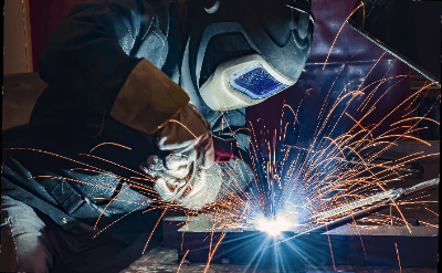
An arc welder is a welding machine that uses arc discharge to join two identical metals.

Arc welding occurs when an electric current flows through non-conductive air by passing a high current between unconnected conductors. The current flow creates an excited state that can reach temperatures of 5,000 to 20,000°C (5,000 to 20,000°F). Since iron melts at around 1,500°C, it is possible to create sufficient temperatures to join iron to iron.

There are several types of arc welders, but basically, an electrode or welding rod is used to join base metals. In this process, inert gas is used to prevent oxidation and nitriding.

Uses of Arc Welders

Arc welders are commonly used for metal structures, including automobiles, railroad cars, ships, aircraft, buildings, construction machinery, and industrial machinery. The base metal is often steel, but it can also join non-ferrous metals such as aluminum and titanium.

Welding is performed in an atmosphere with high nitrogen and oxygen levels, so nitriding and oxidation can cause welding defects. To avoid this phenomenon, inert gas that shuts off nitrogen and oxygen is used during arc welding. The inert gas is shielding gas, and argon or carbon dioxide gas is used.

Principles of Arc Welders

Arc welders are broadly classified into consumable-electrode arc welders and non-consumable-electrode arc welders, depending on whether the electrode for discharge is molten. The consumable electrode type includes shielded arc welding and MIG/MAG welding, while the non-consumable electrode type includes TIG welding and plasma welding.

  1. Shielded Arc Welding Method

This method uses a welding rod with a metal core wire covered with a coating material consisting mainly of calcium carbonate and cellulose to generate an arc discharge. Depending on the power source, AC and DC types are available. The coating material decomposes due to heat, generating shielding gas. This gas protects the welder from oxygen and nitrogen in the atmosphere and prevents welding defects. 

  1. MIG and MAG Welding Methods

MIG/MAG stands for “Metal Inert Gas, Metal Active Gas,” a welding method that uses inert carbon dioxide or argon gas as the shielding gas to prevent oxidation and nitriding.

Welding wire is automatically supplied, resulting in high efficiency. However, it is difficult to weld non-ferrous metals such as aluminum and has the disadvantage that it cannot be used for welding other than ferrous metals.

  1. TIG Welding Method

TIG stands for “Tungsten Inert Gas” and uses tungsten as the electrode for discharge. Argon gas or helium gas is used as the shielding gas. A welding rod must be prepared separately. 

  1. Plasma Welding Method

This method uses tungsten as the electrode for discharge and a plasma arc as the heat source for welding. Plasma has the advantage of extremely high energy density and minimal deformation of the base metal. On the other hand, the welding machine and running costs are high.

Structure of Arc Welders

Arc welders generate an arc discharge by emitting heat electrons from the electrode. The heat energy generated here melts the base metal to make the joint. Standard arc welders can be classified into two welding power sources: alternating and direct currents.

  1. AC Arc Welders

Various types of leakage transformers are used in AC arc welders. Among them, the movable iron core type has excellent characteristics. The primary and secondary coils face each other, and the movable iron core is moved to change the reactance against leakage and adjust the secondary current. 2.

  1. Arc Welders of Direct Current

DC arc welders have an internal mechanism that allows inverter control. Therefore, its internal structure is complicated and has the disadvantages of high prices and poor maintainability. However, they have a wide range of voltage adjustments and can weld at a stable output.

These welding machines are equipped with a welding torch, a device to automatically supply welding rods, and a device to fill and blow out shielding gas.

Other information on Arc Welders

Points to Keep in Mind When Using Arc Welders

The following points should be considered when using commonly used shielded arc welders.

1. Clothing

Clothing should be checked in preparation for welding. Typical clothing includes a work cap or hood, safety glasses, arm covers, leather gloves, a light-shielding protective mask for welding, a front cover, foot covers, and a dust mask.

2. Preparation of Parts

Prepare parts to be used for welding. Welding requires the welder, cabtyre cables, ground clips, welding rod clips, welding rod cable extension joints, power supply tools, and welding rod dryers.

The power tools, etc., should be prepared according to the connection method of the welder and the power source to be connected to. Suppose the connection of the welding machine includes work on a charging circuit. In that case, the Occupational Safety and Health Law requires that the operator receive special training for low-voltage electricity handlers. After the preparation of parts is complete, the tools used for welding are prepared.

Commonly used tools include a Kellen hammer, chipping hammer, wire brush, solid marker, welding gauge, disc grinder, and fire extinguisher. The Occupational Health and Safety Law applies when performing arc welding. It is important to note that it is mandatory to appoint a work supervisor and conduct special health checkups and working environment measurements.

カテゴリー
category_usa

Annealing Furnace

What Is an Annealing Furnace?

Annealing Furnace

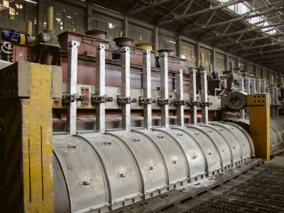
An annealing furnace is a large heating device for applying an annealing process. It can heat various materials such as metals, semiconductors, and glass to high temperatures. Annealing is a technology that corrects distortions in or increases the stability of an object by heating it. This process is used in various materials, such as plastics and metals, to increase crystallization or uniform hardness, respectively. An annealing furnace is widely used for annealing a variety of materials for industrial and research applications.

Uses of Annealing Furnaces

Because many materials require annealing, annealing furnaces are used in various locations.

  • Processing of crystalline plastics: By heating crystalline plastics, the degree of crystallinity can be increased, and stability can be improved.
  • Moisture Removal from Plastics: Plastics absorb moisture, even from the air, and expand. Therefore, plastics are heated in annealing furnaces to remove moisture and correct their size and dimensions.
  • Treatment of Metals: By heating metals, hardness can be made uniform, and stability can be improved.

Principles of Annealing Furnaces

Annealing furnaces use various heating methods, including hot-air and infrared. We focus here on high-performance far-infrared annealing furnaces. These furnaces heat using the ‘radiation’ property of far-infrared rays, differing from standard methods that require direct contact with the heat source.

Far-infrared annealing furnaces are annealing furnaces that heat using the radiation property of far-infrared radiation. Far-infrared radiation is an electromagnetic wave with a longer wavelength than visible light. Irradiating an object with far-infrared rays causes the molecules that make up the object to vibrate and generate heat energy. Since this thermal energy warms the object, non-contact heating is possible. In addition, high temperatures can be created in a short time. Furthermore, the heating temperature varies depending on the wavelength of the far-infrared radiation, making it excellent in that it can be used in different ways depending on the object to be heated.

カテゴリー
category_usa

Alnico Magnet

What Is an Alnico Magnet?

An alnico magnet is a magnet made of aluminum, nickel, and cobalt.

Copper and other elements are sometimes added as additives, and they are used as strong permanent magnets. Due to supply concerns over raw materials, alnico magnets are not as common as ferrite magnets, and their disadvantage is that they are easily demagnetized.

Because of its high Curie temperature, it is resistant to high temperatures and cracking, and has excellent mechanical strength. Alnico magnets are manufactured by casting and sintering.

Uses of Alnico Magnets

Alnico magnets have a high Curie temperature (Curie point 850°C), which means that their magnetic properties do not change significantly with temperature, and they can be used at high temperatures. Due to their excellent mechanical properties, such as resistance to cracking, Alnico magnets are used in various meters, instruments, watt-hour meters, and crime prevention equipment.

In other cases, Alnico magnets in the shape of a 5 cm bar are swallowed by cows to adsorb a bundle of wires and other iron pieces in the third stomach to prevent wound pericarditis.

Properties of Alnico Magnets

Alnico magnets come in three shapes:

  • Bar type
    Round bar type with a small outer diameter of 3 mmφ, indicated by outer diameter × length
  • Ring type
    Shown by outer diameter x inner diameter x height
  • Square shape
    Width x Height x Length

Alnico magnets are characterized by a magnetic force as strong as that of rare earth magnets, such as neodymium magnets. In addition, due to its high Curie temperature, Alnico magnets can be used at high temperatures with little change in magnetism due to temperature. It can also be manufactured in dimensions according to the intended use.

However, its disadvantages include fluctuating costs due to unstable prices of cobalt and nickel, the main raw materials, and its tendency to demagnetize. Since the coercive force is not that great, it may be demagnetized by external magnetic fields or mechanical shocks.

In addition, self-demagnetization often occurs in thin plate shapes with large antimagnetic fields. To compensate for the coercive force, the length in the direction of magnetization must be increased.

Other Information on Alnico Magnets

1. Invention of the Alnico Magnet

In 1931, Tokushichi Mishima invented MK steel, which is mainly composed of iron, nickel, and aluminum alloys. This MK steel was the beginning of a larger trend to utilize alloys for magnetic materials.

Later, Tokushichi Mishima sought to improve the magnetic properties of MK steel by adding cobalt and copper, and this is the foundation of the Alnico Magnet. 1934, Kotaro Honda, Kazumasa Masumoto, Yuki Shirakawa, and others added titanium to MK steel to develop NKS steel with high holding power.

In 1938, GE Corporation of the U.S. announced the Alnico Magnet, which was made by adding copper to NKS steel and became widely used. The composition of the Alnico magnet at this time was 8wt% aluminum, 14wt% nickel, 24wt% cobalt, 3wt% copper, and the rest iron.

2. Degradation of Alnico Magnets

The magnetic force of an alnico magnet decreases with age, temperature, and external magnetic field. Compared to other permanent magnets such as neodymium magnets and samarium-cobalt magnets, Alnico magnets have a lower coercive force, so they tend to lose their magnetic force as time passes since their manufacture.

If Alnico magnets are to be used for a long period, it is necessary to check periodically to see if the magnetic force has decreased. In addition, Alnico magnets have a high Curie temperature and are resistant to heat, but their magnetic force weakens at high temperatures. If the temperature is too high, the magnetism may not recover upon cooling, so it must be used within the proper temperature.

Alnico magnets are strongly affected by external magnetic fields due to their low coercive force. Therefore, in the presence of a strong magnetic field, they cannot retain their magnetic force, leading to a decrease in magnetic force. Another disadvantage is that partial damage, such as rust or deformation, makes it impossible to maintain the magnetism of the entire magnet.

カテゴリー
category_usa

Ion Implanter

What is an Ion Implanter?

Ion Implanters

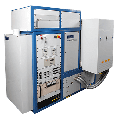
An ion implanter is a sophisticated device used to modify the properties of materials by embedding ionized atoms into them. This technology is crucial in semiconductor manufacturing, enabling the alteration of electrical properties in materials like single-crystal silicon wafers, transforming them from insulators to conductors of electricity.

Applications of Ion Implanters

Ion implanters play a pivotal role in semiconductor production, particularly in the impurity implantation process. They introduce ions into silicon wafers to create areas with specific electrical characteristics, forming n-type or p-type semiconductors through a process known as doping. N-type semiconductors are made using electron-rich element ions, while p-type semiconductors utilize hole-rich element ions.

Principle of Ion Implanters

The core components of an ion implanter include an ion source, analyzer, accelerator, and wafer stage, among others. Ions generated from elements like phosphorus or boron are transformed into a plasma state, then precisely accelerated and shaped into an ion beam. This beam scans across the silicon wafer, implanting ions to alter the wafer’s electrical properties. Heating the wafer during implantation helps reduce crystal defects and enhance the material’s quality through self-annealing.

How to Select an Ion Implanter

Selecting an ion implanter involves considering several factors, including the type and concentration of ions required, the kinetic energy of the implantation process, and the size and type of wafer. High-current, high-energy implanters are necessary for certain applications, and devices capable of heating wafers are required for power device wafers like SiC. Cost, throughput, and the specific requirements of the implantation process are critical considerations in the selection process.

カテゴリー
category_usa

Inserter

What Is an Inserter?

An inserter is a device that automates the process of folding, sealing, and enclosing documents such as invoices and delivery slips. It is also commonly referred to as an encapsulating and sealing machine. Introducing this equipment can reduce costs by shortening working hours and preventing incorrect sealing. In recent years, this equipment has also been used to seal credit card statements to avoid leaking personal information. Specifically, the inserter automatically manages the credit card statement and the envelope to which it is addressed by using a bar code to prevent incorrectly sealed or incorrectly shipped envelopes.

Uses of Inserters

Inserters are devices that mechanize tasks that were previously performed manually.

For example, two tasks are required when direct mail is handled manually: folding the promotional literature and sealing the package.

By using inserters, this work can be automated. 

As a result, the work time can be shortened, and folding errors can be prevented.

Recently, inserters’ functions have evolved to the point where it is possible to seal multiple different printed materials in a single envelope. Barcode control of the envelope and its contents can prevent incorrect sealing and shipping.

Principles of Inserters

Inserters have three parts: the central unit, the operation unit, and the control unit.

The central unit has the following three essential functions:

  1. Folding function to fold documents
  2. Sealing function, which inserts folded documents into envelopes
  3. Gluing function to close the envelope with glue

The control panel used to be an LED panel with only a text display, but more and more products recently have an LCD touch panel.

The actual operation is a screen transition in which the operation to be performed by the user is displayed as an icon for each step. The operation is confirmed by touching it by hand.

The control section controls the operation of the entire inserter. The control unit operates the central unit of the device according to the instructions of the control unit determined by the user, thereby outputting the final deliverables.

The following is a rough guide to the performance of the inserters.

It takes about 7 hours to manually fold 1,000 documents, seal them in envelopes, and glue them together.

If inserters with general essential functions are used, the same process can be completed in about 20 minutes.

In other words, the time required for manual operation can be reduced to about 1/20 of the time needed.

This can contribute to a dramatic improvement in work efficiency and a reduction in work costs.

カテゴリー
category_usa

Blown Film Machinery

What Is a Blown Film Machinery?

Inflation molding is a type of extrusion molding that specializes in bag-shaped films.

The extrusion mold has a ring-shaped opening through which the molten resin is extruded into a thin film. While extruding, cooling air is blown in to expand the film to a specific size and form it into a bag.

Not only single-layer films but also multi-layer films can be formed at the same time.

Uses of Blown Film Machinery

The machine produces films such as food wrap film and plastic bags.

It is also used to form multi-layer olefin films to produce films used in agricultural greenhouses, rice bags, fertilizer bags, general coating films, and food packaging films.

Highly functional films can be molded by adding additives such as pigments, antistatic agents, and AB agents that prevent films and products from sticking together to polyolefin materials such as polyethylene (PE) as well as polyvinyl chloride resin (PVC).

Principles of Blown Film Machinery

The general configuration of an inflation molding machine is as follows.

First, there is an “extruder” that extrudes molten resin, a “round die” which is a mold with an opening of the shape (cylindrical) to be molded, an “inflation and cooling section” that inflates the extruded, film-like resin with air and cools the inflated resin by air to make it solid, a “clamping roll” that tightens the air inside the film. In contrast, the film is then rolled up, cut to the required length with a cutter, etc., and one side is thermally welded to form a pouch.

While inflation has the advantages of a simple structure, low tooling cost, low unit cost due to continuous molding, and the ability to produce thin-walled molded products, it has the disadvantages of not being able to produce thick-walled products and not being suitable for small-lot production.

In addition, it should be noted that products molded with inflation molding machines may have uneven thicknesses and surface defects such as streaks.

カテゴリー
category_usa

Worm Gear Speed Reducer

What Is a Worm Gear Speed Reducer?

Worm Gear Speed Reducers

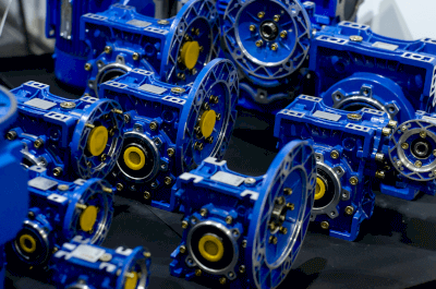
A worm gear speed reducer is a device that utilizes a worm gear as its reduction mechanism.

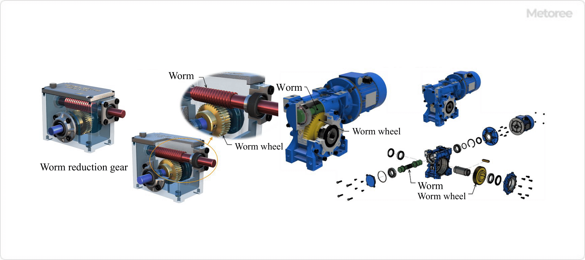
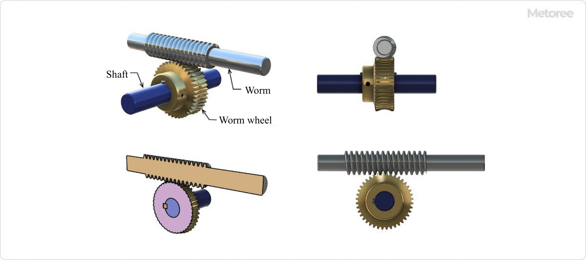
A speed reducer is a device that takes the rotational output of an electric motor or another rotary power-generating device as its input and reduces its rotational speed while increasing its torque. The reduction mechanism comprises various types of gears. One of these gear types is the worm gear, which is a combination of a worm (worm shaft) and a worm wheel.

Other types of reduction gears include spur gear reduction gears, which are commonly used, bevel gear reduction gears, and miter gear reduction gears that consist of bevel gears with orthogonal gear shafts, and planetary gear reduction gears that combine three types of spur gears (sun gears, planetary gears, and internal gears).

Refer to Figure 1 below for the structure of a Worm Gear Speed Reducer.

Figure 1. Structure of worm reduction gear

Figure 1. Structure of worm reduction gear

Applications of Worm Gear Speed Reducers

Worm gear speed reducers, like other reduction gears, are capable of moving large objects with minimal force. As a result, they are commonly used in factory equipment and machinery for power transmission.

Specific Applications of Worm Gear Speed Reducers include:

  • Driving equipment for presses and rolling mills
  • Elevator and escalator driving equipment for medium- and low-speed elevators and escalators
  • Drive equipment for conveyors

Worm gear speed reducers find use across various industries and applications, particularly in the following situations:

  • When Noise Reduction Is Required:
    Worm gear speed reducers are employed in noise-sensitive environments due to their inherently low noise levels.
  • When Quick Stopping Is Necessary:
    Elevators and lifts that require precise and immediate stopping action utilize the self-locking mechanism of worm gear speed reducers.
  • When Dealing with Impact Loads:
    Worm gears, made of soft materials with low hardness such as copper alloys, can absorb shock, making them suitable for applications like rock crushers.
  • When Space Is Limited:
    Worm gears are used in conveyors, packaging equipment, and other machines that require high torque and can be installed in a space-efficient manner.

Principles of Worm Gear Speed Reducer

Figure 2. Principle of worm gear

Figure 2. Principle of worm gear

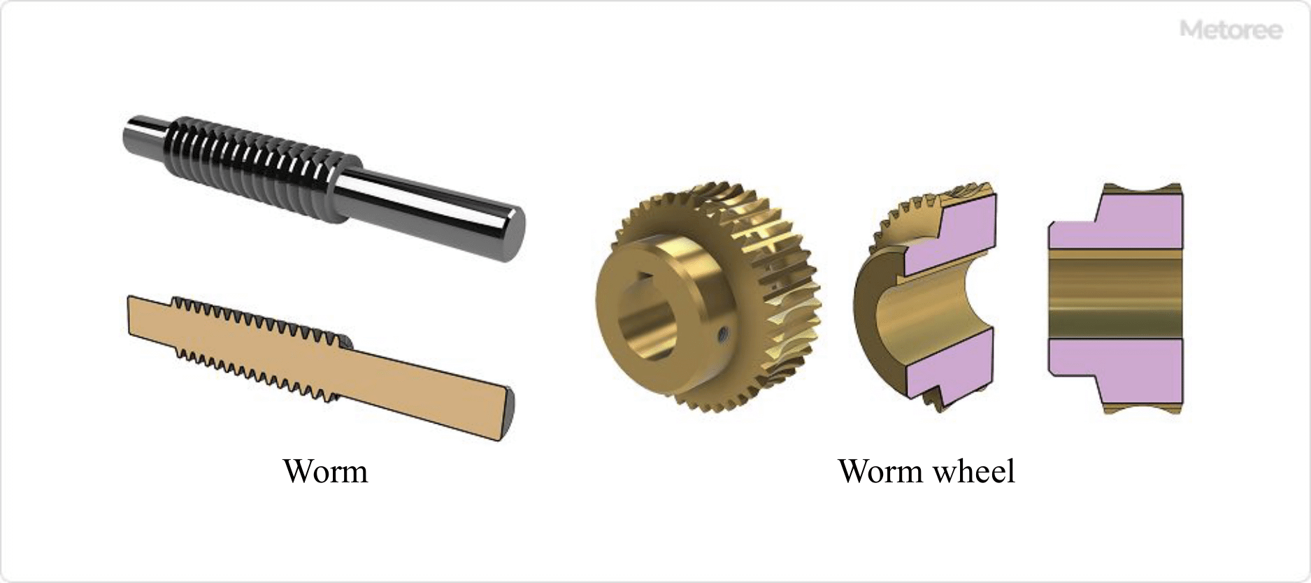
A worm gear speed reducer employs a gear mechanism consisting of a worm (worm shaft or worm axle) and two types of worm wheels.

Figure 3. Worm gear assembly

Figure 3. Worm gear assembly

The worm, a type of screw gear, rotates to push the teeth of the worm wheel, causing it to rotate as if a wedge is being driven into it. When the worm (input side) completes one revolution, the worm wheel (output side) advances by one tooth.

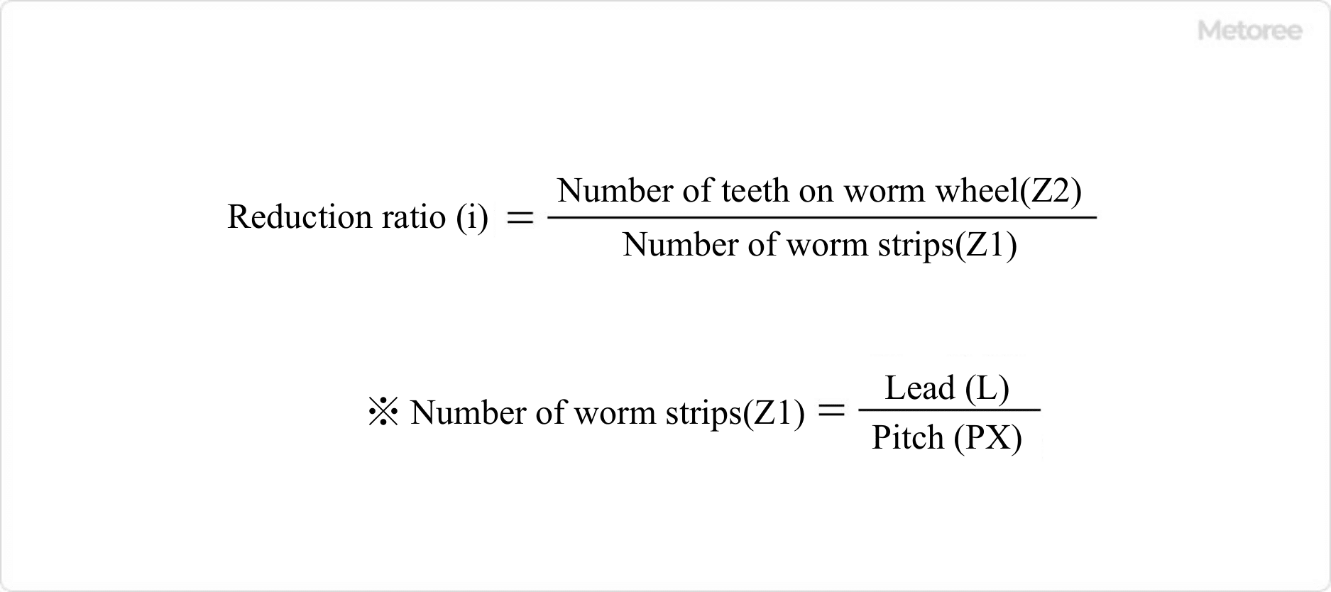
In this context, one set of worm teeth equals one tooth. For example, a worm with two worm teeth means that one rotation of the worm results in a two-tooth rotation of the worm wheel.

The reduction ratio of a worm gear can be calculated as follows:

Figure 4. Reduction ratio of worm gear

Figure 4. Reduction ratio of worm gear

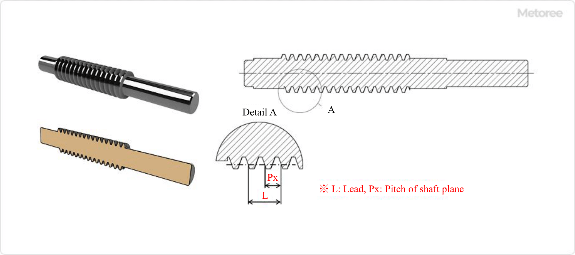
Refer to Figure 5 below for worm dimensions.

Figure 5. Worm dimensions

Figure 5. Worm dimensions

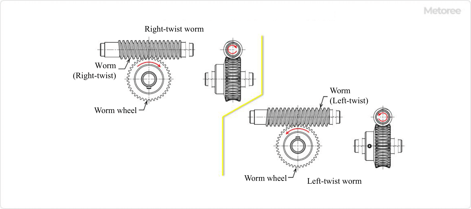
The worm gear can rotate in both directions (clockwise and counterclockwise when viewed from the input shaft side). This direction can be determined by selecting the right-hand or left-hand twist direction for the worm. The same rotation of the worm will result in the opposite rotation direction of the worm wheel. Refer to Figure 6 below for the worm twist direction and worm wheel rotation direction.

Figure 6. Direction of worm twist and worm wheel rotation

Figure 6. Direction of worm twist and worm wheel rotation

Features of Worm Gear Speed Reducer

A worm gear speed reducer possesses six significant features:

1. High Reduction Ratio

Single-stage gears (comprising one worm and one worm wheel) can achieve high reduction ratios, reaching 1/60 or even 1/120 for specialized gears.

2. Orthogonal Rotating Shafts

The input and output shafts are orthogonal to each other, meaning they lack a coaxial direction.

3. Arbitrary Rotation Direction

The direction of rotation for the output shaft, connected to the worm wheel, can be altered by selecting either the left or right worm twist direction.

4. Freedom of Shaft Arrangement

Input and output shafts can be installed in four directions on one or both sides.

5. Self-Locking Effect

The worm side (input shaft side) can rotate the worm wheel side (output shaft side), but the reverse is not true, thanks to the self-locking effect.

6. Low Vibration and Low Noise

The meshing of the worm and worm wheel provides greater slippage due to linear contact, resulting in lower noise and vibration compared to spur gears, bevel gears, or other rolling transmissions.

One drawback of worm gear speed reducers is their large contact surface on the meshing tooth flanks, which can lead to seizing. To mitigate this, the worm is typically made of alloy steel or other hard materials that undergo heat treatment, while the worm wheel is crafted from copper alloy, cast iron, or other low-hardness materials to reduce friction.