カテゴリー
category_usa

Power Over Ethernet (PoE) Extender

What Is a Power Over Ethernet (PoE) Extender?

Power Over Ethernet (POE) Extenders

Power over Ethernet (PoE) is a technology that simultaneously provides data communication and power supply through an ethernet cable.

This enables both data communication and power supply to be realized with a single cable, instead of the conventional method of separating data communication and power supply, thereby simplifying infrastructure facilities and reducing costs. PoE is used in a wide variety of devices, including surveillance cameras, wireless LAN access points, and VoIP telephones.

Uses of Power Over Ethernet (PoE) Extenders

A typical use for power over ethernet (PoE) extender is in IP-based surveillance camera systems. Since power and data communication are carried over a single cable, it does not matter if there is no power supply at the location where the camera is installed.

This makes it easy to extend the range of surveillance and contributes to enhanced security. Other applications include the following

1. Wireless Network Equipment

Wireless LAN access points are another important use case for PoE. When providing wireless connectivity throughout a building, PoE allows for flexible device placement. Access points can be installed in optimal locations, without being limited by where power supply is required.

2. VoIP Telephony

The same cable is used for telephone and data transmission, making it easy to install and move the phone. In addition, phones can be used even during power outages, making them an excellent means of communication during emergencies.

3. IoT Devices

PoE is used to power IoT devices, especially sensors and actuators used in smart buildings and smart homes. This allows power supply and data communication over a single cable, greatly simplifying installation and management.

4. Network Switch

Using a PoE-enabled network switch increases the number of devices that can be powered through the switch. This makes cable management easier and enables more efficient network construction.

Principle of Power Over Ethernet (PoE) Extenders

Ethernet cables are typically bundles of eight copper wires, which are responsible for data transmission and power supply.

In this case, there are two modes of supplying power in PoE: Alternative A and Alternative B.

1. Alternative A

In Alternative A, data communication and power are provided using the same pair of cables (1,2 pair or 3,6 pairs). This is also referred to as “end span”.

2. Alternative B

Alternative B uses cables with different pairs for power supply and data communication (4,5 pairs and 7,8 pairs are used for power supply). This is also called the “midspan” or “injector” method.

3. PSE and PD

There are two main components in a PoE system: PSE (Power Sourcing Equipment) and PD (Powered Device). PSE is the device that provides power (such as a network switch or injector) and PD is the device that receives power (such as IP cameras, wireless LAN access points, etc.).

PSE detects whether a PoE-enabled device is connected and provides the appropriate power. This provides safe protection against non-PoE devices being accidentally connected. It also can accurately measure the amount of power required by the PD and supply it without over- or under-delivery.

Types of Power Over Ethernet (POE) Extenders

There are several different standards for power over ethernet (PoE) extenders, each supporting different power levels; the differences between PoE, PoE+, and PoE++ are as follows:

1. PoE (IEEE 802.3af)

This is the first PoE standard and can provide up to 15.4 watts of power. It is suitable for low-power devices such as IP cameras, VoIP phones, and some wireless access points.

2. PoE+ (IEEE 802.3at)

This standard is an enhanced version of PoE with the ability to provide up to 30 watts of power. This makes it suitable for high-power devices, such as panoramic IP cameras, and high-performance wireless access points like Wi-Fi 6.

3. PoE++ (IEEE 802.3bt)

This standard has been further enhanced and can provide up to 60 watts (Type 3) or 99 watts (Type 4) of power. This allows for the most power-hungry devices that need to be powered over power over ethernet (POE) extender. Examples include digital signage, high-performance Wi-Fi access points, and some laptops.

カテゴリー
category_usa

Tap Holder

What Is a Tap Holder?

A tap holder is a specialized tool used for cutting internal threads in materials such as metal. It securely holds a tap during machining operations, facilitating precise threading. Tap holders are commonly used in manual threading tasks and are essential for ensuring high-precision and efficient work. They are manually operated, requiring no power supply, making them suitable for small-scale repair work in various locations.

However, using a tap holder requires precision in terms of pressure and rotational speed control. Incorrect operation can negatively affect threading quality.

Uses of Tap Holders

Tap holders are versatile tools used in various industries and applications.

1. Machining

In metal processing, tap holders are essential for accurately cutting threaded holes in machine parts and assemblies. They provide consistent and precise threading, crucial for part assembly and installation.

2. Woodworking

Tap holders are also used in woodworking, particularly for accurately cutting screw holes in furniture making and wooden product manufacturing. They ensure secure screw attachment and provide a durable finish.

3. Automobiles

In automotive repair, tap holders are employed to repair damaged screw holes, especially in engine parts. They facilitate the accurate recreation of threaded holes for part installation.

Principles of Tap Holders

Tap holders are designed to securely hold the tap, transmit torque, maintain straightness during tapping, and absorb thread pitch errors. They often have a square shaft to prevent slippage and must be dimensioned according to the tap diameter. Rigidity is crucial to maintain straightness under machining loads. Some tap holders feature telescopic mechanisms to absorb errors in travel distance during threading.

Types of Tap Holders

There are mainly two types of tap holders: hand taps and tap holders for processing machines.

1. Hand Taps

Hand tap holders are manually operated with a handle, requiring skillful control of force and angle for accurate threading.

2. Tap Holders for Processing Machines

These tap holders are attached to the rotary spindle of machine tools, streamlining threading operations in mechanized environments. They enable automated precision threading for mass production and high-precision machining.
カテゴリー
category_usa

Cam Clutch

What Is a Cam Clutch?

Cam Clutches

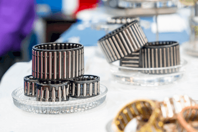
A cam clutch is a one-way clutch that transmits torque in only one direction. It is also called a cam-type one-way clutch or roller-type one-way clutch.

One of the characteristics of a one-way clutch is that it can only rotate in one direction, like a bicycle pedal. A cam clutch has the same characteristic. When a rotational torque opposite to the torque in the specified direction is applied, the clutch does not engage internally, causing it to spin out of alignment.

Cam clutch is widely used in automobiles, helicopters, conveyors, and other industrial machinery.

Uses of Cam Clutches

As a type of one-way clutch, it is mainly used when torque is transmitted in only one direction. Taking advantage of its idling property when reverse rotational torque is transmitted is sometimes used as a component to prevent reverse rotation and blurring of the drive components.

It may also be used as a clutch for two-speed drives by using the properties of spinning and meshing differently. By connecting gears and other drive components to a shaft, mounting two cam clutches on each end of the shaft, and connecting different drive motors with varying speeds to the cam clutches, it is possible to use two various drive sources by having one motor spinning and the other spinning.

Combining drive components makes it possible to combine the torques of two drive motors to create a dual drive.

Principles of Cam Clutches

Cam clutches have an outer and inner ring, with a cam and spring built between them. The cams are laid regularly between the outer and inner rings, like balls in a ball bearing.

What differentiates cams from ball-bearing balls is their shape. Instead of a regular circle, they have a particular oval shape. The lower half is a traditional circle, and the upper half is a triangle with two sides. This is done to prevent the cam from tipping over inside the clutch.

When torque is applied to the cam clutches in the direction of engagement, the cam acts as a bar between the outer and inner rings, thereby engaging the outer and inner rings and applying rotational torque in the same direction.


A groove is cut in the cam for spring, and the spring is installed to cover the entire cam. This spring tightens the cam so that the cam can easily tilt in the direction of engagement. The outer and inner rings do not engage when reverse rotational torque is transmitted because this spring pulls the cam in the direction of engagement. The cam, tilted toward engagement by the spring, slides out of engagement when reverse rotary torque is applied, releasing the torque.

カテゴリー
category_usa

Sheet Metal Bracket

What Is a Sheet Metal Bracket?

Sheet Metal Brackets

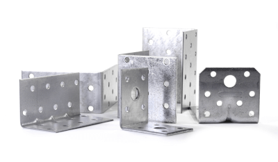
A bracket is a support or mounting bracket used to secure machine parts. Brackets that are manufactured through sheet metal processing are referred to as sheet metal brackets.

Sheet metal brackets are often processed through bending, drilling, tapping, and either C-chamfering or R-machining to prevent injuries.

To increase strength and support heavy loads, rib structures are welded onto these brackets, and techniques such as bending and pressing (triangular rib processing) are employed.

For heavy objects, sheet metal materials are typically iron-based, whereas for lighter objects, aluminum-based or other iron-based materials are used.

Uses of Sheet Metal Brackets

Sheet metal brackets are employed to secure mechanical and electrical components that require moderate strength in various equipment types, such as industrial machinery, optical devices, measuring instruments, automobiles, and home appliances.

Beyond merely securing parts, these brackets may also feature mechanisms for adjusting the position of fixed elements, such as utilizing long round holes instead of standard machined holes.

While machined parts are often used for components requiring high strength, sheet metal, being more cost-effective, is also used for securing heavy objects by welding ribbed structures to enhance strength.

Principles of Sheet Metal Brackets

With the advent of low-cost, high-power lasers, the capabilities of laser cutting machines have significantly improved. This advancement has enabled the cutting of thick sheet metal, previously a challenging task, allowing the production of sheet metal brackets up to 9 mm thick at a relatively low cost.

For large-scale production, brackets can be manufactured more cost-effectively using a turret punch press or by fabricating dies for press work.

Even with sheet thicknesses as thin as 1 mm or less, strong taps can be created using a drawing process known as “burring” combined with tapping.

Sheet metal brackets with multiple functionalities can be produced by incorporating welding nuts and spacers, which can be added with relative ease.

Standard sheet metal brackets are bent, but caution is advised as the shape of the bracket may be affected by holes near the bending area that is being stretched.

カテゴリー
category_usa

Static Eliminator

What Is a Static Eliminator?

A static eliminator, also known as an ionizer, is a device that removes static electricity from objects. It is essential in manufacturing processes to prevent equipment malfunctions and product defects. Static eliminators work by generating ions (cations and anions) that neutralize static electricity through ion collision. They are effective on both conductors and insulators and can be installed for continuous static removal.

Uses of Static Eliminators

Static eliminators are versatile and used in various industries for different applications:

1. Chemical Industry

In chemical manufacturing, static eliminators prevent static-related issues during production. They ensure smooth processes by preventing static-charged products from adhering to machinery or combining.

2. Electronic Products

Static eliminators are crucial in protecting electronic circuits from static discharge, which can cause damage or malfunction. They are indispensable in manufacturing displays, IC chips, and semiconductor wafers.

3. Relaxation

For relaxation and stress reduction, static eliminators are used to generate negative ions. These ions are believed to promote serotonin secretion, contributing to relaxation and a pleasant mood.

Principle of Static Eliminators

Static eliminators operate by ion generation. They use various ionization systems to produce positive or negative ions, which interact with air particles, leading to adsorption and neutralization. The type and amount of ions produced vary by the design of the static eliminator. They often include a power supply and control circuitry for effective ion production and emission.

Note: Static eliminators also provide air purification and sterilization benefits, though their specific effects depend on the product’s performance and environmental conditions.

Types of Static Eliminators

There are several types of static eliminators, categorized based on their ion generation methods.

1. Corona Discharge Type

This type uses corona discharge, where the high voltage applied to an electrode needle generates ions to neutralize static electricity. It effectively reduces static electricity on object surfaces but requires high voltage.

2. Radiation Type

Radiation-type eliminators use soft x-rays, alpha rays, beta rays, etc., to generate ions. These ions neutralize static electricity efficiently but require careful handling due to potential radiation hazards.

カテゴリー
category_usa

Ultra-Low Temperature Freezer

What Is an Ultra-Low Temperature Freezer?

Ultra Low Temperature Freezers

An ultra-low temperature freezer is a refrigeration device capable of maintaining temperatures significantly lower than standard refrigerators, typically between -80°C to -196°C. Some models even use liquid helium for temperatures near -268.9°C, the boiling point of liquid helium. These freezers are ideal for materials and samples requiring storage or processing at low temperatures.

Uses of Ultra-Low Temperature Freezers

Ultra-low temperature freezers have diverse applications in medical, food production, and manufacturing industries.

1. Medical

These freezers are crucial for storing biological samples, pharmaceuticals, and regenerative medicine materials. They are also integral in hospitals for biochemical sample storage and biobank management. Their installation costs are high, but they offer low greenhouse gas emissions.

2. Food Products

Ultra-low temperature freezers are used in frozen food production and preservation, maintaining the quality, freshness, and flavor of a wide range of foods, including vegetables and seafood.

3. Manufacturing Industry

Essential in the semiconductor industry, these freezers are used for cooling processes, material synthesis, and handling superconducting materials.

Principle of Ultra-Low Temperature Freezers

Ultra-low temperature freezers employ advanced cooling techniques such as evaporative cooling with liquid nitrogen or helium and refrigerant circulation using substances like CFCs. Recent models use environmentally friendly refrigerants like R32 and R410A.

How to Select an Ultra-Low Temperature Freezer

Selection factors include capacity, cooling temperature range, and functionality.

1. Capacity

Choose based on the quantity and size of items to be stored, allowing for future demand changes.

2. Cooling Temperature Range

Identify the required cooling temperature range, typically between -80°C and -196°C, though some applications may need lower temperatures.

3. Functionality

Look for features like temperature controls and door locks, tailored to your sample and product management needs.

カテゴリー
category_usa

Single-Axis Positioning Stage

What Is a Single-Axis Positioning Stage?

Single-Axis Positioning Stages

A single-axis positioning stage is a unit that can be positioned in one specific direction.

This type of stage can move only in a single direction, such as horizontally (X-axis), vertically (Z-axis), or in rotation, angle, or goniometric positions, depending on the model.

When using this unit, consider the direction of movement and positioning accuracy based on the application.

As it is a single-axis positioning stage, a 2-axis stage is recommended for movements in both X- and Y-directions.

If a unit equipped with a micrometer or a similar device is used, precision in movements can be achieved.

Uses of Single-Axis Positioning Stages

Single-axis positioning stages are utilized for positioning, adjustment, and other movable adjustments in inspection equipment, devices, and parts requiring precise movements.

These stages vary in accuracy, so it is important to select the ones that best suit the intended purpose and usage conditions.

Examples of single-axis positioning stages include:

  • Positioning equipment for product inspection.
  • Stroke adjustment in equipment positioning (part assembly).
  • Adjustment of product assembly jigs for model changes.
  • Transportation and positioning of FA equipment.

Principles of Single-Axis Positioning Stages

A single-axis stage consists of three main mechanisms: guide, feed, and clamp.

There are three types of guide mechanisms:

  • Dovetail Groove: a mechanism that slides between male and female dovetail grooves.
  • Crossed Rollers: a mechanism in which rollers are arranged on V-groove rails and move across the V-groove.
  • Linear Ball: a mechanism where balls are arranged in grooves and move by sliding within them.

Each feed mechanism also has distinct characteristics:

  • Rack and Pinion: this mechanism is less precise but essential for speed and not suitable for precise positioning.
  • Feed Screw: used for fine adjustments (around 0.5 mm), not ideal for long strokes.
  • Micrometer: ideal for precision adjustments (in 0.01 mm increments), not suitable for long strokes.
カテゴリー
category_usa

Dual-Axis Positioning Stage

What Is a Dual-Axis Positioning Stage?

Dual-Axis Positioning Stages

The equipment configuration generally consists of stages in each axis direction stacked on top of each other. A dual-axis positioning stage (XY-axis stage) has two axes: an X-axis for left/right movement and a Y-axis for vertical movement. The use of this stage has the advantage of facilitating positioning.

The accuracy and features vary depending on the stage guide system and feed mechanism, so selecting a stage that best suits the application is necessary.

Uses of Dual-Axis Positioning Stages

The main applications of 2-axis stages are for manufacturing semiconductor devices and microscopic observation, which require positioning. There are various types of stages with positioning accuracy ranging from low precision to high precision depending on the guide system and feed mechanism, and they have different features.

Principles of Dual-Axis Positioning Stages

Dual-axis positioning stages are composed of a “guide mechanism” and a “feed mechanism. Since the characteristics of each mechanism differ depending on its type, the following is a description of typical kinds of stages.

Guide mechanism

  • Dovetail groove type: A dovetail groove type is a guiding mechanism in which the male and female trapezoidal grooves slide together.
  • Crossed roller system: A system that moves by linear contact between a roller and a V-groove rail, providing high rigidity. It is also suitable for precise positioning due to its low friction and minute feed rate.
  • Ball type: This is a mechanism that moves by contact between an R-groove machined along a circular arc and a ball, which provides good contact between the R-groove and the ball and stable load capacity in all directions. The movement accuracy is not significantly different from the cross-roller system and is also suitable for accurate positioning.

Feed Mechanism

  • Rack and pinion: This feed mechanism combines a rail with cut teeth called a “rack gear,” and a gear called a “pinion”. It is characterized by its ability to move the stage quickly but is unsuitable for high-precision positioning.
  • Feed screw: This is a screw-type feed mechanism that utilizes the relationship between the male and the female thread. It can feed the stage at the resolution of the screw pitch, enabling fine feed, but the feed speed is slow, making it unsuitable for positioning over long strokes.
  • Micrometer: This mechanism can feed stages with finer precision than a feed screw. Its internal structure is almost the same as that of a feed screw, but it is also equipped with a scale to determine the amount of travel accurately. The feed speed is also slow, so it is not suitable for positioning over long strokes.

Select the combination that best suits your application and configure Dual-Axis positioning stages from the above guide and feed mechanism choices.

The operation of Dual-Axis positioning stages is not limited to manual positioning; it may also be used as Dual-Axis positioning stages capable of automatic positioning, with each axis driven by a motor. In this case, since positioning accuracy is determined by the feed mechanism type and the drive motor’s resolution, the selection of motor specifications is also essential.

Generally, servo motors or stepping motors are used when precise positioning is required.

カテゴリー
category_usa

CAE Software

What Is CAE Software?

CAE software is software that uses a personal computer or supercomputer to calculate air flow, heat transfer, and stresses on a structure.

CAE software is often used as an alternative to building and testing in a laboratory or on a structure.

Since experimental facilities and large structures can be difficult to prototype, low-cost CAE software is used.

Uses of CAE Software

CAE software is mainly used in the product development process and is widely used in the manufacturing industry, such as in the automotive industry, where CAE software can be used to build prototypes and evaluate product performance without experimentation.

This has the advantage of shortening development time and reducing prototype costs. CAE software is also used in the aerospace and other fields as an alternative to experiments on large structures or in special environments. For example, when studying airflow around the wings of an airplane, it is necessary to build a reduced-size model and conduct experiments, which are costly and time-consuming.

With CAE software, however, it is possible to obtain wind velocity and pressure distributions on a computer that are more detailed than those obtained from experiments. This more detailed data may be useful in clarifying the causes of defects, making it highly practical.

Principle of CAE Software

CAE software can reproduce various physical phenomena on a computer by solving equations on a PC or workstation. For example, RIKEN’s simulation on splashing droplets is the result of reproducing the phenomenon of splashing droplets.

Simulation begins with the creation of CAD data. Then, after a preparatory stage (pre-processing), such as element partitioning and setting of boundary conditions and physical properties, the simulation begins (post-processing), in which the equations are calculated. After the simulation is complete, the results are visualized and analyzed.

Some software specializes in pre-processing, such as element partitioning, while others specialize in visualizing the results after post-processing. Most CAE software integrates pre-processing and post-processing, while CAE software in general is software that calculates equations, i.e., software that performs only post-processing.

CAE software uses a technique called discretization, in which elements are partitioned so that the equations of the fluid or structure under consideration are easy to solve. In most cases, the equations solved by CAE software are partial differential equations. Since solutions to partial differential equations are often not available, calculations are performed on a computer to obtain approximate solutions. The basic role of CAE software is to find approximate solutions by computer after discretization.

Other Information on CAE Software

1. Discretization of CAE Software

The finite difference method and the finite element method are well-known methods of discretization, which are used to discretize space and structures. For simulating phenomena that vary with time, implicit and explicit methods are used.

CAE software also uses mathematical formulas to determine physical properties that depend on temperature and other factors, and there is a wide variety of methods used in CAE software.

2. CAE Software Simulation Software

CAE Software has a wide variety of simulation software. Typical examples include thermo-fluid analysis software, structural analysis software, and electromagnetic field analysis software.

Thermo-Fluid Analysis Software
Thermo-fluid analysis software is software that can analyze thermal fluid by solving equations that model fluid flow and heat transfer using a computer and expressing them through simulation.

Structural Analysis Software
Structural analysis software is software that uses simulation to analyze physical quantities that change when loads are applied to the analysis target. The finite element method and other methods are often used in structural analysis software.

Electromagnetic Field Analysis Software
Electromagnetic field analysis software is used to investigate the effects of electromagnetic waves and magnetic forces on objects. It is used in a wide range of industries, such as automotive, space, and defense.

カテゴリー
category_usa

CCD Detector

What Is a CCD Detector?

Figure 1. Top view of CCD sensor

Figure 1. Top view of CCD sensor

A CCD detector (Charge-Coupled Device sensor) is a semiconductor device that converts light intensity into electrical charge as a charge-coupled device.

CCD detectors are a type of image sensor (sometimes called CCDs) and were the dominant type until 2004 when they were surpassed by CMOS sensors in terms of the number of shipments.

They consist of a large number of elements called pixels arranged in a grid pattern as shown in Figure 1. The number of pixels in a camera refers to the number of these elements, using the unit of pixels. In practice, the number is usually in the millions of pixels.

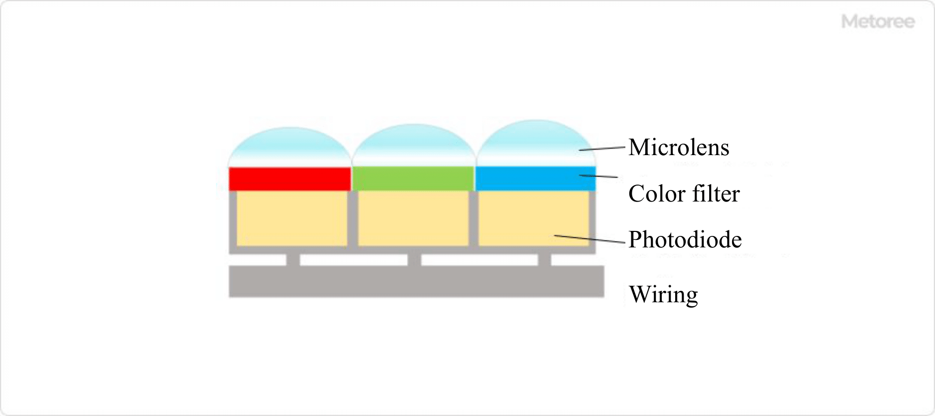
Pixels transmitting the three primary colors of light, red, green, and blue (RGB) or their complementary colors cyan, magenta, yellow, and green (CMYG), are arranged in a mosaic-like pattern, and each pixel is transmitted in turn vertically and horizontally, and the signal is amplified by an amplifier and transmitted as image data. This sequence of operations is often referred to as a bucket relay. In Figure 1, the wiring is shown as if it were next to the pixel, but in reality, the wiring section is located below the pixel. (See Figure 2)

Uses of CCD Detectors

While CMOS sensors are the mainstream in cameras, video cameras, and scanners, CCD detectors are often used in many popular digital cameras, astronomical telescopes, and microscopes because of their superior sensitivity in long exposures.

In recent years, CCD detectors are increasingly being used in the built-in cameras of cell phones. These light detectors are used in many fields, including light intensity measurement, image measurement, DVD pickups, and optical signal detection in optical communications.

Principles of CCD Detectors

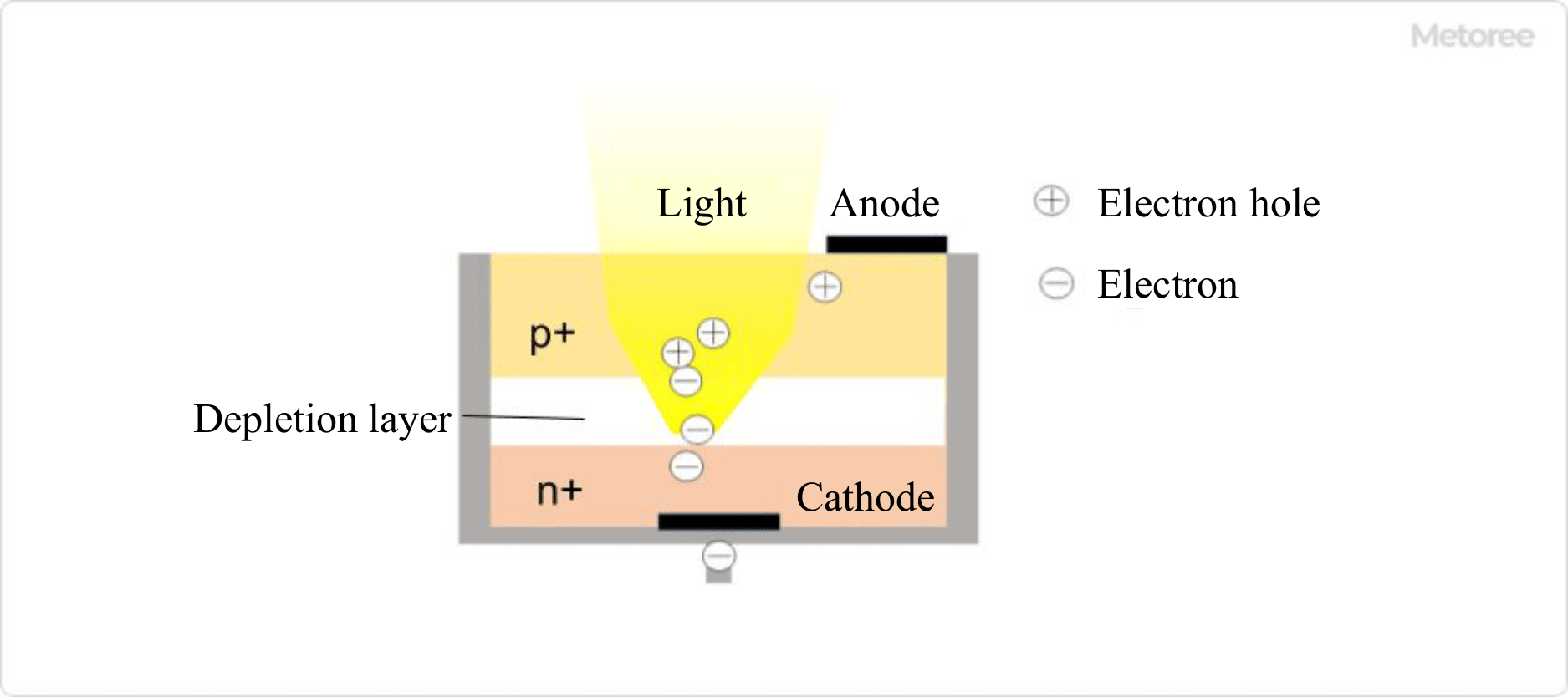
When the depletion layer of a photodiode receives light, an electron-hole pair is formed inside. This is called the photoelectric effect. As the intensity of light increases, the amount of charge stored increases. The phenomenon in which a voltage corresponding to the intensity of light is generated by exposure to light is called the photovoltaic effect.

CCD detector is thus responsible for converting the intensity of light into an electrical signal.

Structure of CCD Detector

As shown in Figure 2, a CCD detector consists of a light-collecting lens on the incident side, a filter that transmits light of a specific wavelength, and a photodiode with layers of p-type, n-type, and i-type semiconductors, mainly made of silicon, sandwiched between metal electrodes (cathode and anode) on the top and bottom.

1. Microlens

Microlenses are placed on the top surface of each pixel to focus light. They are also called on-chip microlenses because they are formed on wafers using glass or resin materials in the same way as semiconductor devices.

2. Color Filter

Figure 2. Conceptual diagram of CCD sensor pixel cross-sectional view

Figure 2. Conceptual diagram of CCD sensor pixel cross-sectional view

Color filters are formed on thin glass substrates with a color resist film that selectively transmits light in a specific wavelength range, allowing red (R, 640~770nm), green (G, 490~550nm) and blue (B, 430~490nm) light to enter the photodiode directly below. The light is then incident on the photodiode directly below it. A thin black partition called a black matrix is formed between the color filters to prevent the colors from mixing with each other. Because they are made on a semiconductor wafer in the same manufacturing process as semiconductors, they are also called on-chip color filters.

3. Photodiode

Figure 3. Conceptual diagram of photodiode structure and operation

Figure 3. Conceptual diagram of photodiode structure and operation

A photodiode consists of a p-type semiconductor on the top (light-entering side) and an n-type semiconductor on the bottom, with an anode on the top and a cathode on the bottom.