カテゴリー
category_usa

Expansion Joint

What Is an Expansion Joint?

An expansion joint is a specialized pipe fitting designed to accommodate changes in the length of pipes.

These pipe fittings are essential components that connect, redirect, and branch pipes in a piping system. They play a crucial role in absorbing the expansion and contraction of pipes caused by temperature fluctuations, earthquakes, and other factors. Expansion joints enable pipes to expand and contract as needed, helping to maintain the integrity of the piping system.

In addition to handling changes in pipe length, expansion joints are capable of absorbing vibrations and shocks. This feature contributes to reducing noise and vibrations within piping systems and mechanical equipment, enhancing equipment stability and overall comfort.

However, it’s important to note that expansion joints require regular maintenance. Depending on their usage and environmental conditions, the clamps and fasteners of expansion joints may need to be periodically tightened, and worn components may need replacement. Neglecting maintenance can result in decreased joint performance and an increased risk of leaks and failures.

Uses of Expansion Joints

Expansion joints are used in various applications, including the following:

1. Heaters and Cooling Systems

Expansion joints are used in heat exchange equipment such as heaters and cooling systems. When the length of piping changes due to thermal expansion or vibration, expansion joints can absorb the change and reduce the stress on the piping. This improves the efficiency and safety of heat exchange equipment and extends the life of the facility.

2. Gas Pipelines

Expansion joints are often used in gas pipelines. Expansion joints accommodate changes in gas pipeline expansion and displacement caused by earthquakes and ground movement. They ensure pipeline safety and improve the efficiency of the supply system.

3. Ships

Expansion joints are also used in the construction of ships and offshore facilities. Expansion joints are often incorporated into pipelines to accommodate displacement and deformation caused by vibration and waves at sea. They ensure the mobility and durability of ships and facilities and improve adaptability to environmental changes.

4. Automobiles

Expansion joints are often used in exhaust systems, such as automobiles, to efficiently discharge exhaust gases from the engine. When the length of the exhaust pipe changes due to engine vibration or temperature changes, expansion joints absorb the changes.

This prevents pipe damage and leakage due to high temperatures and vibration, thereby improving the efficiency and reliability of the exhaust system.

Principle of Expansion Joints

The principle of expansion joints is based on elastic materials and design. Elastic and flexible materials are often made of rubber or plastic. This allows the pipe to accommodate changes in length.

Several convolutions or ribs are arranged inside the expansion joint. These convolutions and ribs are the parts that deform and provide flexibility as the joint expands and contracts.

Expansion joints are attached to the ends of two pipes or tubes to be connected. One end has internal ribs or convolutions, while the other end has external ribs or convolutions.

Types of Expansion Joints

There are three typical types of expansion joints: sleeve type, bellows type, and vented type.

1. Sleeve Type

This is a fitting with an internal sleeve. The sleeve can be slid into the pipe at one end using a slip joint and fitted into the pipe at the other end. The sleeve is highly elastic and can be adjusted according to the amount of expansion or contraction.

2. Bellows Type

Bellows-type joints are fittings with bellows. Since it is completely sealed, there is little risk of leakage. However, there is a possibility of fatigue failure due to repeated expansion and contraction.

For effective operation, a fixing point must be provided at both ends, which limits the installation location. In addition, the fixed points are subject to spring reaction force due to bellows displacement and static thrust due to internal pressure, so they must have adequate strength.

3. Bent Type

This type of joint has a bendable portion (bent). The bendable portion can be U-shaped, Ω-shaped, or loop-shaped, and absorbs expansion, contraction, deflection, and torsion of the piping.

Because of its simple structure, it is characterized by high durability. However, it requires a large space for installation.

カテゴリー
category_usa

Transient Voltage Surge Suppressor

What Is a Transient Voltage Surge Suppressor?

A transient voltage surge suppressor (TVSS), commonly referred to as a TVS diode, is designed to protect electronic devices and components from overvoltage surges and electrostatic discharge (ESD) noise. It utilizes the reverse breakdown voltage characteristic of the Zener diode’s PN junction to stabilize transient voltages.

TVS diodes are favored for their excellent frequency response, offering protection against short pulse width transient voltage surges and ESD noise, which ordinary Zener diodes fail to guard against. However, they are not recommended for long pulse width surges, such as those caused by lightning. For optimal protection, they should be connected in parallel with the devices at risk of electrical overstress.

Applications of Transient Voltage Surge Suppressors

TVS diodes are utilized across a broad spectrum of applications to shield sensitive electronic equipment, data lines, and other critical devices from electrical transients. They ensure a steady output voltage in the presence of transient voltages, within the protected device’s rated voltage. Common uses include automotive and consumer electronics, where they safeguard against surge voltages within the equipment. Due to their superior frequency characteristics, TVS diodes are frequently employed in communication signal circuits.

To maximize effectiveness, TVS diodes are installed between the signal line and ground (GND) near the entry point of external noise, typically close to the board connectors where transient voltages and ESD noise usually infiltrate via the harness.

Principle of Transient Voltage Surge Suppressors

Although TVS diodes vary in design and characteristics, their primary function is to provide consistent overvoltage protection. They achieve this through high energy absorption capability, safeguarding electrical circuits from transient surges. Upon encountering an overvoltage that exceeds the diode’s reverse breakdown voltage, the TVS diode conducts current, leveraging the Zener diode’s properties to maintain voltage within safe limits, thus preventing circuit damage.

Response times differ among TVS diodes, typically around 1ps for TVS diodes and less than 1us for avalanche diodes, enabling quicker reaction to overvoltages than other components like varistors, without performance degradation over time or use.

How to Select a Transient Voltage Surge Suppressor

1. Allowable Voltage

The selected TVS diode’s allowable voltage must exceed the maximum voltage of the circuit it protects, as TVS diodes are not intended for constant current carrying.

2. Capacitance

Due to their inherent capacitive nature, TVS diodes can affect the signal’s rise and fall times by acting like capacitors under normal conditions. It’s crucial to choose a diode with a capacitance compatible with the signal specifications to preserve signal integrity.

3. Clamp Voltage

The clamp voltage should be below the maximum rated voltage of the protected device. However, the effective clamping voltage may be higher than datasheet values due to board patterns and other factors, necessitating a selection margin for clamp voltage.

カテゴリー
category_usa

Spiral Reamer

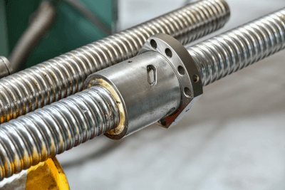
What Is a Spiral Reamer?

A spiral reamer is a specialized cutting tool designed for drilling applications. It consists of a conical body and a spiral blade. The spiral blade cuts diagonally against the hole’s wall as it rotates, making spiral reamers ideal for adjusting hole diameters with precision. During cutting, chips are efficiently removed, and the spiral design ensures precise cutting while maintaining a consistent hole diameter. Spiral reamers are commonly operated manually but can also be used with CNC machines.

Uses of Spiral Reamers

Spiral reamers find diverse applications in various industries. Here are some typical uses:

  • Drilling: Used for drilling holes in automotive engine parts, aircraft frames, and more.
  • High-Precision Drilling: Employed in the manufacture of precision machine parts and medical equipment.
  • Groove Cutting: Used for machining grooves in gears, bearings, and other components.
  • Cutting Various Materials: Suitable for machining metals, plastics, wood, and other materials.
  • Machining Long Holes: Applied in the drilling of long holes in automobile frames and ship structural parts.

Principle of Spiral Reamers

The process of enlarging a hole using a spiral reamer involves several steps:

1. Insertion of Spiral Reamer

The spiral reamer’s shank is attached to a tool such as a handle or drill chuck, and the cutting edge is accurately aligned with the hole’s center axis.

2. Rotation and Progression

The hole is enlarged by rotating the tool with the spiral reamer fixed in place. As the cutting edge contacts the hole’s wall, the spiral reamer advances into the hole at an appropriate speed.

3. Cutting and Chip Evacuation

The spiral reamer’s cutting edge rotates, generating chips. Due to the tool’s design, chips do not adhere to the cutting edge and are smoothly discharged. This allows the cutting edge to expand the hole uniformly while maintaining a circular shape.

4. Hole Enlargement and Finishing

The hole is gradually enlarged as the spiral reamer continues to rotate. The cutting process is smooth and consistent, resulting in high-precision hole enlargement. Adjustments to cutting conditions and cooling may be necessary during the process.

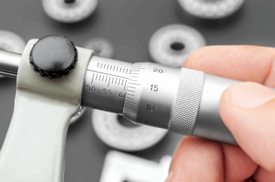
5. Inspection and Finishing

Once the hole reaches the desired diameter, its dimensions and shape are measured to ensure they meet design requirements and objectives.

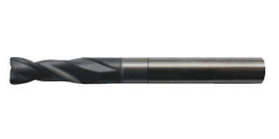
Structure of Spiral Reamer

A spiral reamer consists of the following key components:

1. Cutting Edge Portion

The cutting edge section features cylindrical cutting edges arranged in a spiral pattern. This arrangement facilitates efficient cutting and chip removal while reducing edge wear.

2. Shank Portion

The shank connects the spiral reamer to a tool like a handle or drill chuck. It enables the rotation of the cutting-edge portion.

3. Blade Part

The blade section, situated between the cutting edge and shank, is cylindrical and performs the cutting action within the hole.

Types of Spiral Reamers

Spiral reamers come in various types, each suited to specific applications:

1. Straight Shank Type

This type has a straight shank and a spiral cutting portion. It is used with straight-shank drill chucks or collet chucks.

2. Taper Shank Type

Taper shank spiral reamers feature a tapered shank and are suitable for use with machines like lathes.

3. Short Reamer

Short reamers have a shorter cutting section and are ideal for machining short holes, offering ease of control in confined spaces.

4. Long Reamer

Long reamers are used for drilling deep holes with their extended cutting section, reaching into the workpiece.

5. Hand Reamer

Hand reamers are manually operated and are valuable for precision work and finishing.

6. Machine Reamer

Machine reamers are designed for use with automated machining equipment, ensuring efficient and accurate machining.

7. Ball End Mill Reamer

This type combines features of a ball end mill and a reamer, featuring a spherical cutting portion suitable for machining curved surfaces and circular holes.

Other Information on Spiral Reamers

1. Advantages of Spiral Reamer

Cutting Capacity
The spiral reamer’s advantage is its high-cutting ability. Its special blade spiral structure lowers cutting resistance, improves cutting speed, and also facilitates the discharge of chips.

Rigidity and Stability
Spiral reamers are strong and rigid tools. Even under high cutting loads, vibration and distortion are minimized, enabling high-precision hole drilling.

Finish Quality
Another advantage of spiral reamers is the high quality of hole finishing. Good hole diameter accuracy and uniform surface finish ensure that the required hole dimensions and surface conditions can be met.

Long Life
Spiral reamers are durable and have a long service life. Especially when they are coated with high-quality hard metal or coating, wear and deterioration of cutting ability are reduced. Therefore, high performance can be maintained even when working continuously for long hours or processing hard materials.

Wide Range of Applications
Spiral reamers are used in a wide variety of applications. For example, they are used for drilling holes in metals and plastics, drilling precision positioning holes, and drilling holes with special geometries. Their versatility and flexibility make them convenient for application in a wide range of industries and manufacturing processes.

2. Disadvantages of Spiral Reamers

Expensive
Spiral reamers are relatively expensive due to the need for high-quality materials and special designs. In particular, larger sizes and special specifications are more expensive, so the initial investment and replacement cost may be higher than for other reamers.

Restrictions on Use
Because spiral reamers are optimized for a specific material or hole size range, optimal cutting conditions and performance may be difficult to obtain when used with different materials or hole sizes. In addition, machining holes with special geometries or deep holes requires special ingenuity and equipment.

Chip Management
Spiral reamers generate a large amount of chips during cutting. If chips are not properly disposed of, the working environment and the cutting ability of the machine may be adversely affected. It is necessary to manage chips by cleaning regularly and using appropriate cutting fluid.

3. Improving Cutting Performance

The cutting performance of spiral reamers may be improved by the shape and coating of the cutting edge and the setting of the helix angle. Optimal cutting conditions, especially for hard materials and deep hole drilling, will result in high cutting performance.

4. Special Applications of Spiral Reamers

Spiral reamers are used as tools for specific applications by changing their shapes and coatings. For example, by making the tip of a spiral reamer spherical, a ball end mill reamer can be used for spherical machining.

5. Combination With Automatic Machining Equipment

Spiral reamers can be used in combination with automatic reamers. Since automatic processing equipment can accurately control the machining dimensions and position, it is a good match for precision tools such as spiral reamers, and the combination of both can improve machining accuracy and work efficiency.

カテゴリー
category_usa

Audio Signal Processor

What Is an Audio Signal Processor?

Audio Signal Processors

As the name implies, it is an intermediary device that adds a correction process to the signal output from the sound source to produce ideal sound from the amplifier speakers.

Its primary use is in building in-car audio systems. It acts as an acoustic device when a standard car navigation system is used as the sound source. It enhances realism by correcting the sound range affected by noise and glass reverberation, preventing the desired sound from being hindered.

Uses of Audio Signal Processors

Audio processors are employed to correct digital sound signals in various applications, including car audio accessories, electric instrument output adjustment, synthesizers, vocal effects, Hammond organs, live venues, console rooms, and more.

For example, in vocals, they can suppress crackling sounds or emphasize low frequencies. In guitars, they can produce short, rapid riffs with consistent texture. On the speaker side, they can prevent excessive input signals when handling limited simultaneous sounds.

Principles of Audio Signal Processors

The core function of an audio processor (also referred to as OPS for short) is to correct the transmission of digital sound signals, a process known as time alignment.

When listening to two or three speakers installed in a car with the driver in the driver’s seat, there is an imbalance in the listening point, where one speaker is farther away than the other. This creates a time lag in the left and right outputs, making it seem like you are listening from the center. The closer speaker outputs slightly later, so they reach your ears simultaneously.

This balance is inevitably disrupted when listening in a car, causing twin guitar dialogues, for example, to sound flat when heard from the driver’s seat.

The edgy riff backing at the bottom and the smooth solo at the top need to be positioned at the same level to sound impressive. OPS corrects the signal to restore the best listening experience.

カテゴリー
category_usa

Conductive Container

What Is a Conductive Container?

Conductive Containers

Normal containers are prone to becoming electrically charged. In contrast, a conductive container is crafted with a conductive material blended into it. Ordinary containers, typically made of non-conductive materials like plastic, such as polypropylene, are susceptible to electrical charging, making them unsuitable for certain applications. Charged containers generate static electricity, posing a risk for electronic and semiconductor components, which are sensitive to static discharges.

Conductive containers, on the other hand, prevent static charge and dust accumulation. Due to their grounding, conductive containers do not accumulate static electricity and, consequently, do not attract airborne dust particles.

Uses of Conductive Containers

Conductive containers are primarily employed for electronic and semiconductor components. As previously mentioned, these containers are indispensable for protecting electronic and semiconductor components from the detrimental effects of static electricity. They come in various sizes, ranging from less than 1 liter to approximately 80 liters, suitable for storing semiconductor chips and other electronic parts. Larger containers serve as storage solutions for electrical and electronic components and are used as returnable containers within manufacturing facilities.

Conductive containers are also utilized for products that demand a contamination-free environment. The absence of static electricity prevents dust and foreign particles from adhering to the containers, making them ideal for industries requiring pristine conditions. Additionally, conductive containers are employed for the safe transportation of electronic circuit boards.

Characteristics of Conductive Containers

Conductive containers are typically crafted from plastic materials infused with conductive substances. Common plastics used for these containers include polypropylene and polycarbonate. These materials are chosen for their strength and lightweight properties. However, being non-conductive by nature, they can accumulate electrical charge through friction. To address this, conductive containers are manufactured by incorporating conductive materials like carbon into these plastics, preventing charge buildup. This dispersion of conductive material throughout the container enables static dissipation through grounding.

It is essential to note that conductive containers may lose their effectiveness if placed on highly insulating materials. While the conductive material is mixed into the container, it retains its conductive properties even when the surface is wiped or rubbed. Nevertheless, like ordinary containers, conductive containers may experience gradual deterioration from factors like ultraviolet radiation, particularly if exposed to direct sunlight. To maintain their performance, it is advisable to store these containers away from direct sunlight when used over extended periods. Additionally, placing a conductive container on a rubber sheet or highly insulating material hinders the dissipation of electricity and may not effectively eliminate static even when using conductive containers.

カテゴリー
category_usa

Diamond End Mill

What Is a Diamond End Mill?

Diamond End Mills

A diamond end mill is a cutting tool that employs diamond as its cutting-edge material.

Diamond possesses exceptional hardness and heat diffusion properties, making it an ideal choice for cutting tool material. Over 80% of natural diamonds are used in industrial applications, and the majority of synthetic diamonds are produced artificially. Synthetic diamonds, also known as lab-grown diamonds, are artificially created from carbon and other materials.

Diamond end mills exhibit remarkable longevity when machining materials like graphite, Carbon Fiber Reinforced Plastic/Glass Fiber Reinforced Plastic (CFRP/GFRP), ceramics, and more.

Uses of Diamond End Mills

Diamond end mills can create “sharp cutting edges” when their cutting edges are ground. These cutting tools leverage diamond’s properties to enable ultra-precise, exceptionally long-lasting, and high-performance machining.

Diamonds used in cutting tools are categorized as monocrystalline and polycrystalline diamonds, with monocrystalline diamonds further divided into natural and synthetic diamonds.

Monocrystalline diamonds are known for their high hardness, excellent heat diffusion, and sharp cutting edges. In contrast, polycrystalline diamonds are composed of small single crystals oriented in various directions. This irregular structure makes them resistant to force from any direction, and they are characterized by their durability and resistance to chipping and delamination.

Principles of Diamond End Mills

Diamond end mills are cutting tools that can be mounted on machining centers and milling machines. They are well-suited for machining nonferrous metal materials such as aluminum alloys and copper alloys, as well as non-metallic materials like wood, plastic, and molded ceramic materials.

It is advisable to avoid machining ferrous materials due to their affinity for iron. Additionally, diamond end mills have low toughness, so machining with impact should be approached with caution.

In various industries such as machinery and electronics, there is a growing trend towards higher efficiency and precision in cutting. This has led to the increased adoption of diamond tools. For instance, in the automotive industry, the use of diamond tools has been rising due to the need for highly efficient machining to enhance productivity and the increased utilization of aluminum alloys to reduce vehicle body weight.

Sintered diamonds, produced by hardening diamond powder under ultra-high pressure and high temperature, possess high hardness and toughness, making them widely used as cutting tools and wear-resistant components.

Recent years have witnessed a surge in demand for diamond tools as machining becomes more efficient and precise, and materials become increasingly diverse and challenging to machine.

カテゴリー
category_usa

Bushing

What Is a Bushing?

Bushings

In a broader context, a bushing is used to fill gaps between parts. Bushings are frequently employed in machine and bearing components.

Bearing components constantly experience friction with the rotating shaft during machine operation. Even when grease or other lubricants are used to mitigate wear, it cannot be entirely eliminated.

As a result, it becomes necessary to rejuvenate the worn parts. By utilizing bushings, functionality can be restored simply by replacing the parts.

Uses of Bushings

Here are examples of applications for bushings:

  1. Automobile suspension arm joints
    Friction arises between the suspension arms and the car body due to vibrations while the car is in motion and between the arms themselves. To reduce vibration, rubber bushings are used at these joints. Over time, as the rubber material deteriorates, vibration and wobbling may occur during driving.
  2. Linkage between the motor and arm
    In motors used for lid opening and closing applications, oilless bushings are often placed in the mounting hole of the arm that connects the lid to the motor. This is because replacing the arm itself would be a major undertaking.

Principles of Bushings

There are two types of bushings: oilless and oiling, each with different characteristics.

  1. Oilless bushings
    Since regular lubrication is not required, this type of bushing is often used in places where lubrication is challenging. However, it is more susceptible to wear, requiring more frequent replacement.
  2. Oiling bushings
    Regular lubrication reduces wear and the need for replacement. Neglecting lubrication, on the other hand, shortens their lifespan, emphasizing the importance of maintenance. The use of an automatic lubricator can eliminate the need for manual maintenance.

Bushing strength varies based on the material used, so appropriate selection is crucial depending on the intended application.

For general machine components, selecting a material with high strength for wear resistance is straightforward. However, bushings are designed to be replaced.

If bushings are too strong, they won’t wear out, but the main body components will, increasing the cost and effort required for part replacement.

Therefore, appropriate materials for bushings should be selected with consideration for the materials of the main body components.

カテゴリー
category_usa

Micrometer Head

What Is a Micrometer Head?

Micrometer Heads

A micrometer head is the part of the micrometer that moves and touches the object to be measured when the micrometer pinches the object. Typically, the head is moved by rotating a knob on the head part to pinch the object to be measured. In addition to being able to measure visually, many digital micrometer heads are now on the market. The tip is usually cylindrical, but there are also conical, spherical, flange-shaped, and other products.

Uses of Micrometer Heads

Micrometer heads are used for inspecting and maintaining industrial equipment and products and for dimensional measurement of test objects in laboratories and research laboratories. They are used for products that require higher precision measurements than those made with calipers, etc. When selecting a micrometer head, it is necessary to consider measurement accuracy, ease of error, whether it is a digital or analog type, and ease of maintenance. Note that micrometer heads measure by contact and are not suitable for measuring rubber and other materials whose shape is deformed by contact.

Principles of Micrometer Heads

The features of the micrometer heads are described below. The micrometer heads consist of a measuring section, spindle, mounting section, graduated sleeve, coarse knob, and fine knob. The rough and fine knobs are connected to the spindle by a gear, which causes the spindle to move following the rotation of the knob. Generally, the fine control knob is also equipped with a scale, enabling measurement of even finer amounts. In the mounting area, products are available with mounting methods such as tightening using screws, nuts, or mortises.

When taking a reading, the spindle moves the coarse knob to contact the object to be measured lightly. Then, by adjusting the fine control knob, the spindle is brought into complete contact with the object to be measured. The fine adjustment knob is a mechanism that prevents the spindle from advancing after making contact, allowing it to rotate until it makes complete contact. The measurement can then be made by examining the scale on the sleeve and the scale on the fine control knob.

Examples of Micrometer Heads Use

The micrometer heads are used for adjusting the movable range of multi-axis stages, etc., and for inspecting jigs for large quantities of parts that need to be inspected.

Micrometer Heads Clamp

The micrometer heads can be used as a clamp by using a stopper that matches the range of motion. Selecting a product with a clamp is also recommended depending on the product. Choosing a product with a clamp will prevent the loosening of the operation.

How to Fix the Micrometer Heads

The method of fixing the micrometer heads depends on whether the micrometer head mounting stem is a straight type or a nut type.

  • How to fix a straight type: Use a split part on the bearing side and clamp it to the mounting shaft with a screw or the like. Pass the mounting shaft through the hole in the bearing side and fix it with a set screw.
  • Fixing method for types with nuts: Pass the mounting shaft through the hole on the bearing side and secure with the nut attached.

Load Capacity of Micrometer Heads

The load capacity of micrometer heads varies depending on the conditions of use, such as mounting method, static load, or dynamic load, and whether the micrometer heads are used in operation or as a stopper. Therefore, there is no quantitative definition.

As an example, recommended load capacity limits are listed below.

Load capacity of micrometer heads

  • Standard type (spindle pitch 0.5 mm): up to about 4 kg
  • High-performance type spindle pitch 0.1 mm/0.25 mm: up to approx. 2 kg
  • High-performance type spindle pitch 0.5 mm: up to approx. 4 kg
  • High-performance type, spindle pitch 1.0 mm: up to approx. 6 kg
  • High-function type Spindle pitch linear type: up to approx. 2 kg
  • High-function type MHF for ultra-fine adjustment (with differential mechanism): up to approx. 2 kg

Static load by mounting method

  • Tightening nut method: 8.63 to 9.8 kN (880 to 1000 kgf) or main unit breakage
  • Slit-split fastening method: 0.69 to 0.98 kN (70 to 100 kgf) for falling off from the mounting bracket
  • Screw fixing method: Damage to set screw at 0.69 to 1.08 kN (70 to 110 kgf)


カテゴリー
category_usa

Power Factor Correction (PFC) Equipment

What Is Power Factor Correction (PFC) Equipment?

A power factor correction (PFC) equipment is a specialized controller used to manage PFC equipment, which plays a crucial role in improving the power factor of electrical systems.

The power factor represents the ratio of active power to apparent power in an AC circuit. When AC voltage is supplied to a system with capacitive or inductive loads, it can result in phase differences in input current and the distortion of the waveform, leading to the generation of harmonic currents that negatively impact the power factor.

PFC equipment, which includes a PFC circuit, is designed to mitigate these issues, bringing the power factor closer to 1. A PFC controller is employed to regulate and control the PFC circuit.

Uses of Power Factor Correction (PFC) Equipment

PFC equipment is essential in AC-DC converters, which transform AC commercial power into DC. In cases where electronic equipment has a low power factor, it imposes an additional burden on power companies and other suppliers, as they need to provide extra power beyond what the load consumes.

Furthermore, harmonic currents caused by low power factors can damage power transmission and distribution equipment. International standards, such as IEC61000-3-2, set limits for harmonic currents, and electronic devices must adhere to these regulations.

Therefore, the use of PFC equipment is crucial to ensure compliance with these standards and to improve the power factor.

Principle of Power Factor Correction (PFC) Equipment

Power factor correction begins with the rectification of AC voltage by a diode bridge in an AC-DC converter. The voltage is then smoothed using a capacitor and converted into DC voltage. However, during this process, a phase difference develops between the voltage at both ends of the capacitor and the current flowing through it, leading to a phase difference between input voltage and current.

Additionally, because no current flows during the period when the input AC voltage is lower than the voltage at both ends of the capacitor, and charging current only flows during the period when the input AC voltage is higher, it results in a distorted current waveform, generating harmonic currents. These phase differences and harmonic currents are detrimental to the power factor.

To enhance the power factor, a PFC circuit is inserted between the diode bridge and the smoothing capacitor. This circuit, which operates similarly to a boost-type DC-DC converter, controls the switching elements to shape the input current waveform closer to a sine wave.

Structure of Power Factor Correction (PFC) Equipment

The PFC equipment’s circuit consists of components such as an inductor, a field effect transistor (FET), and a diode. The FET is a type of transistor that, when turned on or off, rapidly changes the current in the inductor. However, the inductor’s property of slowing down current changes results in a triangular wave for the current. Repeated switching control ensures the current waveform approximates a sine wave, enhancing the power factor.

Other Information on Power Factor Correction (PFC) Equipment

1. Circuit Method of PFC Circuit

Two main PFC circuit methods exist: a single method with one set of switches and an interleaved method with two sets of switches that can suppress ripple current by operating them with a 180-degree phase shift. Additionally, there are two operating modes: continuous current mode (CCM) for high-power applications (200 to 500 W) and current critical mode (CRM) for medium-power applications (100 to 200 W). The selection depends on the specific purpose and application requirements.

2. Active Power and Apparent Power

  • Active Power
    This represents the power consumed by the load and is not returned to the source (reactive power).
  • Apparent Power
    Apparent power is the product of the root mean square (RMS) voltage and RMS current applied to the load. Both active and reactive power components are derived from apparent power. Therefore, the sum of active and reactive power equals apparent power.
カテゴリー
category_usa

Rolled Ball Screw

What Is a Rolled Ball Screw?

Rolled Ball Screws

A ball screw is a component that converts a motor’s rotational power into linear or linear power into rotational power. It consists of a threaded part and a moving part. It is mainly used for linear motion.

Among ball screws, there are two types: rolled ball screws and ground ball screws. Ground ball screws offer higher precision. In addition, ball screws are divided into two types, one for positioning and the other for conveyance, each of which is determined by its accuracy.

Uses of Rolled Ball Screws

Ball screws are classified into two types according to their accuracy, of which there are many more accuracy grades. Grades C0 to C5 are used for positioning. For conveyance applications, grades C7 and C10 are used.

Ball screws are mainly used in industrial robots, machine tools for positioning and conveyance, and semiconductor manufacturing equipment. They are often used to convert the rotational motion of a motor into linear motion. The load itself is applied from the axial direction only. Therefore, a guide is required.

Principles of Rolled Ball Screws

A ball screw consists of a screw shaft, nut, and ball. The ball is placed between the screw shaft and the nut and rolls lightly. The action is such that the balls circulate endlessly. The most common type is the return plate type. The ball that has come to an end passes through the plate and returns to the tip again to perform a rolling motion.

The following is a description of the manufacturing process of rolled ball screws. A round bar is used as the steel material. The steel material is a round bar threaded by a tool called a rolling die while being rotated. The threading is done by combining two rolling dies.

In addition to rolled ball screws, there are ground ball screws. In a ground ball screw, the thread grooves are created by grinding cylindrical steel. Therefore, they can be manufactured with higher precision than rolled ball screws. The disadvantage is that it is more expensive. Axial clearance is also reduced.