カテゴリー
category_usa

Spectroradiometer

What Is a Spectroradiometer?

A spectroradiometer is a device that analyzes the light emitted by a material across various wavelengths and frequencies. By distinguishing light’s spectral radiance, it determines the composition and characteristics of substances. Even if two light sources appear the same color to the human eye, they can have different spectral radiances. Therefore, to avoid discrepancies in perceived colors under different lighting conditions, a Spectroradiometer is essential for accurately measuring these differences.

Uses of Spectroradiometers

Spectroradiometers are used in diverse fields, such as:

  • Chemical analysis for substance composition analysis.
  • Materials research, environmental monitoring, and life sciences.
  • Astronomy for analyzing celestial objects.
  • Characterization of displays and lighting products, ensuring accurate color reproduction under various conditions.

Features of Spectroradiometers

Spectroradiometers measure light in terms of spectral radiance, expressed in units of W/sr/m2/nm-1 (watts per steradian per square meter per nanometer). They distinguish between different intensities of light based on wavelength, breaking down light into its spectra using a diffraction grating. The received light is converted into electrical signals to calculate spectral radiance. Most spectroradiometers also calculate other values such as luminance, tristimulus value XYZ, and chromaticity coordinate xy.

Types of Spectroradiometers

Various types of Spectroradiometers include:

1. Spectrophotometer

Measures light absorption at specific wavelengths and quantifies the absorbance. Commonly used for analyzing substance concentration and reaction progress.

2. Spectrofluorometer

Measures fluorescent light re-emitted upon light excitation absorbed by a substance. Utilized for analyzing substance properties and concentrations.

3. Spectro-Infrared Analyzer

Analyzes composition and structure by measuring the infrared spectrum absorbed by a substance. Employed in chemical analysis and materials research.

カテゴリー
category_usa

Spectrophotometers

What Is a Spectrophotometer?
Spectrophotometers

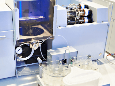
A spectrophotometer is a device that can connect to various wavelengths, irradiate spectral light onto a sample, and examine the wavelength and amount of light transmitted through and reflected from the sample. Spectrophotometers are common, versatile analytical instruments used in various fields, including research and development, quality control, and chemical analysis.

Typical instruments include Vacuum Ultraviolet Spectrophotometers (VUV), Ultraviolet-Visible Spectrophotometers (UV-Vis), and Infrared Spectrophotometers (IR), each capable of obtaining different information by using light in distinct wavelength ranges.

Uses of Spectrophotometers

Spectrophotometers Are Used in Design, Color, Paint, and Other Color-Related Industries

Spectrophotometers are used in various industries that rely on color-related measurements. For instance, in the automotive industry, spectrophotometers are employed to inspect the quality of car bodies after coating, as the design and color of cars are crucial.

In the paint industry, spectrophotometers are used to assess the color quality of paints to ensure they achieve the desired color.

Spectrophotometers Are Also Used for Quality Control

Other industries, such as the food and design sectors, where product appearance is critical, utilize spectrophotometers for color evaluation as part of their quality control processes.

Principle of Spectrophotometers

Spectrophotometers detect the light transmitted or reflected from a sample and generate a corresponding spectrum. Analyzing these spectra provides various information about the sample, such as quantitative analysis based on peak intensities, qualitative analysis from spectral waveforms, and evaluations of electronic states, molecular structures, and material properties.

The instrument primarily consists of a light source, a spectroscope section, a sample section, and a detector. The light source emits light for analysis, with deuterium discharge tubes used for the ultraviolet region and tungsten lamps for the visible and near-infrared regions being the two primary light sources.

The spectroscope selects specific wavelengths of light from the light source and is available in filter, prism, and diffraction grating types.

The sample section contains a cell that holds the sample to be measured, primarily made of glass or quartz.

The detector converts the light transmitted from the sample into an electrical signal.

Types of Spectrophotometers

Spectrophotometers irradiate a sample with light to examine the wavelength and absorption of the transmitted and reflected light. Several types of instruments are available, depending on the light source. This section provides an overview of three types of spectrophotometers: Vacuum UV Spectrophotometer, UV-Visible Spectrophotometer, and Infrared Spectrophotometer.

1. Vacuum Ultraviolet Spectrophotometer (VUV)

The vacuum ultraviolet spectrophotometer uses light in the vacuum ultraviolet region (200 nm or less) as a light source to examine light transmitted through or reflected from a material. Since light in the vacuum ultraviolet region is absorbed by oxygen and nitrogen molecules, measurements must be conducted in a vacuum. This type of spectrophotometer is used to evaluate material properties.

2. UV-Visible Spectrophotometer (UV-Vis)

This device uses ultraviolet light (200-380 nm) and visible light (380-780 nm) as light sources to examine light transmitted through and reflected from a material. It allows for qualitative and quantitative analysis of sample components.

3. Infrared Spectrophotometer (IR)

Two types of IR spectrophotometers exist: near-infrared (780-2500 nm) and mid-infrared (2500-25000 nm). These spectrophotometers can estimate molecular bonds, and functional groups, and perform quantitative analysis of sample components.

Special spectrophotometers include the Raman spectrometer, which detects Raman light scattered from a sample to identify molecular structures and evaluate material properties, and the Fourier Transform Infrared Spectrophotometer (FTIS), which uses an interferometer to simultaneously detect non-dispersive light at all wavelengths and perform Fourier transformation to calculate components at each wavelength. Fourier Transform Infrared Spectroscopy (FT-IR) is also available.

Other Information on Spectrophotometers

1. Single Beam and Double Beam

The optics of spectrophotometers vary widely based on their purpose. As an example, we will discuss single-beam and double-beam systems.

Single-beam (monochromatic) optics refer to an optical system in which monochromatic light (light of a single wavelength) spectrally illuminated by a monochromator is directed onto a sample, and the reflected or transmitted light is detected by a detector. While single-beam systems have a simple optical configuration and are relatively cost-effective, they may not be suitable for highly accurate measurements due to larger measurement errors.

The double-beam method improves on these disadvantages. In the double-beam method, the light spectra from the monochromator are divided into sample light and reference light by a half-mirror or similar component. The sample light illuminates the sample, and the reflected or transmitted light is detected by a detector, similar to the single-beam method.

Since both the reference light and sample light contain errors attributed to the instrument, the signal from the reference light is processed alongside the signal from the sample light to cancel out these effects.

2. Difference Between a Spectrophotometer and a Colorimeter

Colorimeters are used for various purposes, but here we will discuss two typical types: colorimeters (color difference meters) and spectrophotometers.

  • Colorimeter (Color Difference Meter)
    A colorimeter is based on the direct reading method of stimulus values. When the human eye perceives colors, it receives stimuli from sensors (cones) in the retina and reads the three stimulus values of red (X), green (Y), and blue (Z). Colorimeters directly measure these three stimulus values using physical filters with response characteristics equivalent to human visual angle characteristics. They are widely used in production and manufacturing to assess color differences from the actual product (color sample).
  • Spectrophotometer
    A spectrophotometer, also known as a colorimeter, is a colorimeter based on the spectrophotometric method and is a type of photometer that measures the intensity of light. Reflecting light from the object is broken down into a spectrum for each wavelength by a spectral sensor and measured. Tri-stimulus values are calculated from this spectral characteristic. By defining spectral characteristics (spectral values) as color reference values, highly accurate color management can be performed with digital values even without actual samples. Due to challenges in managing actual samples (color samples) like variation and deterioration over time, color management using a spectrophotometer as a reference color (digital value) has become the mainstream method.

3. Daily Maintenance Guidelines for Spectrophotometers

One of the issues that can disrupt measuring instruments is maintaining and ensuring their accuracy. Spectrophotometers are no exception. It is essential to perform daily inspections as it is too late to take countermeasures after a failure has occurred.

Here are some important indicators for spectrophotometers that should be checked daily to detect abnormalities early:

  • Wavelength Accuracy: This refers to the error between the wavelength detected by the device and the light source wavelength.
  • Wavelength Repeatability: Wavelength repeatability measures the variation in wavelength when the same wavelength is measured repeatedly.
  • Resolution: Resolution evaluates the bandwidth when measuring monochromatic light and is typically managed by Full Width at Half Maximum (FWHM).
  • Stray Light: Stray light refers to light, other than the target wavelength, obtained from the device.
カテゴリー
category_usa

Freeze Dryers

What Is a Freeze Dryer?

Figure 1. Structure of a freeze dryer

Figure 1. Structure of a freeze dryer

A freeze dryer is a device used to remove water from a sample while it is in a frozen state.

There are three fundamental equipment configurations:

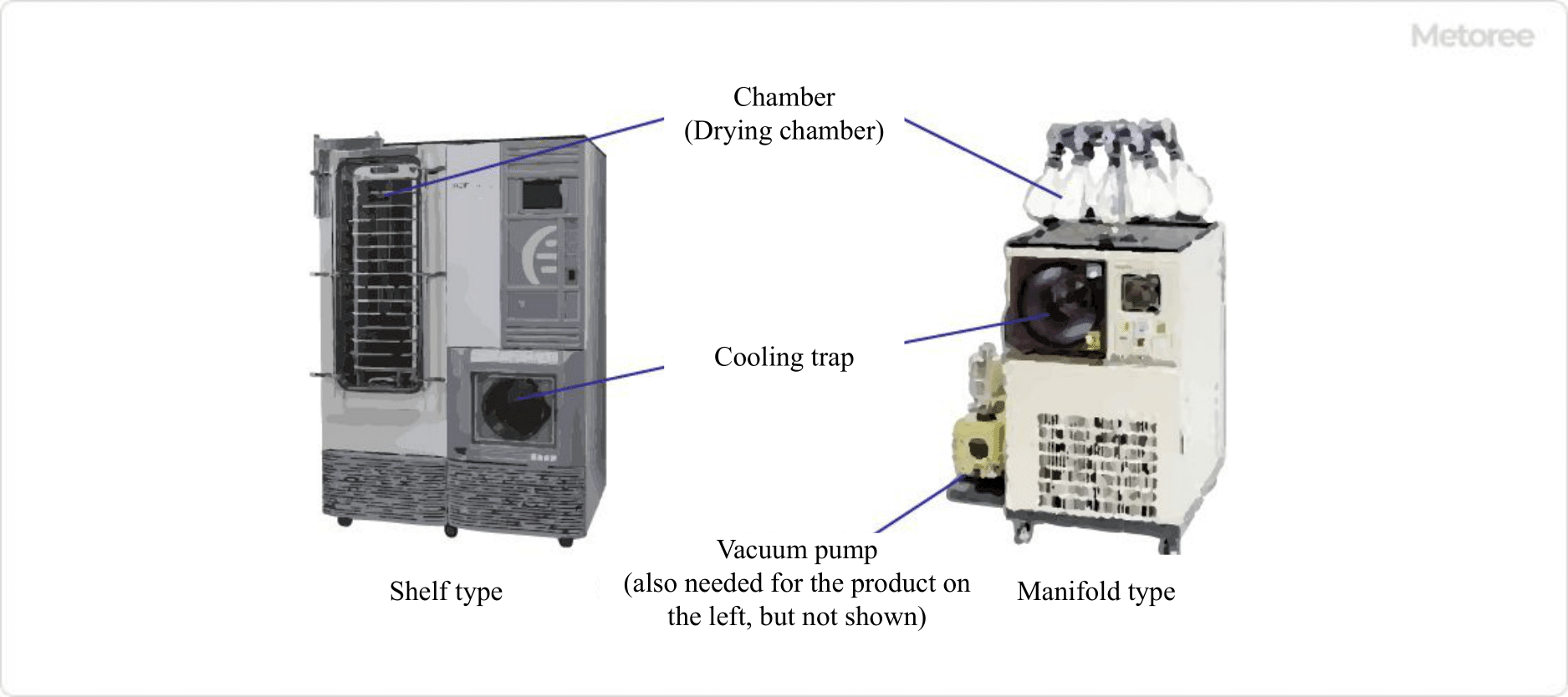
  • Chamber (Drying Chamber): Stores and dries the sample.
  • Cooling Trap: Collects vapor that has been vaporized in the condenser and condenses it again.
  • Vacuum Pump: Reduces the pressure inside the device.

This system removes water and solvents by depressurizing pre-frozen samples in the chamber and sublimating ice, allowing for drying while minimizing structural changes.

Uses of Freeze Dryers

Freeze dryers are used for materials that can deteriorate due to moisture when stored at room temperature, in refrigerated storage, or frozen storage for an extended period.

Freeze-dried samples can be stored at room temperature for an extended period if properly sealed. Moreover, the cost of equipment maintenance during storage is lower compared to other storage methods.

Specific uses of this method include:

1. Food Products

Freeze-dried foods, such as instant coffee, miso soup, and space food, can be stored for an extended period, are suitable for transportation due to their dry and lightweight nature, and maintain their flavors well.

2. Pharmaceutical Products

Freeze dryers are used to produce injectable drugs like heat-sensitive proteins and enzyme preparations due to their ability to create powder without heating. Research is also underway to preserve animal sperm using freeze dryers.

Principle of Freeze Dryer

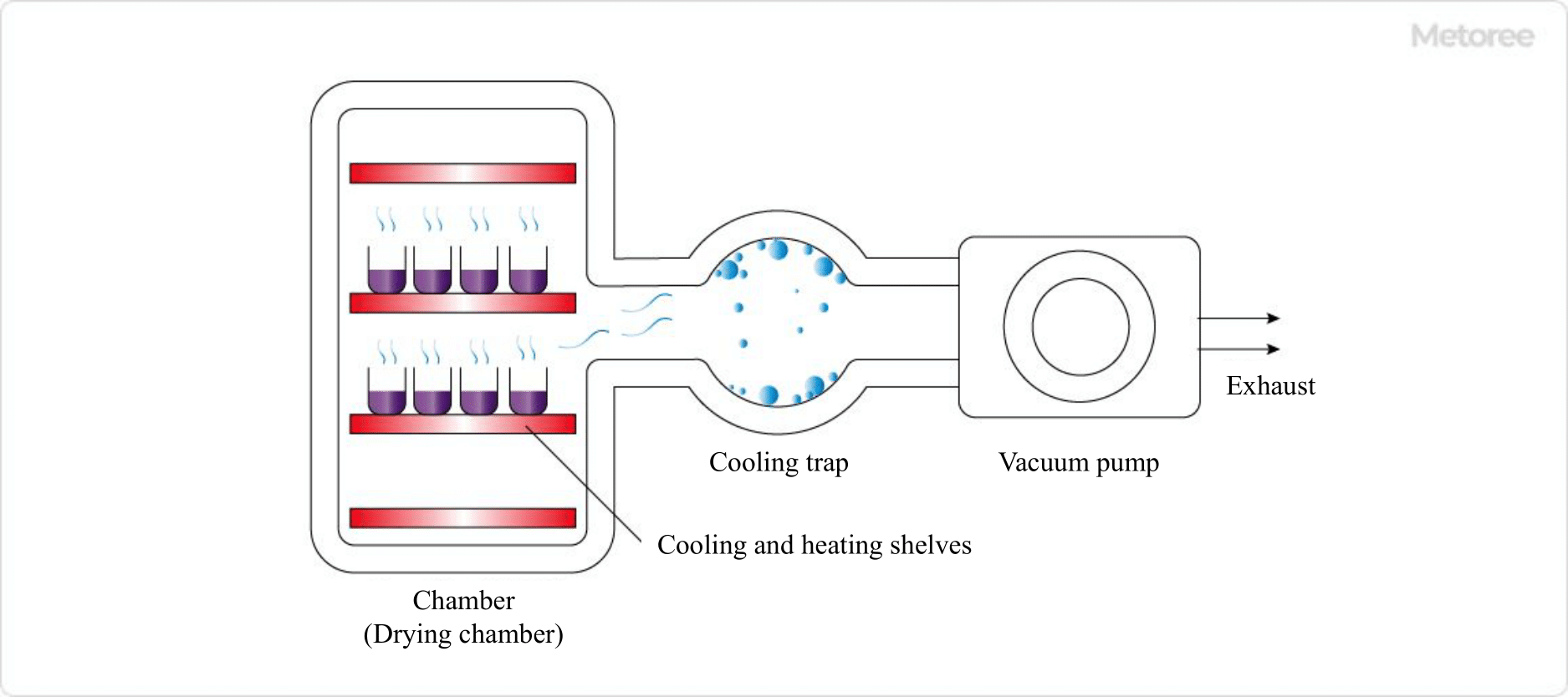
Figure 2. Schematic diagram of a freeze dryer

Figure 2. Schematic diagram of a freeze dryer

The freeze-drying process involves the following steps:

  1. Pre-freeze the sample to freeze it thoroughly.
  2. Store the frozen sample in the chamber (drying cabinet).
  3. Primary freezing: A vacuum pump is used to reduce the pressure inside the chamber, allowing the solvent to sublimate from the sample. In the shelf type, heat energy lost during sublimation is compensated for by heating the shelf, enabling efficient drying.
  4. Secondary freezing: In the shelf type, the shelf temperature is raised to remove bound water that has been incorporated into the solute components. This is a relatively short process.
  5. Release the decompression and remove the sample. In the shelf-type freeze dryer, vials can be stoppered before decompression is released by using a stoppered shelf and stoppered vial.

The sublimated water vapor is cooled in a device called a cooling trap and collected as ice again. The faster drying occurs when there is a greater temperature difference between the drying chamber and the cooling trap.

For food products, they are easy to dissolve and rehydrate with water or boiling water. However, once the seal is broken, they are prone to oxidation, moisture absorption, and quicker deterioration.

Types of Freeze Dryers

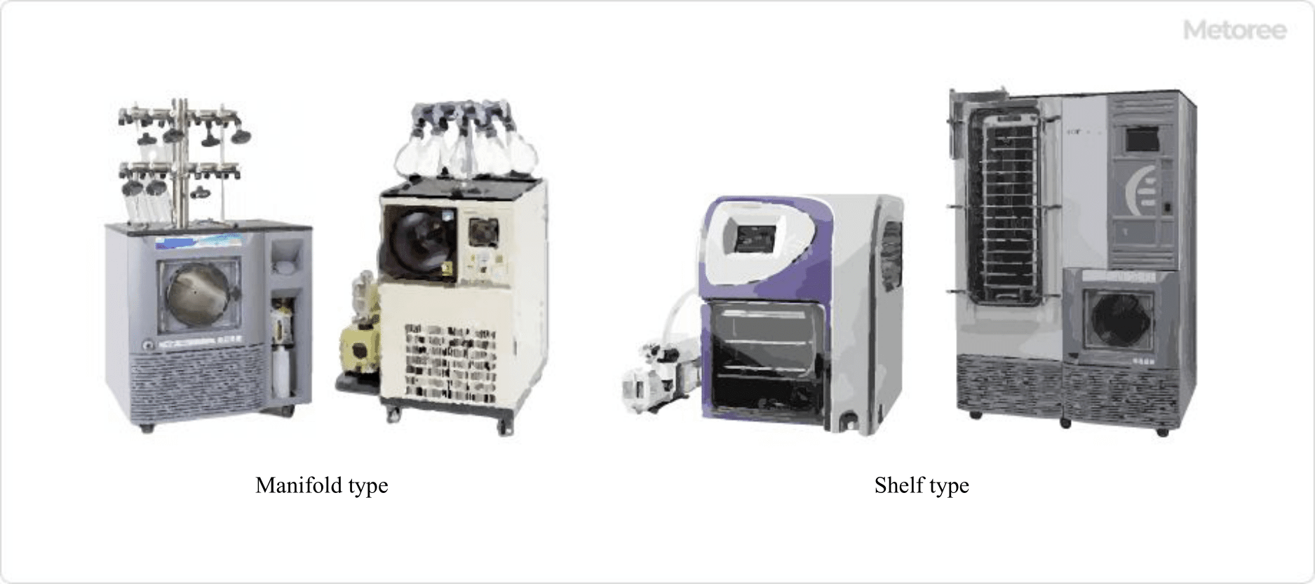
Figure 3. Various freeze-drying machines

Figure 3. Various freeze-drying machines

There are two primary types of freeze dryers: “manifold type” and “shelf type.”

They come in various sizes, from small ones used for laboratory research to large ones for manufacturing purposes. Drying capacities range widely, from 150 mL for small models to over 100 L for large models.

1. Manifold Type

The manifold type is relatively small in scale and primarily suitable for basic research, whereas the shelf type can be used on a broader scale.

2. Shelf Type

Shelf-type freeze dryers can control temperature by heating the shelves. They can efficiently compensate for the thermal energy required for sublimation, making them suitable for drying samples. Some shelf plate-type products also have a stoppering function. By using stoppering vials as sample containers and operating the stoppering shelf, the chamber can be automatically stoppered while maintaining a vacuum.

カテゴリー
category_usa

Cooling Coils

What Is a Cooling Coil?

A cooling coil is a component used in a heat exchanger. It consists of piping formed into a spiral shape, although other shapes are also available and designed based on specific equipment and purposes.

Water is primarily used as the refrigerant in cooling coils. Since the refrigerant flowing through the cooling coil gets heated due to heat exchange, it’s essential to lower its temperature. For this purpose, cooling coils are often used in conjunction with chillers.

Uses of Cooling Coils

Cooling coils are employed to regulate the water temperature in water tanks and help lower the tank temperature during temperature spikes, such as in the summer.

They are also utilized to control the temperature of liquids used as raw materials in various factory equipment. Cooling coils are directly immersed in the liquid to be cooled, making them highly efficient for cooling and ensuring stable temperature control. Maintaining a constant temperature of raw materials is crucial to prevent changes or increased reactivity, resulting in inconsistent products. Cooling coils play a pivotal role in temperature control to avoid such issues.

Principle of Cooling Coils

Efficiently removing heat from a hot object and cooling it down involves several key factors. First, a liquid with high heat capacity and low temperature should flow as rapidly as possible. Additionally, the surface area of the piping through which the refrigerant flows should be increased. Agitation is also effective when dealing with hot liquids or gases. Cooling coils have intricate shapes, such as spirals, to enhance the surface area of the piping and improve cooling efficiency.

Piping for cooling water is often made of copper, which is an excellent material with high thermal conductivity. It is cost-effective and easy to process. However, copper is susceptible to corrosion and heat. Therefore, when cooling targets involve liquids or gases that can corrode copper or are at high temperatures, more durable materials like stainless steel are used.

The amount of heat removed from the object being cooled can be easily calculated based on the volume of water flow and the measured temperature increase. For example, if the temperature of the cooling water rises by 1°C when 1 liter of cooling water flows per minute, it removes 1 kcal of heat per minute.

While water is commonly used as a refrigerant, hydrogen is sometimes employed as a gaseous refrigerant due to its high heat capacity and cooling effect.

カテゴリー
category_usa

Inside Micrometer

What Is an Inside Micrometer?

An inside micrometer is a precision measuring instrument designed to measure the inside diameter of hole shapes. It typically features three variations: a three-point measuring instrument for inside diameter, a dial gauge type measuring the extent of element push-in, and a rod-shaped version for measuring larger diameters. Some instrument manufacturers may use the term “Inside Micrometer” exclusively for the rod-shaped type that measures by two-point contact.

Uses of Inside Micrometer

Inside micrometers are primarily used in the manufacturing, quality control, and product development of industrial metal products. They are crucial for measuring not just circular inside diameters but also groove widths and distances. However, due to their structural limitations, they are not suitable for measuring very small diameters or dimensions, where alternative instruments like pin gauges or image measurement systems are recommended.

Principle of Inside Micrometer

The inside micrometer operates by making direct contact with the inside diameter of a hole and reading the distance between the measuring elements. The measurement is typically read from a micrometer or a dial gauge. Rod-shaped inside micrometers measure the inside diameter based on the screw’s forward or backward movement. They lack a ratchet, thus requiring careful application of measuring pressure. The 3-point inside micrometer uses a conical transducer to convert screw movement into the opening and closing of the measuring element, typically equipped with a ratchet for consistent measuring pressure.

Types of Inside Micrometers

1. Hole Test ABS Borematic

This type of inside micrometer measures by inserting the measuring element into the bore and reading the micrometer attached to the spindle. Three-point measuring instruments are known for stable measurements but have a limited measuring range.

2. Inner Micrometer

The rod-shaped inside micrometer measures the inside diameter by contacting the bore with both ends of the instrument. Accurate measurement requires careful positioning and practice.

3. Cylinder Gauge

Cylinder gauges are two-point contact instruments with readings provided by a dial gauge or a digital display. They allow for constant measuring pressure but require attention to the tilt between contact points.

Note that some inside micrometers may also refer to air micrometers and electric micrometers, which measure non-contactually by detecting the gap between the probe and the hole using air or electrical means.

カテゴリー
category_usa

Glossmeter

What Is a Glossmeter?

A glossmeter, also known as a gloss meter, is a device that measures the surface gloss of various materials. It is often available in a handy, portable form. The device operates by measuring the intensity of light reflected in a specific direction, known as specular gloss, to determine the gloss level of a surface. This measurement is crucial for quality control, especially in industries where the visual appearance and color consistency of products are important. By quantifying the gloss, a glossmeter helps standardize the perception of an object’s surface quality.

Applications of Glossmeter

Glossmeters are used to measure the surface gloss of materials like coatings, platings, plastics, enamel, tiles, and paper. They are not suitable for non-smooth surfaces or metallic coatings. The gloss level is expressed as Gs(θ), representing the ratio of the reflected light from the sample to that of a standard glass with a refractive index of n=1.567. θ denotes the angle of light incidence, with standard angles including 20°, 45°, 60°, 75°, and 85°.

Principle of Glossmeter

Glossmeters function by measuring normally reflected light from a non-polarized light source at specific angles on a smooth specimen surface. The reflected light’s intensity is compared to a standard glass, calibrated to 100% reflection at each angle. The device’s sensor section captures the reflected light, which varies depending on the smoothness and shininess of the surface. Gloss levels are categorized as high, medium, or low based on the intensity of the reflected light at a 60° incidence angle.

Types of Glossmeter

Glossmeters come in various types, each suited for different surface gloss levels:

1. 60° Glossmeter

This is the most common type, used for measuring gloss on standard surfaces such as paints and plastics.

2. 20° Glossmeter

Designed for surfaces with very high gloss levels, like mirror finishes.

3. 85° Glossmeter

Suitable for measuring low gloss surfaces, such as matte finishes.

4. Triangular Colorimetric Gloss Meter

This type can measure both color and gloss, allowing evaluation of the relationship between surface color and gloss.

How to Select a Glossmeter

When choosing a Glossmeter, consider factors like measurement range, resolution, ease of operation, functionality, and maintainability. High-resolution models are ideal for detecting subtle gloss changes, while user-friendly interfaces and data management features enhance usability. Regular maintenance is crucial for ensuring long-term accuracy.

カテゴリー
category_usa

Optical Filters

What Is an Optical Filter?

An optical filter selectively allows certain wavelengths of light to pass through while blocking others. Types include bandpass filters, ND (neutral density) filters that reduce light intensity, and infrared filters that block infrared rays. The selection of an optical filter depends on the spectrum and intensity of incident light and the desired wavelength.

Applications of Optical Filters

Optical filters are integral to various technologies, enhancing performance through their diverse characteristics.

1. Cameras

In cameras and imaging equipment, optical filters minimize false colors and diffuse reflection, enabling clearer images. ND and polarizing filters adjust brightness and reflections for optimal imaging.

2. Display Technology

Used in smartphones and TVs, optical filters enhance screen brightness and color reproduction, contributing to improved visual quality.

3. Laser Technology

In telecommunications and medical applications, optical filters refine laser light for specific uses, facilitating precise wavelength selection for a range of applications.

Principle of Optical Filters

Optical filters operate through interference, absorption, reflection, diffraction, and phase shift of light, allowing them to selectively transmit specific wavelengths. Their design involves adjusting materials, film thickness, and layer arrangement to achieve desired optical characteristics, such as in dichroic filters for light polarization and color control, absorptive filters for wavelength-specific light absorption, and interference filters that leverage light wavelength and film thickness for selective transmission.

Types of Optical Filters

Optical filters vary in function and design, each tailored for specific applications:

1. Dichroic Filter

These filters control light polarization and color by reflecting and transmitting light at specific angles and wavelengths, used in projectors and optical splitters.

2. Absorption Filters

These filters absorb light of certain wavelengths, adjusting brightness and reflection in cameras and polarizing filters.

3. Interference Filters

Interference filters precisely select narrow wavelength bands, essential in spectroscopy and laser technology.

4. Phase Shift Filter

Phase shift filters alter the phase of light to control specific wavelengths, applied in spectroscopy and laser technology.

5. Polarization Filters

These filters transmit light of a certain polarization, blocking others, used in LCDs and polarizing microscopes for optical control.

6. Thermal Filter

Thermal filters manage infrared radiation, allowing specific bands to pass while blocking others, crucial for thermal imaging and sensing.

カテゴリー
category_usa

Optical Isolators

What Is an Optical Isolator?

Ultrasonic Welders

Optical isolators are devices that allow light to pass in only one direction, crucial for preventing backward signal transmission in applications like LEDs and optical communications. By integrating with optical fibers and polarizers, they ensure signal stability and security, making them vital in fields such as telecommunications, laser technology, and aerospace.

Applications of Optical Isolators

Used in various settings, optical isolators prevent noise and interference in optical fibers, LEDs, and optical amplifiers by blocking unwanted backward light. Selection criteria include supported wavelengths, accuracy, size, connectivity, and durability.

1. Telecommunication Field

In telecommunications, optical isolators ensure unidirectional signal flow, enhancing signal quality and security.

2. Laser Technology

Key in laser devices, they maintain stability and efficiency by preventing reverse light entry. They are used in devices such as laser diodes and laser resonators.

3. Space Field

High-functionality optical isolators are essential for stable signal transmission and device protection under harsh space conditions.

Principle of Optical Isolators

Operating on the Faraday effect, optical isolators use polarizers or diffraction gratings to allow unidirectional light transmission. They come in two types: polarizer-based, which uses the Faraday effect for polarization, and refraction grating-based, adjusting the refractive index for directional transmission.

1. Polarizer Type

This type employs a Faraday rotator between two polarizers, transmitting light with specific polarization and blocking opposite directional light through polarization rotation correction.

2. Refractive Grating Type

Utilizes a rotator between refractive gratings, enabling directional light transmission by adjusting the refractive index via the Faraday effect.

Characteristics of Optical Isolators

Optical isolators feature high insulation properties, allowing for electrical isolation and undisturbed signal transmission in environments susceptible to electrical noise. Their durability and compact, lightweight design reduce maintenance needs and suit limited-space environments, respectively.

カテゴリー
category_usa

Angle Meters

What Is an Angle Meter?

Angle Meters

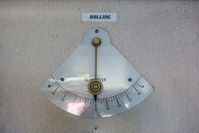
Angle meters are devices used to measure the angle of inclination. There are two types: the pendulum type, which uses a pendulum to estimate position, and the float type, which measures the amount of change in the electrostatic capacity of a float inside a container filled with fluid and gas. Angle meters are not suitable for use in environments subject to frequent vibration, as many products do not support changes in acceleration. When mounted on automobiles or other vehicles that experience acceleration, a gyro sensor should be used to ensure levelness.

Uses of Angle Meters

Angle meters are used in buildings, large facilities, and construction sites where work at heights is required. By measuring the level of the ground, they are used in determining the dimensions of building foundations and ensuring the level when installing the foundations of cranes and other vehicles that work at heights to prevent them from tipping over. When selecting an angle meter, it is necessary to consider the method of measuring inclination, accuracy, given time for measurement, operating environment such as temperature, and connectivity with other equipment.

Principle of Angle Meter

The measurement principle of angle meters is explained separately for the pendulum type and the float type. Angle meters consist of components that measure the horizontal, as well as connection terminals for outputting the measured value, a display unit, and a control panel.

1. Pendulum Type

The pendulum type consists of a pendulum with a magnet attached, a magnetic sensor to detect changes in magnetic force, and oil to suppress minute vibrations. During measurement, the pendulum is swinging toward the center of the earth due to gravity, and the value of the magnetic force, which changes according to the distance between the center of the oscillation and the position of the magnetic sensor, measures the degree of inclination of the angle meter’s installation site.

2. Float Type

The float type consists of a circular container with gas and liquid sealed inside it in the same volume, with two plates that serve as electrodes. During measurement, the liquid surface is inclined according to the inclination angle, and the inclination causes the capacitance of the plates to change, and the inclination angle is measured by measuring the amount of change. Care should be taken when measuring at very high temperatures, as the liquid may vaporize and accurate measurements may not be possible.

カテゴリー
category_usa

Phase Contrast Microscopes

What Is a Phase Contrast Microscope?

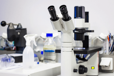
Phase Contrast MicroscopesA phase contrast microscope is a type of optical microscope that converts the phase difference of light into contrast for observation.
With an ordinary optical microscope, differences in the reflection and absorption spectra of light from different parts of a sample are observed as differences in brightness or color (contrast). However, when observing nearly colorless materials such as living cells, microorganisms, and bacteria, these contrasts are almost nonexistent, and information such as shape cannot be obtained.

Even if a material is colorless and transparent, if its refractive index differs from that of its surroundings, the diffraction of light will occur at the boundary. Phase contrast microscopes use the phase difference between the diffracted light and the light traveling straight through the material to create a contrast between light and dark, making it possible to observe colorless transparent materials.

Uses of Phase Contrast Microscopes

Phase contrast microscopes are widely used in biology and medicine for observation of cultured cells and clinical examination. Periodontal bacteriological examination in dental clinics is a familiar application for the public. It helps to motivate patients to take better care of their oral health by letting them know how their own oral bacteria are doing.

Phase contrast microscopes allow observation of live cells without the need to stain the specimen. When observing colorless cells with a conventional optical microscope, the sample is stained for observation, but this method has the disadvantage that the staining is time-consuming and kills living cells.

In addition, phase contrast microscopes are also effective in analyzing asbestos, a toxic substance. One method is the dispersion staining method, in which crystals in the immersion solution with a specific refractive index are irradiated with polarized light under a phase contrast microscope, and the color produced is used to determine whether the sample is asbestos or not.

Principle of Phase Contrast Microscopes

Phase-Contrast-Microscopes_位相差顕微鏡-1.

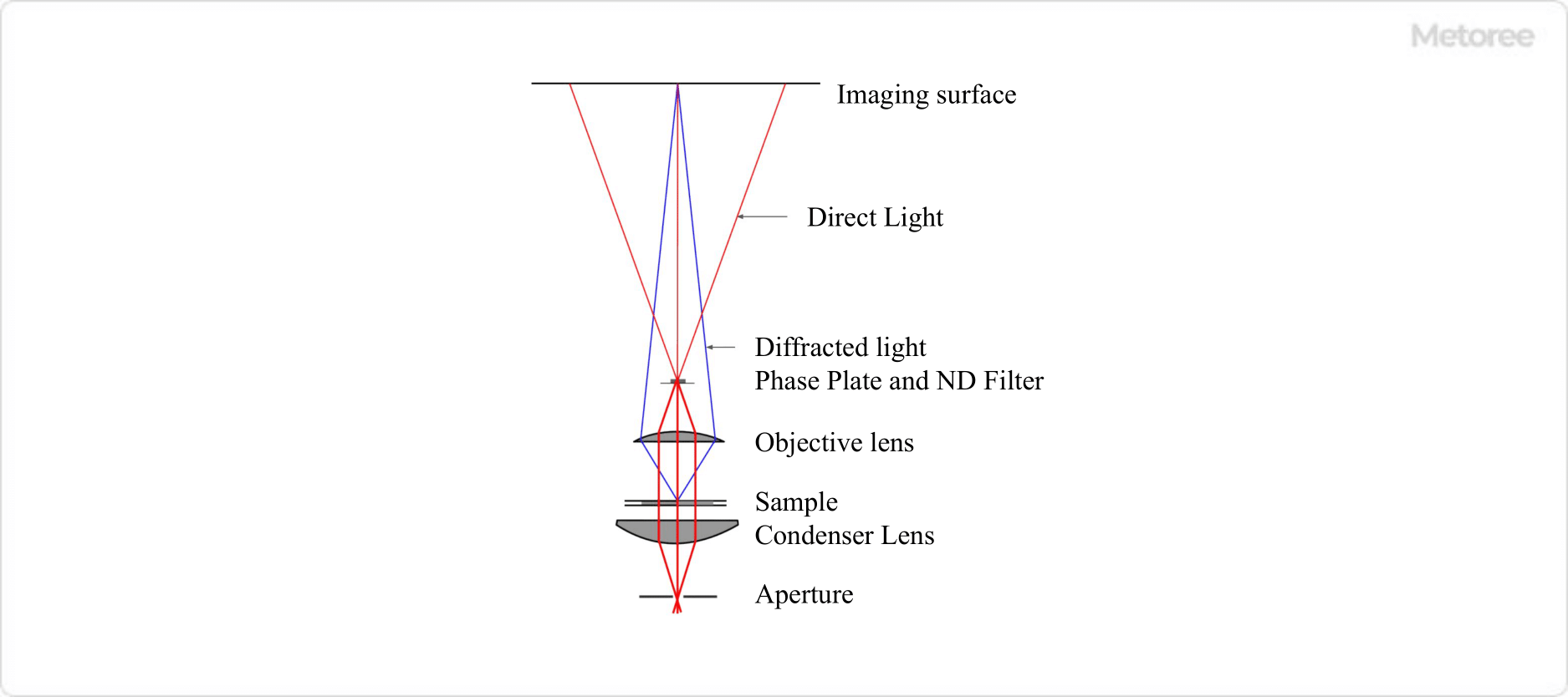
Figure 1. Optical system of a phase contrast microscope

In a phase contrast microscope, a phase plate is inserted only at the position where the direct light passes between the objective lens and the image plane to advance or retard the phase of the direct light by 1/4λ. At the same time, a ring-shaped ND filter is inserted to reduce the intensity of the direct light, but does not change the phase or brightness of the diffracted light.

By these operations, the phase difference between the direct light and diffracted light becomes 1/2λ or 0, and the light and dark contrasts are created by interference.

Phase-Contrast-Microscopes_位相差顕微鏡-2

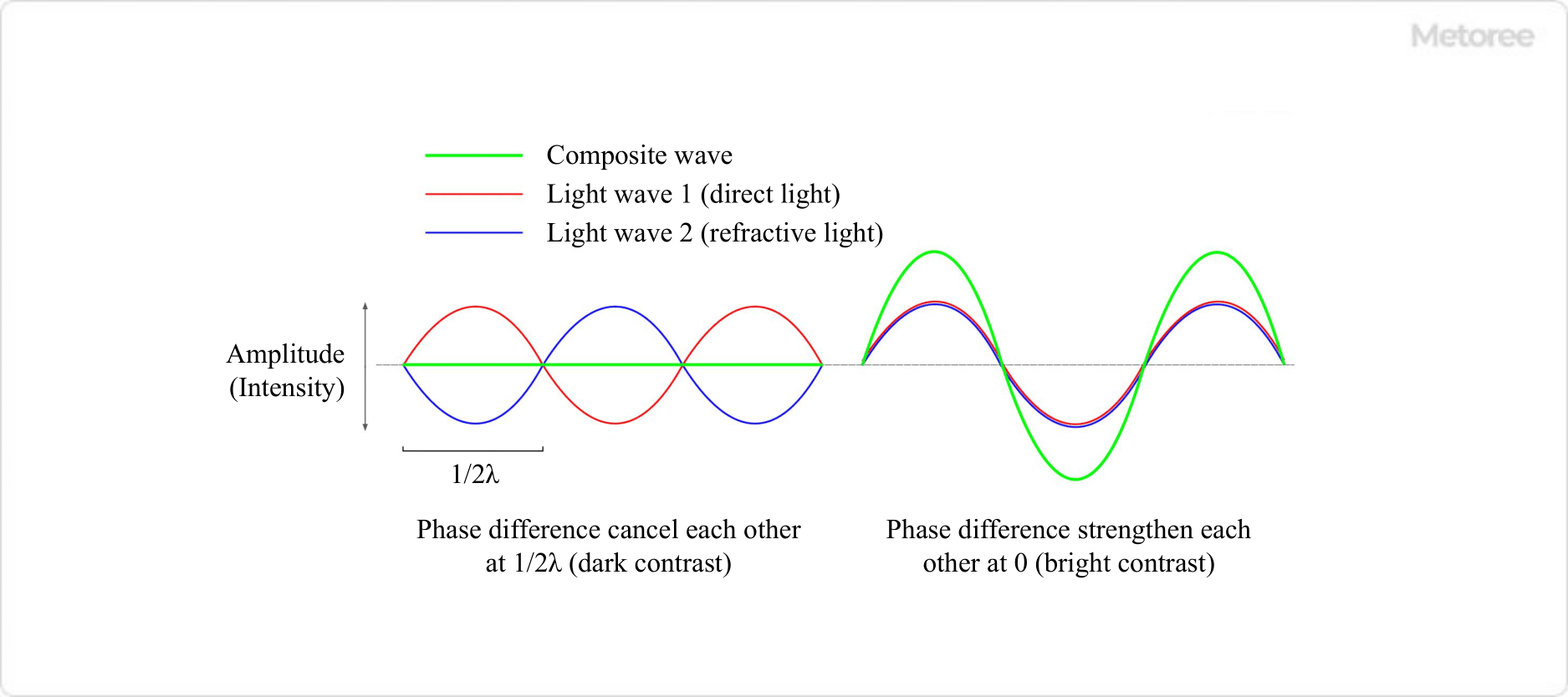
Figure 2. Interference between amplitude-matched direct light and diffracted light

In other words, at the site of a sudden change in refractive index where diffracted light is generated, when the phase difference is 1/2λ, direct light and diffracted light interfere with each other in a weakening manner, resulting in a dark appearance. This is the dark contrast. On the other hand, when the phase difference is 0, direct light and diffracted light interfere with each other in such a way that they strengthen each other, making the site of the abrupt change in refractive index appear bright. This is the bright contrast.

Phase-Contrast-Microscopes_位相差顕微鏡-3

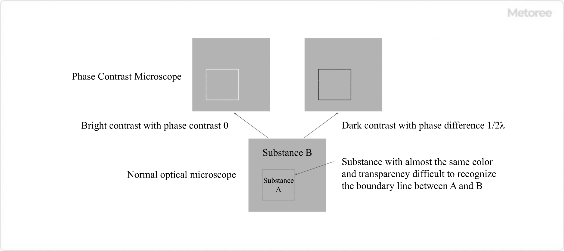
Figure 3. Bright contrast and dark contrast

Other Information on Phase Contrast Microscopes

1. Problems With Optical Microscopes

In ordinary optical microscopy, a substance can be identified by differences in either the intensity (amplitude) or the color (wavelength) or both of the light transmitted through the substance under observation. Therefore, for example, it is not easy to recognize the difference or boundary between a colorless transparent substance A and a colorless transparent substance B that is in contact with another colorless transparent substance A, even if they are observed with an ordinary optical microscope.

This is because there is no difference in the intensity and color of the transmitted light and no contrast between A and B. However, if the refractive indices of substances A and B are different, at the boundary between them, light is divided into direct light that travels straight through the sample and diffracted light whose path is altered. Since diffracted light is generated at the point where the refractive index changes abruptly, it contains information about the boundary shape and internal structure of each material in the sample.

It is important to note that diffracted light is delayed by a quarter of a wavelength (λ) (1/4λ) relative to the direct light traveling straight through the sample. Such a delay of a fraction of a wavelength is called a phase difference. Even if diffracted light is generated, the phase difference is minute because it is very weak compared to direct light.

Therefore, the image formed by adding the direct light and diffracted light together has a wave shape similar to that of the direct light, and no contrast between bright and dark is produced with an ordinary optical microscope.

2. Difference Between Phase Contrast Microscopes and Differential Interference Microscopes

In addition to phase contrast microscope, differential interference microscope is another type of microscope that uses light interference to obtain contrast. In differential interference microscopy, the light incident on a sample is separated into two polarizations with slightly different paths, and the two lights interfere with each other after passing through the object of observation to obtain contrast.

It is similar to the phase contrast microscope in that it can observe colorless and transparent materials, which is impossible with the phase contrast microscope. However, phase contrast microscope provides contrast in areas where the refractive index of the sample changes abruptly, whereas differential interference microscope provides contrast in areas where there is a gradient in the thickness or refractive index of the sample.